

Magtrol 5210-2 User Manual
Model 5210-2 Power Supply
1.0 INTRODUCTION
The Model 5210-2 is a current-regulated power supply and display that is designed for use with
Magtrol’s Dial Weight Dynamometers. With regulated current, torque drift caused by temperature
changes within the brake coil is eliminated.
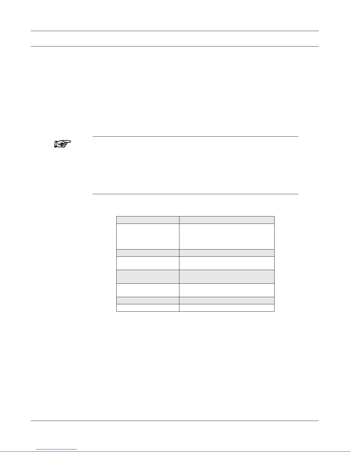
The 5210 is a solid-state control that provides smooth application of current from zero to maximum.
Braking power can be controlled manually from either the 10-turn potentiometer and adjustment
knob on the front panel, or externally from the 0–5 V DC input when remote operation is desired.
An LCD readout conveniently displays the applied braking current.
Note: Magtrol offers three different models of the 5210 Power Supply,
1.1 SpecificationS
each with a different maximum voltage output. The 5210-1 is 90
volts, 5210-2 is 24 volts, and the 5210-3 is 12 volts. All Magtrol
Dial Weight Dynamometers are designed with a 24 volt coil.
Therefore, the 5210-2 is the only power supply that should be used
with a dial weight dynamometer. The 5210-1 and 5210-3 are for
use with Magtrol brakes and clutches only.
Brake Voltage
CURRENT RANGES:
Low Scale
Medium Scale
High Scale
Current Regulation
Braking Control
Brake Fuse (5 × 20 mm)
Line Fuse (5 × 20 mm)
Power Requirements
Voltage Requirements
0 to 24 V DC
0 to 200 mA
0 to 500 mA
0 to 1000 mA
± 1% Full Scale
10-turn potentiometer (internal) or
0–5 V DC input (external)
UL/CSA 1.25 A 250 V SB
IEC 1.00 A 250 V T
120 V: UL/CSA 1.0 A 250 V SB
240 V: IEC 0.4 A 250 V T
100 VA
120/240 V AC 50/60 Hz
1
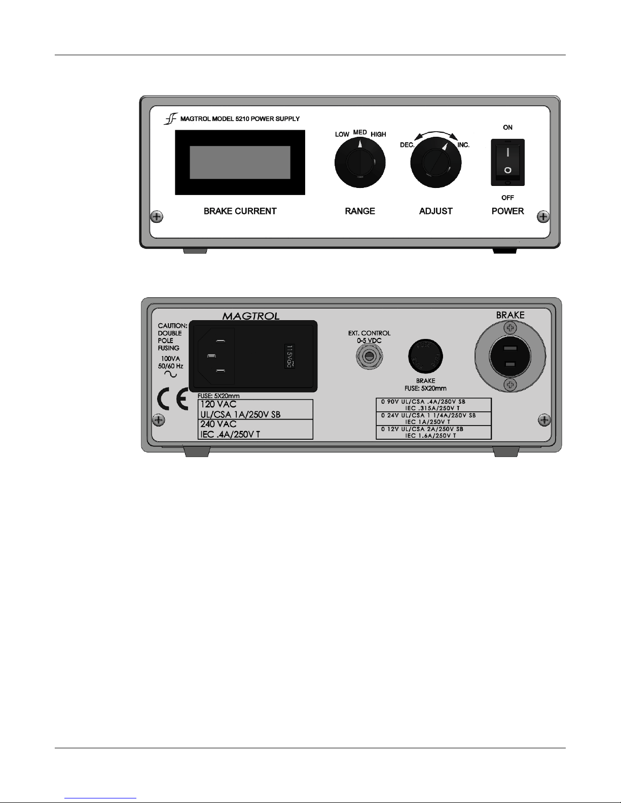
1.2 front and rear panel
Magtrol Model 5210-2 Power SupplyUser’s Manual
1.3 circuit deScription
Functionally, the circuit is a closed loop, current feedback amplifier regulating the output current at
the value set by the front panel controls.
DC current from the internal 35 volt power supply passes through the dynamometer coil connected
at the BRAKE connector J6, through the insulated gate field effect transistor Q1 (HEXFET), and
through a current sense resistor R13, R14 or R15 (selected by the RANGE control). The voltage
drop across the current sense resistor is amplified by Operational Amplifier U1b and applied to the
non-inverting differential input of Operational Amplifier U1a. Amplifier U1a amplifies the difference
between the conditioned current signal from the sense resistor and the voltage from the front panel
current ADJUST potentiometer, R6. This amplified error voltage is applied to the gate of transistor
Q1 to control its channel resistance and thereby regulates the output current at the value set by the
ADJUST control.
2
 Loading...