

Page 1
tDynamo
Three-way Secure Card Reader Authenticator
Installation and Operation Manual
August 2018
Document Number:
D998200257-20
REGISTERED TO ISO 9001:2015
MagTek I 1710 Apollo Court I Seal Beach, CA 90740 I Phone: (562) 546-6400 I Technical Support: (888) 624-8350
www.magtek.com
Page 2

Copyright © 2006 - 2018 MagTek, Inc.
Printed in the United States of America
Information in this publication is subject to change without notice and may contain technical inaccuracies
or graphical discrepancies. Changes or improvements made to this product will be updated in the next
publication release. No part of this document may be reproduced or transmitted in any form or by any
means, electronic or mechanical, for any purpose, without the express written permission of MagTek, Inc.
MagTek® is a registered trademark of MagTek, Inc.
MagnePrint® is a registered trademark of MagTek, Inc.
Magensa™ is a trademark of MagTek, Inc.
MagneSafe™ is a trademark of MagTek, Inc.
AAMVA™ is a trademark of AAMVA.
American Express® and EXPRESSPAY FROM AMERICAN EXPRESS® are registered trademarks of
American Express Marketing & Development Corp.
D-PAYMENT APPLICATION SPECIFICATION® is a registered trademark to Discover Financial
Services CORPORATION
MasterCard® is a registered trademark and PayPass™ and Tap & Go™ are trademarks of MasterCard
International Incorporated.
Visa® and Visa payWave® are registered trademarks of Visa International Service Association.
ANSI®, the ANSI logo, and numerous other identifiers containing "ANSI" are registered trademarks,
service marks, and accreditation marks of the American National Standards Institute (ANSI).
EMV® is a registered trademark in the U.S. and other countries and an unregistered trademark elsewhere.
The EMV trademark is owned by EMVCo, LLC. The Contactless Indicator mark, consisting of four
graduating arcs, is a trademark owned by and used with permission of EMVCo, LLC.
ISO® is a registered trademark of the International Organization for Standardization.
PCI Security Standards Council® is a registered trademark of the PCI Security Standards Council, LLC.
UL™ and the UL logo are trademarks of UL LLC.
The Bluetooth® word mark and logos are registered trademarks owned by Bluetooth SIG, Inc. and any
use of such marks by MagTek is under license.
Google Play™ store and Android™ platform are trademarks of Google Inc.
Apple Pay®, OS X®, iPod touch®, iPhone®, iPod®, and Mac® are registered trademarks of Apple Inc.,
registered in the U.S. and other countries. App StoreSM is a service mark of Apple Inc., registered in the
U.S. and other countries. iPad™ and iPad mini™ are trademarks of Apple, Inc. IOS is a trademark or
registered trademark of Cisco in the U.S. and other countries and is used by Apple Inc. under license.
Microsoft® and Windows® are registered trademarks of Microsoft Corporation.
Microsoft®, Windows® and .NET® are registered trademarks of Microsoft Corporation.
All other trademarks, system names, product names, and trade names are the property of their respective
owners.
tDynamo| Three-way Secure Card Reader Authenticator | Installation and Operation Manual
Page 2 of 39 (D998200257-20)
Page 3

Table 0-1 - Revisions
Rev Number
Date
Notes
10
May 18, 2018
Initial Release
20
Aug 17, 2018
Add supporting information about optional docking stand;
Retrofit new Sleep Mode throughout; Update 3.2 About the
Status LEDs; Remove support for Windows 10 Bluetooth LE
connections; Misc. clarifications and corrections
tDynamo| Three-way Secure Card Reader Authenticator | Installation and Operation Manual
Page 3 of 39 (D998200257-20)
Page 4

LIMITED WARRANTY
MagTek warrants that the products sold pursuant to this Agreement will perform in accordance with
MagTek’s published specifications. This warranty shall be provided only for a period of one year from
the date of the shipment of the product from MagTek (the “Warranty Period”). This warranty shall apply
only to the “Buyer” (the original purchaser, unless that entity resells the product as authorized by
MagTek, in which event this warranty shall apply only to the first repurchaser).
During the Warranty Period, should this product fail to conform to MagTek’s specifications, MagTek
will, at its option, repair or replace this product at no additional charge except as set forth below. Repair
parts and replacement products will be furnished on an exchange basis and will be either reconditioned or
new. All replaced parts and products become the property of MagTek. This limited warranty does not
include service to repair damage to the product resulting from accident, disaster, unreasonable use,
misuse, abuse, negligence, or modification of the product not authorized by MagTek. MagTek reserves
the right to examine the alleged defective goods to determine whether the warranty is applicable.
Without limiting the generality of the foregoing, MagTek specifically disclaims any liability or warranty
for goods resold in other than MagTek’s original packages, and for goods modified, altered, or treated
without authorization by MagTek.
Service may be obtained by delivering the product during the warranty period to MagTek (1710 Apollo
Court, Seal Beach, CA 90740). If this product is delivered by mail or by an equivalent shipping carrier,
the customer agrees to insure the product or assume the risk of loss or damage in transit, to prepay
shipping charges to the warranty service location, and to use the original shipping container or equivalent.
MagTek will return the product, prepaid, via a three (3) day shipping service. A Return Material
Authorization (“RMA”) number must accompany all returns. Buyers may obtain an RMA number by
contacting MagTek Support Services at (888) 624-8350.
EACH BUYER UNDERSTANDS THAT THIS MAGTEK PRODUCT IS
OFFERED AS-IS. MAGTEK MAKES NO OTHER WARRANTY, EXPRESS OR
IMPLIED, AND MAGTEK DISCLAIMS ANY WARRANTY OF ANY OTHER
KIND, INCLUDING ANY WARRANTY OF MERCHANTABILITY OR FITNESS
FOR A PARTICULAR PURPOSE.
IF THIS PRODUCT DOES NOT CONFORM TO MAGTEK’S
SPECIFICATIONS, THE SOLE REMEDY SHALL BE REPAIR OR
REPLACEMENT AS PROVIDED ABOVE. MAGTEK’S LIABILITY, IF ANY,
SHALL IN NO EVENT EXCEED THE TOTAL AMOUNT PAID TO MAGTEK
UNDER THIS AGREEMENT. IN NO EVENT WILL MAGTEK BE LIABLE TO
THE BUYER FOR ANY DAMAGES, INCLUDING ANY LOST PROFITS, LOST
SAVINGS, OR OTHER INCIDENTAL OR CONSEQUENTIAL DAMAGES
ARISING OUT OF THE USE OF, OR INABILITY TO USE, SUCH PRODUCT,
EVEN IF MAGTEK HAS BEEN ADVISED OF THE POSSIBILITY OF SUCH
DAMAGES, OR FOR ANY CLAIM BY ANY OTHER PARTY.
tDynamo| Three-way Secure Card Reader Authenticator | Installation and Operation Manual
Page 4 of 39 (D998200257-20)
Page 5

LIMITATION ON LIABILITY
EXCEPT AS PROVIDED IN THE SECTIONS RELATING TO MAGTEK’S LIMITED WARRANTY,
MAGTEK’S LIABILITY UNDER THIS AGREEMENT IS LIMITED TO THE CONTRACT PRICE OF
THIS PRODUCT.
MAGTEK MAKES NO OTHER WARRANTIES WITH RESPECT TO THE PRODUCT, EXPRESSED
OR IMPLIED, EXCEPT AS MAY BE STATED IN THIS AGREEMENT, AND MAGTEK
DISCLAIMS ANY IMPLIED WARRANTY, INCLUDING WITHOUT LIMITATION ANY IMPLIED
WARRANTY OF MERCHANTABILITY OR FITNESS FOR A PARTICULAR PURPOSE.
MAGTEK SHALL NOT BE LIABLE FOR CONTINGENT, INCIDENTAL, OR CONSEQUENTIAL
DAMAGES TO PERSONS OR PROPERTY. MAGTEK FURTHER LIMITS ITS LIABILITY OF ANY
KIND WITH RESPECT TO THE PRODUCT, INCLUDING NEGLIGENCE ON ITS PART, TO THE
CONTRACT PRICE FOR THE GOODS.
MAGTEK’S SOLE LIABILITY AND BUYER’S EXCLUSIVE REMEDIES ARE STATED IN THIS
SECTION AND IN THE SECTION RELATING TO MAGTEK’S LIMITED WARRANTY.
tDynamo| Three-way Secure Card Reader Authenticator | Installation and Operation Manual
Page 5 of 39 (D998200257-20)
Page 6

FCC INFORMATION
This device complies with Part 15 of the FCC Rules. Operation is subject to the following two
conditions: (1) This device may not cause harmful interference, and (2) This device must accept any
interference received, including interference that may cause undesired operation.
Note: This equipment has been tested and found to comply with the limits for a Class B digital device,
pursuant to part 15 of the FCC Rules. These limits are designed to provide reasonable protection against
harmful interference in a residential installation. This equipment generates, uses and can radiate radio
frequency energy and, if not installed and used in accordance with the instructions, may cause harmful
interference to radio communications. However, there is no guarantee that interference will not occur in a
particular installation. If this equipment does cause harmful interference to radio or television reception,
which can be determined by turning the equipment off and on, the user is encouraged to try to correct the
interference by one or more of the following measures:
Reorient or relocate the receiving antenna.
Increase the separation between the equipment and receiver.
Connect the equipment into an outlet on a circuit different from that to which the receiver is
connected.
Consult the dealer or an experienced radio/TV technician for help.
Caution: Changes or modifications not expressly approved by MagTek could void the
user’s authority to operate this equipment.
CE STANDARDS
Testing for compliance with CE requirements was performed by an independent laboratory. The unit
under test was found compliant with standards established for Class B devices.
UL/CSA
This product is recognized per UL 60950-1, 2nd Edition, 2011-12-19 (Information Technology
Equipment - Safety - Part 1: General Requirements), CSA C22.2 No. 60950-1-07, 2nd Edition,
2011-12 (Information Technology Equipment - Safety - Part 1: General Requirements).
ROHS STATEMENT
When ordered as RoHS compliant, this product meets the Electrical and Electronic Equipment (EEE)
Reduction of Hazardous Substances (RoHS) European Directive 2002/95/EC. The marking is clearly
recognizable, either as written words like “Pb-free,” “lead-free,” or as another clear symbol ( ).
tDynamo| Three-way Secure Card Reader Authenticator | Installation and Operation Manual
Page 6 of 39 (D998200257-20)
Page 7

0 - Table of Contents
Table of Contents
Limited Warranty .............................................................................................................................................. 4
FCC Information ................................................................................................................................................ 6
CE STANDARDS ................................................................................................................................................. 6
UL/CSA ............................................................................................................................................................... 6
RoHS STATEMENT ............................................................................................................................................. 6
Table of Contents .............................................................................................................................................. 7
1 Introduction ............................................................................................................................................... 9
1.1 About tDynamo ................................................................................................................................. 9
1.2 Fixed or Mobile ................................................................................................................................. 9
1.3 Accept Multiple Payment Methods ............................................................................................... 9
1.4 Designed for Business ..................................................................................................................... 9
1.5 Security in Mind .............................................................................................................................. 10
1.6 Simplified Integration .................................................................................................................... 10
1.7 MagneSafe Security Architecture ................................................................................................ 10
1.8 About tDynamo Components ....................................................................................................... 11
1.9 About Terminology ......................................................................................................................... 12
1.10 About Solution Planning ........................................................................................................... 13
2 Installation ............................................................................................................................................... 14
2.1 About Host Software ...................................................................................................................... 14
2.2 Connecting to a Host...................................................................................................................... 15
2.2.1 About Connecting tDynamo to a Host ................................................................................ 15
2.2.2 How to Connect tDynamo to a Host Computer via USB ................................................... 15
2.2.3 How to Connect tDynamo to an iOS Host via Bluetooth LE ............................................. 16
2.2.4 How to Connect tDynamo to an Android Host via Bluetooth LE ..................................... 19
2.3 Mounting tDynamo ........................................................................................................................ 22
2.3.1 About Mounting ...................................................................................................................... 22
2.3.2 How to Mount the Docking Stand........................................................................................ 23
2.3.3 How to Temporarily Dock tDynamo .................................................................................... 24
2.3.4 How to Permanently Dock tDynamo ................................................................................... 24
3 Operation ................................................................................................................................................. 25
3.1 About Operating Modes ................................................................................................................. 25
3.2 About the Status LEDs ................................................................................................................... 26
3.3 About Sounds .................................................................................................................................. 28
3.4 Power Management....................................................................................................................... 29
3.4.1 About Power ........................................................................................................................... 29
3.4.2 How to Check Battery Level.................................................................................................. 29
3.4.3 How to Charge the Battery ................................................................................................... 30
tDynamo| Three-way Secure Card Reader Authenticator | Installation and Operation Manual
Page 7 of 39 (D998200257-20)
Page 8

0 - Table of Contents
3.4.4 How to Power On / Wake Up from Sleep Mode / Power Off .......................................... 30
3.4.5 How to Force Reset ................................................................................................................ 30
3.5 Card Reading .................................................................................................................................. 31
3.5.1 About Reading Cards ............................................................................................................. 31
3.5.2 How to Swipe Magnetic Stripe Cards .................................................................................. 32
3.5.3 How to Insert Contact Chip Cards ........................................................................................ 33
3.5.4 How to Tap Contactless Cards / Devices ........................................................................... 34
4 Maintenance ............................................................................................................................................ 35
5 Developing Custom Software ............................................................................................................... 36
5.1 USB-Based Custom Software ....................................................................................................... 36
5.2 Bluetooth LE-based Custom Software and Apps ....................................................................... 36
5.3 For More Information ..................................................................................................................... 36
Appendix A Technical Specifications ....................................................................................................... 37
tDynamo| Three-way Secure Card Reader Authenticator | Installation and Operation Manual
Page 8 of 39 (D998200257-20)
Page 9

1 - Introduction
1 Introduction
1.1 About tDynamo
Point-of-service and point-of-sale needs to be fast, reliable and secure. tDynamo delivers on all three and
meets the growing demand from your customers to use the latest in technology in the easiest-to-use form
factor. The tDynamo reader is a simple way to take a wide variety of payment methods, in a small,
versatile device. tDynamo is a three way card reader (magnetic stripe, chip card, contactless).
tDynamo product features include:
EMV L1 and L2 Contact
EMV Contactless (most mobile payment applications)
Rechargeable battery with 500 cycle life
Red/Green/Amber General Status LED
Green Contactless Transaction LEDs
Built-in lanyard mount point and locking mount point
Open standards-based encryption 3DES (TDEA)
DUKPT Key Management
MagnePrint® Card Authentication
Unique non-changeable device serial number
Immediate card data tokenization
Device/host authentication
Time bound session IDs
Designed for handheld, fixed with optional stand, or quick-swap solutions
No cable to interfere with handheld reader grip
Convenient battery charging via industry standard USB-C connector or docking stand contacts
Allows over 200 card swipes or insertions over 8 hours between charges
1.2 Fixed or Mobile
tDynamo allows you to easily go between a fixed platform and a mobile platform, giving you the
flexibility your application and environment may need. The optional docking stand can be mounted to a
countertop with one screw and nut, making installation simple. tDynamo uses very little real estate, while
providing an easy to use payment device that accepts multiple payment methods.
1.3 Accept Multiple Payment Methods
tDynamo is a versatile reader in a simple and easy to understand design. With all of the payment methods
in the market today, tDynamo delivers magnetic stripe, chip card, and contactless in a small form factor.
Now you can accept classic plastic to mobile wallets and just about everything in between.
1.4 Designed for Business
tDynamo delivers a sleek design engineered to work in today’s changing retail environments. Whether
you are offering concierge service, pay-at-the-table, line-busting solutions, or other retail solutions,
tDynamo lets you set the trends instead of trying to keep up. Although in a small form factor, it delivers a
long smooth swipe path with excellent performance and one of the highest first swipe read rates in the
industry. The chip card insertion path is smooth and easy to access, and the contactless pad is sleek and
simple.
tDynamo| Three-way Secure Card Reader Authenticator | Installation and Operation Manual
Page 9 of 39 (D998200257-20)
Page 10

1 - Introduction
1.5 Security in Mind
Data is protected and encrypted the moment the card is swiped, so clear data never enters your system.
Open, 3DES end-to-end encryption and industry-standard DUKPT key management allow for greater
platform flexibility. Ask a representative for more information about MagTek and Magensa’s data
protection and transaction services.
1.6 Simplified Integration
MagTek understands the value of easy-to-use and well documented Software Development Kits (SDKs),
technical documentation, APIs, and sample code. MagTek SDKs have no royalties or maintenance fees
and are free to redistribute with your application. Use MagTek’s MagneFlex browser or middleware
application for even easier development.
1.7 MagneSafe Security Architecture
The MagneSafe Security Architecture provides the maximum security at the minimum cost, both in total
dollars and implementation effort. MagneSafe delivers a layered approach to transaction security, and
combines encryption, tokenization, authentication and dynamic data to protect card data at the moment
the card is swiped.
tDynamo| Three-way Secure Card Reader Authenticator | Installation and Operation Manual
Page 10 of 39 (D998200257-20)
Page 11
1 - Introduction
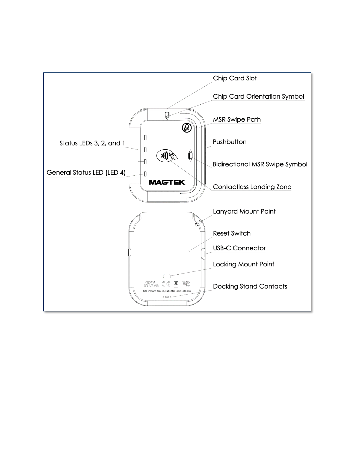
1.8 About tDynamo Components
The major components of tDynamo are shown in Figure 1-1 below. The major components of the
optional tDynamo docking stand are shown in Figure 1-2 below.
Figure 1-1 - tDynamo Major Components
tDynamo| Three-way Secure Card Reader Authenticator | Installation and Operation Manual
Page 11 of 39 (D998200257-20)
Page 12
1 - Introduction
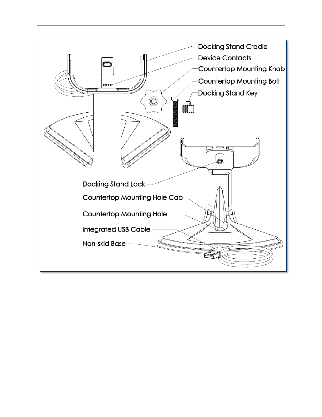
Figure 1-2 - tDynamo Stand Major Components
1.9 About Terminology
In this document, tDynamo is referred to as the device. It is designed to be connected to a host, which is
a piece of general-purpose electronic equipment which can send commands and data to, and receive data
from, the device. Host types include PC computers/laptops, tablets, and smartphones. Generally, the host
must have software installed that communicates with the device and is capable of processing
transactions. During a transaction, the host and its software interact with the operator, such as a cashier
or bank teller, while the device interacts with the cardholder.
tDynamo| Three-way Secure Card Reader Authenticator | Installation and Operation Manual
Page 12 of 39 (D998200257-20)
Page 13

1 - Introduction
1.10 About Solution Planning
A smooth deployment of a tDynamo solution requires some up-front planning and decision-making:
Determine what type of host tDynamo will connect to. This can be a computer with a USB port or a
host with Bluetooth 4.0 hardware that supports Bluetooth LE. When planning, include any additional
support or devices required by the host, such as physical locations, mounting, and power connections.
Determine what software will be installed on the host and how it will be configured. Software can
include operating system, transaction processing software, security software, and so on. Include any
additional support required by the software, such as network connections.
Select which connection type the solution will use. tDynamo can connect physically via its USB-C
connector or to the optional docking stand, or via Bluetooth LE. It connects logically as a vendordefined HID device or GATT device, respectively. Be sure to specify the desired connection settings
when ordering the device. If necessary, they can be reconfigured afterward.
Determine how tDynamo should be configured, and specify that when you order devices. For
example, although tDynamo comes with a factory default Bluetooth LE passkey, it is a good idea to
choose and set non-default passkeys early in the planning process, or request non-default passkeys
when ordering devices.
Determine what the solution will use as a primary power source. tDynamo can be powered by a
USB host through the USB-C connector or the optional docking stand, or can be powered by its
internal rechargeable battery.
Determine the battery recharge schedule(s). For example, in high-traffic mission-critical solutions,
it may be wise to keep spare devices configured and charged for fast swap-out.
Determine how tDynamo will be physically presented to the cardholder. This includes whether the
device will be handheld, permanently mounted to a countertop in the optional docking stand, or
handheld and placed in the docking stand for easy charging. When planning placement, be sure to
consider the connection type and power source. For example, if the primary data connection is USB,
the mounting location should be within reasonable USB cabling distance from the host.
Determine how tDynamo will be branded. In large quantities, MagTek can accommodate custom
branding colors and trade dress. Contact a representative for details.
tDynamo| Three-way Secure Card Reader Authenticator | Installation and Operation Manual
Page 13 of 39 (D998200257-20)
Page 14

2 - Installation
2 Installation
Installing tDynamo is a straightforward process: The acquirer configures the encryption keys and EMV
terminal / payment brand settings before deployment. End users need only set up a host with appropriate
software, configure the software, and connect the device to the host. This section provides general
information about setting up solutions that incorporate tDynamo, including host software, connecting the
device, and mounting the device.
2.1 About Host Software
In any solution, tDynamo is connected to a host, which must have software installed that knows how to
communicate with the device, and which is capable of performing actions intended to be carried out when
a cardholder swipes, inserts, or taps a payment method. To set up the host software to work with
tDynamo, follow the installation and configuration instructions provided by the vendor of the host or the
host software. For details about developing host software, see section 5 Developing Custom Software.
Some connection types may also require installation of device drivers on the host. To set up any
necessary drivers, see the connection-specific “How To” sections in section 2.2 Connecting to a Host.
tDynamo| Three-way Secure Card Reader Authenticator | Installation and Operation Manual
Page 14 of 39 (D998200257-20)
Page 15

2 - Installation
2.2 Connecting to a Host
2.2.1 About Connecting tDynamo to a Host
tDynamo can connect to a host via a variety of connections. Solution designs generally choose one
connection type and do not switch between them, though the device does provide features that allow the
host to actively manage its active connections and connection behaviors (see section 5 Developing
Custom Software). The following sections provide steps for connecting tDynamo to a host via each
connection type.
2.2.2 How to Connect tDynamo to a Host Computer via USB
tDynamo can connect to a USB host or charger either via its USB-C Connector or the optional docking
stand. If the device is using USB as a power source but not as a host connection, also see the sections
below about connecting the device using Bluetooth LE. If the device is connected to two USB
connections at the same time, the docking stand connection takes precedence as a power source, and the
device’s configuration determines which connection it uses to send card swipe data.
To connect tDynamo to a host computer using the optional docking stand, see section 2.3 Mounting
tDynamo. To connect tDynamo to a host computer using the USB-C Connector, follow these steps:
1) Make sure tDynamo is configured to use the USB-C connector as its primary connection. If it is
configured to use another connection, use that connection first to change the configuration.
2) Connect the small end of the USB cable to tDynamo’s USB-C connector as shown in Figure 2-1.
3) Connect the large end of the USB cable to the host computer’s USB port.
4) Power on the host computer.
5) On the host, install and configure the host software you intend to use with tDynamo (if you do not yet
have that software, you can use MTNETDemo.exe included in SOFTWARE, SDK, DYNAMAG /
DYNAMAX / EDYNAMO / UDYNAMO / ADYNAMO / MDYNAMO / TDYNAMO /
DYNAWAVE (WINDOWS .NET), available from MagTek.com, to perform simple tests):
a) Make sure the host software is configured to look for the device on the proper connection type.
b) Make sure the host software knows which device(s) it should interface with.
c) Make sure the host software is configured to properly interpret incoming data from the device.
For direct USB connections, tDynamo transmits data as a vendor-defined HID device.
6) Use the host software to test swiping, inserting, and tapping a card (see section 3.5 Card Reading).
Figure 2-1 - Connecting tDynamo to a Host Computer via USB
tDynamo| Three-way Secure Card Reader Authenticator | Installation and Operation Manual
Page 15 of 39 (D998200257-20)
Page 16

2 - Installation
2.2.3 How to Connect tDynamo to an iOS Host via Bluetooth LE
To connect tDynamo to an iOS host that supports Bluetooth LE, follow these steps:
1) Make sure tDynamo is configured to use Bluetooth LE as its primary connection. If it is configured
to use another connection, use that connection first to change the configuration.
2) If any other Bluetooth LE host has an active data connection to the device, close the connection.
3) On the host, install and configure the host software you intend to use with tDynamo. If you do not
yet have that software, you can download a test tool from the App Store called MagTek Test,
published by MagTek, Inc..
4) Make sure tDynamo is powered on, is not in sleep mode, and that its battery is adequately charged
(see section 3.4.1 About Power for instructions).
5) Press the pushbutton for 2 seconds until the General Status LED flashes three times, then release the
pushbutton to enter Pairing Mode. The General Status LED flashes blue up to 2 minutes or until a
host pairs or connects.
6) On the iOS host, launch the Settings app, select Bluetooth, and make sure the host’s Bluetooth
radio is turned On.
7) Use the host application or the MagTek Test app (not the device’s Settings app) to pair with and
connect to the device. If you are using the MagTek Test app, the steps are as follows. Other host
software may be similar:
a) Launch the host software app.
b) Select BLE EMV as the device type.
c) Press the Connect button.
tDynamo| Three-way Secure Card Reader Authenticator | Installation and Operation Manual
Page 16 of 39 (D998200257-20)
Page 17

2 - Installation
d) When the app prompts you to select a BLE EMV Type, select tDynamo.
e) Locate the seven-digit serial number on the label on the back of the device.
f) In the list of pairable devices, select tDynamo-xxxxxxx, where xxxxxxx is the device’s serial
number.
8) When the host pops up a Bluetooth Pairing Request message asking for a code, enter the
configured passkey (or the default 000000).
9) The app reports the device is now Connected, and the device indicates it is in Connected mode (see
section 3.2 About the Status LEDs).
10) Use the host software or the MagTek Test app to test swiping, inserting, and tapping a card. For
details about reading each payment type, see section 3.5 Card Reading.
a) Before testing a swipe, use the app to Send command 580101 to the device and receive
response 0000 to enable the magnetic stripe read head. For convenience, the MagTek Test app
provides an MSR On button that sends this command to the device with a single press.
tDynamo| Three-way Secure Card Reader Authenticator | Installation and Operation Manual
Page 17 of 39 (D998200257-20)
Page 18

2 - Installation
b) After swipe testing, Send command 580100 to disable it and conserve power.
11) Remember to change the default passkey. See the tDynamo Programmer’s Manual documentation
for details.
To unpair from the device, follow these steps:
1) On the iOS host, launch the Settings app and select Bluetooth.
2) Press the “i” information icon next to the device’s name in the MY DEVICES list.
3) Select Forget This Device and make sure the device disappears from MY DEVICES.
tDynamo| Three-way Secure Card Reader Authenticator | Installation and Operation Manual
Page 18 of 39 (D998200257-20)
Page 19

2 - Installation
2.2.4 How to Connect tDynamo to an Android Host via Bluetooth LE
To connect tDynamo to an Android host that supports Bluetooth LE:
1) Make sure tDynamo is configured to use Bluetooth LE as its primary connection. If it is configured
to use another connection, use that connection first to change the configuration.
2) If any other Bluetooth LE host has an active data connection to the device, close the connection.
3) On the Android host, install and configure the host software you intend to use with tDynamo. If you
do not yet have that software, you can download a test tool from the Google Play store called
MagTek Test, published by MagTek, Inc..
4) Make sure tDynamo is powered on, is not in sleep mode, and that its battery is adequately charged
(see section 3.4.1 About Power for instructions).
5) Press and hold the pushbutton for 2 seconds until the General Status LED flashes three times, then
release the pushbutton to enter Pairing Mode. The General Status LED flashes blue up to 2 minutes
or until a host pairs or connects.
6) On the Android host, launch the Settings application, and open the Bluetooth settings page or the
Connected Devices > Bluetooth settings page.
7) Make sure the host has Bluetooth turned On.
8) Press the SEARCH FOR DEVICES / Scan / Pair new device button to show an Available
devices list.
9) Locate the seven-digit serial number on the label on the back of the device.
10) In the list of pairable devices, select the device called tDynamo-xxxxxxx, where xxxxxxx is the
device’s serial number.
tDynamo| Three-way Secure Card Reader Authenticator | Installation and Operation Manual
Page 19 of 39 (D998200257-20)
Page 20

2 - Installation
11) When the host asks for a passcode or PIN, enter tDynamo’s configured passkey (or the default
000000), then press the OK button. The device appears in the Paired devices list.
12) Use the host software or the MagTek Test app to connect to the device and to test swiping, inserting,
and tapping a card. For details about reading each payment type, see section 3.5 Card Reading.
a) After connecting to the device, the app reports the device is now Connected, and the device
indicates it is in Connected mode (see section 3.2 About the Status LEDs).
b) Before testing a swipe, use the app to Send command 580101 to the device and receive
response 0000 to enable the magnetic stripe read head.
c) After swipe testing, Send command 580100 to disable it and conserve power.
tDynamo| Three-way Secure Card Reader Authenticator | Installation and Operation Manual
Page 20 of 39 (D998200257-20)
Page 21

2 - Installation
13) Remember to change the default passkey. See the tDynamo Programmer’s Manual documents for
details.
To unpair from the device, follow these steps:
1) Locate the device in the Bluetooth configuration page.
2) Press the settings (gear) icon.
3) Press the Unpair or Forget button and make sure the device disappears from the Paired devices
list.
tDynamo| Three-way Secure Card Reader Authenticator | Installation and Operation Manual
Page 21 of 39 (D998200257-20)
Page 22

2 - Installation
2.3 Mounting tDynamo
2.3.1 About Mounting
tDynamo’s design provides two mount points: A Lanyard Mount Point and a Locking Mount Point
(see section 1.8 About tDynamo Components). The two mount points can be used in various
combinations:
The lanyard mount point can be used to hang the device for convenient hanging storage and/or
handling in handheld sales solutions.
The locking mount point can be used with the optional docking stand (shown in Figure 2-2) mounted
to a countertop for stability in stationary sales solutions.
The locking mount point can also be used with custom brackets to mount to other devices or surfaces.
The docking stand can also be used in unlocked mode, and optionally combined with the lanyard
mount point, for quick grab-and-go and convenient drop-in charging between handheld sessions.
Figure 2-2 - tDynamo Installed On Optional Docking Stand
tDynamo| Three-way Secure Card Reader Authenticator | Installation and Operation Manual
Page 22 of 39 (D998200257-20)
Page 23

2 - Installation
2.3.2 How to Mount the Docking Stand
To mount the docking stand to a countertop, follow these steps (see Figure 2-3):
1) Determine where the docking stand should be placed: Factors to consider include cable length,
cardholder and operator ergonomics, and access for cleaning and repair.
a) If the docking stand will be used for charging in handheld operations, unobstructed removal is
also a consideration.
b) If the device will be permanently docked for cardholder use, placing the stand so it hangs slightly
over the edge of the surface may provide the least obstructed swipe path.
2) Open the protective cap over the mounting hole on the base of the docking stand.
3) Place the docking stand at the desired location and mark the center of the mounting hole on the
countertop, then set the docking stand aside.
4) Drill a ¼” hole all the way through the countertop.
5) Line up the hole in the stand over the hole in the countertop.
6) Thread the included bolt through docking stand’s mounting hole and the countertop hole.
7) Fasten the included knob to the bolt and tighten it.
8) Replace the docking stand’s protective cap.
9) Connect the docking stand’s USB cable to the host.
Figure 2-3 - Optional Docking Stand Assembly
tDynamo| Three-way Secure Card Reader Authenticator | Installation and Operation Manual
Page 23 of 39 (D998200257-20)
Page 24

2 - Installation
Do not leave the round key installed in the docking stand. The key is designed to be
removed to deter unauthorized removal of the device.
2.3.3 How to Temporarily Dock tDynamo
To temporarily dock the device in the docking stand for convenient charging, follow these steps:
1) If the docking stand will be mounted to a countertop, follow the steps in section 2.3.2 How to Mount
the Docking Stand to do that first.
2) Make sure the docking stand is connected to a USB host.
3) Make sure the device’s docking stand contacts are clean and unobstructed.
4) Place the device all the way into the docking stand. The device powers on automatically and begins
charging.
2.3.4 How to Permanently Dock tDynamo
To permanently attach the device to the docking stand, follow these steps:
1) Make sure tDynamo is configured to use the docking contacts as its primary connection. If it is
configured to use another connection, use that connection first to change the configuration.
2) Follow the steps in section 2.3.3 How to Temporarily Dock tDynamo to place the device on the
docking stand.
3) Use the included round key to turn the locking screw on the back of the stand to lock the device in
place.
4) Remove the key and set it aside for future use, such as cleaning or servicing the device. It has a key
ring / string hanger loop integrated into its handle for convenience.
5) Make sure the device is firmly locked into the stand.
tDynamo| Three-way Secure Card Reader Authenticator | Installation and Operation Manual
Page 24 of 39 (D998200257-20)
Page 25

3 - Operation
3 Operation
3.1 About Operating Modes
During operation, tDynamo transitions between six distinct modes, each of which behaves differently:
Reset Mode occurs when the user presses and the recessed reset switch or holds the pushbutton for 5
to 10 seconds. After resetting, the device progresses to Powered Off Mode. If the device is
connected to USB power, it immediately progresses to Discoverable Mode.
Powered Off Mode is the shipping mode of the device. The operator can power off by pressing and
holding the pushbutton, and the device enters this mode automatically if it has been in Sleep Mode for
a configurable timeout period. When powered off, the device consumes practically no power. To
move the device from Powered Off Mode to Discoverable Mode, press the pushbutton briefly or
connect the device to a USB charger or USB host. When the device is connected to a host via USB,
the device immediately progresses to Connected Mode.
Battery Status Mode is a short mode that uses all four Status LEDs to report the current charge level
of the device’s rechargeable battery (see section 3.4.1 About Power). The operator activates this
mode by tapping the pushbutton briefly in Discoverable Mode or Connected Mode. The device
automatically exits to the previous mode after a short period of time.
Discoverable Mode is the device’s normal waiting state. The operator activates this mode when the
device is not connected to USB by briefly pressing the pushbutton once while in Powered Off Mode.
In this mode, the device remains paired with any previously paired Bluetooth LE hosts, but is not
connected to transmit data. Upon entering Discoverable Mode, the device advertises itself over
Bluetooth LE, and any paired Bluetooth LE host may initiate a connection. To move the device from
Discoverable Mode to Pairing Mode, press and hold the pushbutton for about two seconds until the
General Status LED flashes, then release the pushbutton. If the device is not connected to USB
power, it will move from Discoverable Mode to Sleep Mode automatically when its configurable
timeout period has passed. If the device is configured to transmit data over USB and is connected to
a USB host, it immediately progresses from Discoverable Mode to Connected Mode.
Pairing Mode is activated while the device is powered on by pressing the pushbutton for two seconds
and waiting for the General Status LED to flash, then releasing the pushbutton. In this mode, an
unpaired Bluetooth LE host may initiate pairing. Upon entering Pairing Mode, the device advertises
over Bluetooth LE, and continues to be pairable until a Bluetooth LE host pairs with it or until a
2-minute timeout period expires. Upon successful pairing, the device enters Discoverable Mode.
Connected Mode occurs when the device is connected to a USB host, or when a paired Bluetooth LE
host initiates a connection (generally in response to the host software’s graphical user interface). In
this mode, the host and the device can both initiate communication, and it is the Bluetooth LE host’s
responsibility to terminate the connection and return the device to Discoverable Mode to save power
when an active data connection is no longer needed for the current transaction. If the device is not
connected to USB power, it will move from Connected Mode to Sleep Mode automatically when its
configurable Sleep Mode timeout period has passed. If the device is connected to a Bluetooth LE
host, it does not advertise and is not discoverable by other Bluetooth LE hosts. If the device is
connected to a USB host, it continues to advertise and is discoverable by Bluetooth LE hosts.
Sleep Mode is a low-power standby state. The device enters this mode automatically when it is not
connected to USB power and has been unused (no user input, no communication with the host) for a
configurable timeout period. In this mode, the device turns off all Bluetooth LE functions. To move
the device from Sleep Mode to Discoverable Mode, press the pushbutton briefly or connect the device
to a USB charger. To move the device from Sleep Mode to Connected Mode, connect the device to a
USB host. The device moves from Sleep Mode to Powered Off Mode automatically when its
configurable Power Off timeout period has passed.
tDynamo| Three-way Secure Card Reader Authenticator | Installation and Operation Manual
Page 25 of 39 (D998200257-20)
Page 26

3 - Operation
Color
Flashing Pattern
Meaning
Off
Off
The device is powered off, or the battery is
completely drained and needs to be recharged.
Green
Flashing Periodically
The device flashes the General Status LED every 5
seconds when it is powered on and is in Connected
mode, ready for the host to send it a command or
for a cardholder to swipe a magnetic stripe card.
The color indicates the battery charge level:
Green = Recharge if desired
Amber = Recharge soon
Red = Recharge immediately (device can not
process transactions)
Amber
Red
Green
LEDs 4, 3, 2, 1 Light
In Sequence
The device has read a contactless tap, and the
cardholder can safely remove the card or device
from the contactless landing zone.
Green
LEDs 4, 3, 2, 1 Light
Simultaneously
The device has just been powered on and is testing
the four Status LEDs.
Green
LEDs 4, 3, 2, 1 Light
In Combination
An operator has pressed the pushbutton briefly and
the device is reporting battery charge level. See
section 3.4.1 About Power.
Green
Steady On
The General Status LED (LED 4) is lit green when
the host has initiated an EMV transaction that
allows the cardholder to present a contactless card
or contactless device.
Blue
Solid On
The General Status LED (LED 4) is lit blue when
the operator presses the pushbutton, to provide
feedback that the pushbutton is working correctly.
Blue
Three Flashes
The operator has pressed the pushbutton for 2
seconds, and the device will transition to Pairing
Mode if the operator releases the pushbutton.
Blue
Short Flashing
The device is in Pairing Mode, advertising, and
ready for a Bluetooth LE host to initiate pairing.
3.2 About the Status LEDs
tDynamo’s General Status LED (LED 4) and Status LEDs 3, 2, and 1 provide feedback to the operator
and cardholder about the internal state of the device (see section 1.8 About tDynamo Components).
Table 3-1 shows how to interpret the colors and flashing patterns of the General Status LED.
Table 3-1 - tDynamo Status LED Meanings
tDynamo| Three-way Secure Card Reader Authenticator | Installation and Operation Manual
Page 26 of 39 (D998200257-20)
Page 27

3 - Operation
Color
Flashing Pattern
Meaning
Red
Steady On
The device is in Sleep Mode. The General Status
LED is solid red and LED 3 is solid green.
Red
Steady On
An operator is updating the firmware. On
completion, the device resets and all LEDs turn off
briefly.
tDynamo| Three-way Secure Card Reader Authenticator | Installation and Operation Manual
Page 27 of 39 (D998200257-20)
Page 28

3 - Operation
3.3 About Sounds
tDynamo’s beeper provides feedback to operators and cardholders about the internal state of the device:
The device sounds one short beep on startup to test the beeper and indicate the device is powered on.
The device sounds one short beep after it has successfully read a contactless tap, and the cardholder
can safely remove the card or device from the contactless landing zone.
The device sounds two beeps when an operator cancels a pending EMV transaction.
The device sounds two short beeps when an operator successfully powers it off.
tDynamo| Three-way Secure Card Reader Authenticator | Installation and Operation Manual
Page 28 of 39 (D998200257-20)
Page 29

3 - Operation
3.4 Power Management
3.4.1 About Power
tDynamo can be powered by one of two power sources: USB or the built-in rechargeable battery.
When the device is connected to a USB host or charger via the USB-C connector or the optional docking
stand, it receives power through the USB connection. In this case, the device powers on automatically,
recharges the built-in rechargeable battery, and stays powered on.
When the device is not connected to a USB power source, it receives power from its onboard
rechargeable battery. In this case, after a period of inactivity (no host commands and no user interaction),
the device transitions to a low-power Sleep Mode, which it indicates by turning the General Status LED
solid red and LED 3 solid green. When the device is already in Sleep Mode, after a further period of
inactivity, the device powers off completely and turns off all LEDs.
The host can set the device’s Sleep Mode and Power Off timeouts to values that are appropriate for the
specific solution design. For details about developing host software to configure the device, see section 5
Developing Custom Software.
For details about the device’s behavior in its various power modes, see section 3.1 About Operating
Modes. For instructions to check and recharge the battery, power the device on and off, and wake the
device from sleep mode, see the following sections.
3.4.2 How to Check Battery Level
To check the battery charge level, make sure the device is powered on and awake, then briefly tap the
pushbutton. The Status LEDs light to show the battery level as follows:
One LED = Battery level is under 50%
Two LEDs = Battery level is between 50% and 70%
Three LEDs = Battery level is between 70% and 90%
Four LEDs = Battery level is above 90%
Figure 3-1 - Status LEDs Showing Battery Level
tDynamo| Three-way Secure Card Reader Authenticator | Installation and Operation Manual
Page 29 of 39 (D998200257-20)
Page 30

3 - Operation
When the device is in Connected mode (see section 3.1 About Operating Modes), the General Status
LED blinks periodically to indicate the device is ready for the host to send a command or for a cardholder
to swipe a magnetic stripe card. The color of the blink indicates the battery level. See section 3.2 About
the Status LEDs for details.
Custom host software may also query the device and show its current charge level on the host display at
all times for convenience. For details, see section 5 Developing Custom Software.
3.4.3 How to Charge the Battery
tDynamo has an onboard rechargeable battery to supply its own power when it is not powered through its
USB-C connector or docking stand connectors. The battery must be periodically recharged by connecting
it to the optional docking stand, or to a USB port or stand-alone USB charger using a USB-C cable. Both
the docking stand and the USB-C connector require a USB connection that can provide at least 500mA @
5V. A full recharge cycle for a completely drained battery takes approximately 4.5 hours.
To charge the device using a USB-C cable, connect it to a USB charger or to a USB host as shown in
section 2.2.2 How to Connect tDynamo to a Host Computer via USB.
To charge the device in the docking stand, see section 2.3.3 How to Temporarily Dock tDynamo.
3.4.4 How to Power On / Wake Up from Sleep Mode / Power Off
If all LEDs are off, the device is in Powered Off mode. If the General Status LED is solid red and LED 3
is solid green, the device is in Sleep Mode. To power on the device or to wake it from Sleep Mode, tap
the pushbutton. In response, the device lights all of the Status LEDs to perform a quick LED test, then
transitions to either Discoverable Mode or Connected Mode. For details, see section 3.1 About
Operating Modes and section 3.2 About the Status LEDs.
To power off the device, press and hold the pushbutton for 5 to 10 seconds until all LEDs turn off and the
device beeps twice.
3.4.5 How to Force Reset
To force the device to reset, use a small tool such as a paperclip to carefully press the reset switch
recessed inside the small hole on the back of the device (see Figure 1-1).
tDynamo| Three-way Secure Card Reader Authenticator | Installation and Operation Manual
Page 30 of 39 (D998200257-20)
Page 31

3 - Operation
3.5 Card Reading
3.5.1 About Reading Cards
The steps for starting a transaction and reading a card or contactless payment device are different
depending on tDynamo’s configuration and on the design of the host software. Host software developers
should see section 5 Developing Custom Software for implementation references. The solution
developer should provide solution-specific instructions for operators to follow. A transaction generally
follows this essential flow:
1) An advanced operator makes sure tDynamo is configured properly and is connected to the host (see
section 2.2 Connecting to a Host). When the device is connected to the host via USB and powered
by the USB-C connector or docking stand, generally the host always keeps a connection open to the
device. When connected to the host via Bluetooth LE, the device must already be paired with the
host, and the host must be initiate a Bluetooth LE connection to process a transaction, then would
generally disconnect after the transaction is complete to conserve power.
2) The operator makes sure tDynamo is receiving power either from its rechargeable battery or from one
of the USB connections, and is awake and powered on (see section 3.4.4 How to Power On / Wake
Up from Sleep Mode / Power Off and section 3.2 About the Status LEDs).
3) The operator uses the host user interface (for example, a point of sale) to finalize a transaction
amount, then initiates a transaction.
4) The host communicates with the device, and reports to the operator when the device is ready.
5) The operator directs the cardholder in presenting payment.
6) The cardholder interacts with the device to present payment. The following sections provide
additional details about presenting each of the available payment methods.
7) Because the device does not have its own display, the device may send messages to the host
prompting the cardholder to perform certain actions; the host software should process these requests
by displaying the requested messages, and depending on the placement of the host display(s), the
operator may need to relay the messages to the cardholder. For example:
a) If the device can not read the card, it may prompt the cardholder to swipe, insert, or tap again.
b) If the device repeatedly can not read a chip card, it may revert to using the magnetic stripe reader
instead of the chip card slot. This is known as EMV fallback.
8) The device reports the success or failure of the transaction to the host, which should report the results
to the operator.
tDynamo| Three-way Secure Card Reader Authenticator | Installation and Operation Manual
Page 31 of 39 (D998200257-20)
Page 32

3 - Operation
3.5.2 How to Swipe Magnetic Stripe Cards
Cardholders should swipe magnetic stripe cards in the MSR swipe path, indicated by the bidirectional
MSR swipe symbol shown on the device’s face. The magnetic stripe must face toward and into the
device, as shown in Figure 3-2. Cardholders may swipe in either direction along the path.
Figure 3-2 - Swiping a Card Through tDynamo
tDynamo| Three-way Secure Card Reader Authenticator | Installation and Operation Manual
Page 32 of 39 (D998200257-20)
Page 33

3 - Operation
3.5.3 How to Insert Contact Chip Cards
Cardholders should insert chip cards into the chip card slot, indicated by the chip card orientation symbol
shown on the device’s face. See Figure 3-3.
Figure 3-3 - Inserting a Chip Card Into tDynamo
tDynamo| Three-way Secure Card Reader Authenticator | Installation and Operation Manual
Page 33 of 39 (D998200257-20)
Page 34

3 - Operation
3.5.4 How to Tap Contactless Cards / Devices
To tap a contactless card or electronic payment device, cardholders should do the following:
1) If the cardholder is using an electronic payment device, such as a smart phone, make sure the
payment device has NFC turned On and has a payment app configured to process transactions. For
details, see the documentation provided by the smart phone manufacturer and payment app publisher.
2) Wait until the device’s General Status LED lights solid green, indicating it is ready for a tap.
3) Tap the card or electronic payment device on the contactless landing zone, indicated by the EMVCo
Contactless Indicator symbol on the device’s face (see Figure 3-4).
4) Wait for the four Status LEDs to light green and for the device to beep. Because each smart phone
model may have its NFC antenna placed differently, the ideal tap position may vary by make and
model. For example, Samsung users may need to center the phone on the contactless landing zone,
while Apple users may need to tap the top of the phone on the contactless landing zone.
5) Remove the card or electronic payment device from the contactless landing zone.
Figure 3-4 - Tapping a Contactless Card or Smart Phone On tDynamo
tDynamo| Three-way Secure Card Reader Authenticator | Installation and Operation Manual
Page 34 of 39 (D998200257-20)
Page 35

4 - Maintenance
To avoid damaging the read head, only clean the card path with approved cleaning cards.
DO NOT use liquid cleaning products or insert any other objects into the device.
4 Maintenance
Periodic cleaning of tDynamo’s exterior may be required. To clean the outside of tDynamo, wipe it down
with a soft, damp, lint-free cloth and then wipe it dry.
MagTek’s double-sided cleaning card 96700004 is designed to clean the magnetic read head in the MSR
swipe path and the contact pins inside all chip card contact readers. Keeping both of these components
clean is essential to the device’s functioning. MagTek recommends swiping and inserting a cleaning card
once per week to avoid credit card misreads.
tDynamo| Three-way Secure Card Reader Authenticator | Installation and Operation Manual
Page 35 of 39 (D998200257-20)
Page 36

5 - Developing Custom Software
5 Developing Custom Software
Custom software uses the same underlying device command set for all tDynamo connection types (USB
or Bluetooth LE). The device commands are wrapped differently depending on the physical connection
type and the device’s configuration. The following sections give high-level information about
communicating with the device via the various physical connection types in various software
development frameworks, and provide pointers to select API references and sample code.
5.1 USB-Based Custom Software
MagTek produces software development kits (SDKs) with API libraries that provide higher-level
functions wrapped around HID USB communication protocols. These libraries simplify the development
of custom applications that use tDynamo, and include an SDK for the Microsoft .NET Framework, and an
SDK for non-managed Windows executable images, such as.exe or DLL files.
In addition to the SDK API libraries, custom software on any operating system can communicate directly
with the device using native USB libraries and protocols.
If you are developing a point-of-sale (POS) application for Windows, you might also consider using the
service objects for .NET POS (UPOS 1.12), available from Microsoft.
5.2 Bluetooth LE-based Custom Software and Apps
When tDynamo is connected via Bluetooth LE to a host with Bluetooth 4.0 hardware that supports
Bluetooth LE, the device acts as a server/peripheral, and the host acts as a client/central. The custom
software wraps commands in simple Get/Set wrappers, and should use whatever Bluetooth LE library is
appropriate for the chosen software development framework. For example, iOS custom apps use Apple’s
CoreBluetooth Framework, for which sample code is available in the form of Apple’s Temperature
Sensor app; see
https://developer.apple.com/library/IOS/samplecode/TemperatureSensor/Introduction/Intro.html.
5.3 For More Information
For more information about developing custom applications that integrate with tDynamo, see the MagTek
web site or contact your reseller or MagTek Support Services.
tDynamo| Three-way Secure Card Reader Authenticator | Installation and Operation Manual
Page 36 of 39 (D998200257-20)
Page 37

Appendix A - Technical Specifications
tDynamo Technical Specifications
Reference Standards and Certifications
Identification Cards Financial Transaction Cards (ISO 7813)
AAMVA
EMV ICC Specifications for Payment Systems Ver 4.3, L1 Contact and L2 Contact
Encryption: TDEA (3DES)-CBC using DUKPT
FCC Title 47 Part 15 Class B
CE Level B EMC
UR/CUR UL Recognized
California Proposition 65 (California)
EU Directive Waste Electrical and Electronic Equipment (WEEE)
EU Directive Restriction of Hazardous Substances (RoHS)
Universal Serial Bus Specification 2.0, compatible with 1.1
TQM Label Certified
Physical Characteristics
Dimensions (L x W x H):
3.94 in. x 3.25 in. x 0.61 in. (100 mm x 82.5 mm x 15.5 mm)
Weight
Handheld: 3 oz (82 g)
With docking stand: 10 oz (285 g)
Supported Mounting Options:
Handheld
Lanyard
Countertop with optional docking stand
Card Read Characteristics
Magnetic Stripe Reader:
Bidirectional 3 track encrypting IntelliHead magnetic stripe reader
(MSR) with MagnePrint
Magnetic Stripe Decoding:
Financial (ISO Type B), AAMVA, or Other
ISO 7810, 7811
Acceptable Swipe Speeds:
4 inches per second to 60 inches per second
Chip Card Reader:
EMVCo L1 and L2 Contact Reader
Terminal type 21 and 24 with ODA
Terminal type 21 and 24 without ODA
Contactless Reader:
EMVCo L1 and L2 Contactless Reader
D-PAS, MCL, payWave, ExpressPay, Apple Pay
User Interface Characteristics
Status Indicators:
General Status LED (Red/Green/Blue/Amber)
Contactless Status LEDs (Green)
Display Type:
Not Applicable
Display Size (viewable area):
Not Applicable
Display Resolution:
Not Applicable
Appendix A Technical Specifications
tDynamo| Three-way Secure Card Reader Authenticator | Installation and Operation Manual
Page 37 of 39 (D998200257-20)
Page 38

Appendix A - Technical Specifications
tDynamo Technical Specifications
Keypad:
Not Applicable
Security Characteristics
Ingress Protection:
Not Applicable
Tamper Protection:
Secure Cryptographic Device (SCD) with Tamper Resistant Security
Module (TRSM).
Code Protection:
Signed firmware. Any attempt to install unsigned firmware on the
device renders it unusable.
Eavesdrop Protection:
Tamper-evident enclosure around data signals
Electrical Characteristics
Power Inputs:
USB-C connector
Docking stand contacts
Battery Type:
Rechargeable Lithium Polymer (LiPo)
Battery Capacity:
760 mAH nominal
Battery Charge Time:
Approximately 4.5 hours to full charge
Battery Time, Powered Off:
Up to 2 years (time from 60% charge to 0% charge)
Battery Time, Idle:
Up to 10 hours
Battery Time, Sleep Mode:
Up to 60 hours / More than 2 days
Battery Time, Transactions:
Over an 8 hour shift, with all payment methods enabled per transaction,
and a new battery fully charged:
Over 140 15-second transactions
Over 200 10-second transactions
Over 400 5-second transactions
Voltage Requirements:
5 VDC on USB power
Average Current Draw:
25 μA in Powered Off mode
13 mA in Sleep Mode
55 mA in Discoverable mode
110 mA in Connected mode during swipe or contact transaction
250 mA in Connected mode during contactless transaction
266 mA in Connected mode with swipe/contact/contactless enabled
Data Storage:
Not Applicable
Connection Characteristics
Wired Connection Types:
USB-C high current, compatible with USB 2.0
Vendor-defined USB Human Interface Device (HID) data format
Wireless Connection Types:
Bluetooth Low Energy (Bluetooth LE) 4.2
GATT device / data format
tDynamo| Three-way Secure Card Reader Authenticator | Installation and Operation Manual
Page 38 of 39 (D998200257-20)
Page 39

Appendix A - Technical Specifications
tDynamo Technical Specifications
Wireless Connection
Frequency:
2.4 GHz
Software Characteristics
Tested Operating System(s):
USB: Windows 7, Windows 8.1, Windows 10, Android 4.4.2 and above
on devices with USB On-The-Go (OTG) support
Bluetooth LE on hosts with Bluetooth 4.0 hardware only: iOS 9 and
above, Android 5 and above
Environmental Tolerance
Operating Temperature:
32°F to 113°F (0°C to 45°C)
Operating Relative Humidity:
10% to 90% without condensation
Storage Temperature:
14°F to 113°F (-10°C to 45°C)
Storage Relative Humidity:
10% to 90% without condensation
Vibration Resistance:
Not Applicable
Shock Resistance:
No separation of covers or damage to internal components after six
surface drops and four corner drops 3 feet onto concrete surface
Reliability
Shelf Life:
Minimum 4 years
Magnetic Read Head Life:
200,000 card swipes
ICC Read Head Life:
300,000 card insertions
Battery Shelf Life:
Minimum 1 year for rechargeable battery
Battery Cycle Life:
Minimum 80% capacity remaining after 500 recharging cycles
tDynamo| Three-way Secure Card Reader Authenticator | Installation and Operation Manual
Page 39 of 39 (D998200257-20)
 Loading...