

Page 1

SWIPE READERS
WITH RS-232 INTELLIHEAD
TECHNICAL REFERENCE MANUAL
Manual Part Number 99875293 Rev 4
FEBRUARY 2006
REGISTERED TO ISO 9001:2000
1710 Apollo Court
Seal Beach, CA 90740
Phone: (562) 546-6400
FAX: (562) 546-6301
Technical Support: (651) 415-6800
www.magtek.com
Page 2

Copyright 2004-2006
MagTek
®
, Inc.
Printed in the United States of America
Information in this document is subject to change without notice. No part of this document may be
reproduced or transmitted in any form or by any means, electronic or mechanical, for any purpose,
without the express written permission of MagTek, Inc.
MagTek is a registered trademark of MagTek, Inc.
IntelliHead
TM
is a trademark of MagTek, Inc.
REVISIONS
Rev Number Date Notes
1 21 Dec 04 Initial Release
2 19 Jul 05 Included additional models
3 13 Oct 05 Add new models: 21046005 and 21047014
4 24 Feb 06 Increased minimum DTR voltage requirement for RS-232
Updated drawings for other models
compatibility from +4.1V to +4.9V. Increased absolute maximum
for DTR and TXD for Rev B and subsequent products. Added
note about true compliance requiring +/-25V tolerance. Deleted
Altitude section. Added note about “reflection” when in transmit
mode. Added Section 4 for interactive functionalit y starti ng with
Rev B firmware. Added note to explain “port-powered” c urrent
consumption.
ii
Page 3

LIMITED WARRANTY
MagTek warrants that the products sold to Reseller pursuant to this Agreement will perform in accordance with
MagTek’s published specifications. This warrant y shall be provided only for a period of one year from the date
of the shipment of the product from MagTek (the “Warranty Period”). This warranty shall apply only to the
original purchaser unless the buyer is authorized by MagTek to resell the products, in which event, this warranty
shall apply only to the first repurchase.
During the Warranty Period, should this product fail to conform to MagTek’s specifications, MagTek will, at its
option, repair or replace this product at no additional charge except as set forth below. Repair parts and
replacement products will be furnished on an exchange basis and will be either reconditioned or new. All replaced
parts and products become the property of MagTek. This limited warranty does not include service to repair
damage to the product resulting from accident, disaster, unr easonabl e use , misus e, abuse, customer’s negligence,
Reseller’s negligence, or non-MagTek modification of the product. MagTek reserves the right to examine the
alleged defective goods to determine whether the warranty is applicable.
Without limiting the generality of the foregoing, MagTek specifically disclaims any liability or warranty for
goods resold in other than MagTek’s original packages, and for goods modified, altered, or treated by customers.
Service may be obtained by delivering the product during the warranty period to MagTek (1710 Apollo Court,
Seal Beach, CA 90740). If this product is delivered by mail or by an equivalent shipping carrier, the customer
agrees to insure the product or assume the risk of loss or damage in transit, to prepay shipping charges to the
warranty service location and to use the original shipping container or equiv alent. MagTek will return the product,
prepaid, via a three (3) day shipping service. A Return Material Authorization (RMA) number must accompany
all returns.
MAGTEK MAKES NO OTHER WARRANTY, EXPRESS OR IMPLIED, AND MAGTEK DISCLAIMS ANY
WARRANTY OF ANY OTHER KIND, INCLUDING ANY WARRANTY OF MERCHANTABILITY OR
FITNESS FOR A PARTICULAR PURPOSE.
EACH PURCHASER UNDERSTANDS THAT THE MAGTEK PRODUCT IS OFFERED AS IS. IF THIS
PRODUCT DOES NOT CONFORM TO MAGTEK’S SPECIFICATIONS, THE SOLE REMEDY SHALL BE
REPAIR OR REPLACEMENT AS PROVIDED ABOVE. MAGTEK’S LIABILITY, IF ANY, TO RESELLER
OR TO RESELLER’S CUSTOMERS, SHALL IN NO EVENT EXCEED THE TOTAL AMOUNT PAID TO
MAGTEK BY RESELLER UNDER THIS AGREEMENT. IN NO EVENT WILL MAGTEK BE LIABLE TO
THE RESELLER OR THE RESELLER’S CUSTOMER FOR ANY DAMAGES, INCLUDING ANY LOST
PROFITS, LOST SAVINGS OR OTHER INCIDENTAL OR CONSEQUENTIAL DAMAGES ARISING OUT
OF THE USE OF OR INABILITY TO USE SUCH PRODUCT, EVEN IF MAGTEK HAS BEEN ADVISED OF
THE POSSIBILITY OF SUCH DAMAGES, OR FOR ANY CLAIM BY ANY OTHER PARTY.
LIMITATION ON LIABILITY
EXCEPT AS PROVIDED IN THE SECTIONS RELATING TO MAGTEK’S LIMITED WARRANTY,
MAGTEK’S LIABILITY UNDER THIS AGREEMENT IS LIMITED TO THE CONTRACT PRICE OF THE
PRODUCTS.
MAGTEK MAKES NO OTHER WARRANTIES WITH RESPECT TO THE PRODUCTS, EXPRESSED OR
IMPLIED, EXCEPT AS MAY BE STATED IN THIS AGREEMENT, AND MAGTEK DISCLAIMS ANY
IMPLIED WARRANTY, INCLUDING WITHOUT LIMITATION ANY IMPLIED WARRANTY OF
MERCHANTABILITY OR FITNESS FOR A PARTICULAR PURPOSE.
MAGTEK SHALL NOT BE LIABLE FOR CONTINGENT, INCIDENTAL, OR CONSEQUENTIAL
DAMAGES TO PERSONS OR PROPERTY. MAGTEK FURTHER LIMITS ITS LIABILITY OF ANY KIND
WITH RESPECT TO THE PRODUCTS, INCLUDING ANY NEGLIGENCE ON ITS PART, TO THE
CONTRACT PRICE FOR THE GOODS.
MAGTEK’S SOLE LIABILITY AND BUYER’S EXCLUSIVE REMEDIES ARE STATED IN THIS SECTION
AND IN THE SECTION RELATING TO MAGTEK’S LIMITED WARRANTY.
iii
Page 4

FCC WARNING STATEMENT
This equipment has been tested and found to comply with the limits for Class B digital device, pursuant to Part 15
of FCC Rules. These limits are designed to provide reasonable protection against harmful interference when the
equipment is operated in a residential environment. This equipment generates, uses, and can radiate radio
frequency energy and, if not installed and used in accordance with the instruction manual, may cause harmful
interference to radio communications. However, there is no guarantee that interference will not occur in a
particular installation.
FCC COMPLIANCE STATEMENT
This device complies with Part 15 Of The FCC Rules. Operati on of this device is subject to the following two
conditions: (1) This device may not cause harmful interference. And (2) This device must accept any interference
received, including interference that may cause undesired operation.
CANADIAN DOC STATEMENT
This digital apparatus does not exceed the Class B limits for radio noise for digital apparatus set out in the Radio
Interference Regulations of the Canadian Department of Communications.
Le présent appareil numérique n’émet pas de bruits radioélectri ques dépassant les limites applicables aux
appareils numériques de las classe B prescrites dans le Réglement sur le brouillage radioélectrique édicté par les
ministère des Communications du Canada.
CE STANDARDS
Testing for compliance to CE and FCC requirements was performed by an independent laboratory. The unit
under test was found compliant to Class B.
UL/CSA
This product is recognized per Underwriter Laboratories and Canadian Underwriter Laborat ories 1950.
iv
Page 5

TABLE OF CONTENTS
SECTION 1. FEATURES AND SPECIFICATIONS ...................................................................................1
MODELS................................................................................................................................................1
FEATURES.......................................................................................................................... ..................1
SPECIFICATIONS.................................................................................................................................2
SECTION 2. INSTALLATION...................................................................................................................5
ELECTRICAL CONNECTIONS..............................................................................................................5
ACCESSORIES.....................................................................................................................................5
POWER UP ...........................................................................................................................................5
TESTING ...............................................................................................................................................5
SECTION 3. OPERATION........................................................................................................................7
CARD READ..........................................................................................................................................7
READER TO HOST MESSAGE FORMAT.................................................................. ...........................7
HALF-DUPLEX MODE...........................................................................................................................8
XON/XOFF................................................ .............................................................................................8
BAUD RATE ........................... ......... .... ..... ......... .... .... ......... ..... .... ......... .... ..... ......... .... .... .......................8
COMMAND SET (REV A FIRMWARE ONLY).......................................................................................8
SECTION 4. PROPERTIES AND COMMANDS........................................................................................9
SENDING COMMANDS.........................................................................................................................9
XON/XOFF................................................ .............................................................................................9
RESET DEVICE...................................................................................................................................10
VERSION REQUEST...........................................................................................................................10
UPLOAD COMMAND ..........................................................................................................................10
CONFIGURATION COMMANDS.............. ...........................................................................................11
Switch A .................................................................................................................................12
Switch B .................................................................................................................................13
Switch C.................................................................................................................................14
Sentinel Definitions................................................ ... .............................................................15
APPENDIX A. RS-232 INTELLIHEAD, BUTTERFLY SPRING ASSEMBLY, 125MM, 5-PIN MOLEX... 17
APPENDIX B. RS-232 INTELLIHEAD, 100MM BLACK BODY, 6 FT. DE9...........................................19
APPENDIX C. RS-232 INTELLIHEAD, 100MM BLACK BODY, 6 IN. DE9........................ ....................21
APPENDIX D. RS-232 INTELLIHEAD 43MM RAIL 125 MM 5-PIN MOLEX .......................................... 23
APPENDIX E. RS-232 INTELLIHEAD, 90MM BLACK RAIL, 125MM 5-PIN MOLEX............................25
APPENDIX F. RS-232 INTELLIHEAD 3 TRACKS, 60MM, SLIM PROFILE, 125MM 5 PIN MOLEX......27
APPENDIX G. RS-232 INTELLIHEAD, SLIM PROF IL E REA D ER.........................................................29
APPENDIX H. RS-232 INTELLIHEAD, SLIM PROFILE (PAX) READER...............................................31
FIGURES AND TABLES
Figure 1-1. RS-232 IntelliHead Spring Assembly and Slim Profile Reader... ..... .... ......... .... ..... ......... .... .... vi
Table 1-2. Specifications.................................................................................................................. .........2
Table 3-1. Track Number and Symbols for Start and Stop Sentinel...........................................................7
Figure 3-1. Timing for ID Sign-on ..............................................................................................................7
Table 4-1. Switch A.................................................................................................................................12
Table 4-2. Switch B.................................................................................................................................13
Table 4-3. Switch C.................................................................................................................................14
Table 4-4. Start and End Sentinels..........................................................................................................15
Figure A-1. RS-232 IntelliHead, Spring Assembly, 125mm wire/5-pin connector.....................................18
Figure B-1. RS-232 IntelliHead, 100mm Black Body, Cable 6 Ft. DE9....................................................20
Figure C-1. RS-232 IntelliHead, 6 inch Cable, 9 Pin, 100mm Black Body............. ..................................22
Figure D-1. RS-232 IntelliHead, 43mm Black Body, 125mm 5-Pin Molex Connector..............................24
Figure E-1. RS-232 IntelliHead, 90mm Black Rail, 125mm, 5-Pin Molex.................................................26
Figure F-1. RS-232 IntelliHead 60mm, 3 Tracks, Cable 125mm, 5-Pin Molex.........................................28
Figure G-1. RS-232 IntelliHead, 90mm Slim Rail, 3 Tracks, 125mm, 5-Pin Molex Connector.................30
Figure H-1. RS-232 IntelliHead, 90mm Slim Profile (PAX), 125mm, 5-Pin Molex Connector...................32
v
Page 6
A. Head/Spring Assemblies
Slim Profile
B.
Figure 1-1. RS er
vi
-232 IntelliHead Spring Assem
bly and Slim Profile Read
Page 7

SECTION 1. FEATURES AND SPECIFICATIONS
The 3-Track, RS-232 IntelliHead, Port Powered Swipe Reader is a compact magnetic stripe card
Reader that conforms to ISO/ANSI standards. The electronics are contained and potted inside the
head to increase noise immunity and resistance to humidity. The Reader is compatible with most
personal computers or almost any device with a serial RS-232 interface.
MODELS
Part
Number
21030005 RS-232 IntelliHead on spring 125mm, 5 pin Molex Butterfly Spring Appendix A
21040100 RS-232 IntelliHead Swipe Reader 6 ft, DE 9 100mm Black Body Appendix B
21040127 RS-232 IntelliHead Swipe Reader 6 in, DE 9 100mm Black Body Appendix C
21044009 RS-232 IntelliHead 43mm rail 125mm, 5 pin Molex 43mm Black Body Appendix D.
21045085 RS-232 IntelliHead open rail 125mm, 5 pin Molex 90mm Black rail Appendix E
21046005 RS-232 IntelliHead 60mm slim
rail
21047010 RS-232 IntelliHead slim rail 125mm, 5 pin Molex 90mm slim profile Appendix G.
21047014 RS-232 IntelliHead slim rail 125mm, 5 pin Molex 90mm slim profile
Description
FEATURES
• Low cost solution for triple track readers –see Appendices for package options
• EIA/TIA-232 compliant - Simplex mode; see Specifications below for details
• Transmit on and off switch (XON and XOFF) – half-duplex communication
• Ultra-compact design – low-profile read head contains all needed circuits. Eliminates
PCB for better noise immunity and humidity re sistance
• No external components – reduces errors or fail ures resulting from additional
connectors required in other readers
• High noise immunity – no more millivolt-level analog signals to route; no analog signals
leave the shielded magnetic head. Withstands noisy PC monitors, cell phones, switching
power supplies, etc.
• High performance decoding – new design reads badly damaged cards; compensates for
poor head mounting
• AGC (Automatic Gain Control) – reads cards from 30% - 200% of ISO 7811 amplitude
standard
• Wide operational temperature range – -40 °C to +70 °C
• Low Power – can be powered through an RS-232 port; no external power supply
required
• Bi-directional reading – Accurately reads in forward or reverse directions
• Reads all types of standard cards – reads encoded data that meets ANSI/ISO/AAMVA
standards, reads High Coercivity (HiCo) or Low Coercivity (LoCo) and various
amplitude levels
Cable Length and
Connector Type
125mm, 5 pin Molex 60mm slim profile Appendix F
Rail or Housing Drawing In
Appendix H.
(PAX)
1
Page 8

Swipe Readers with RS-232 IntelliHead
SPECIFICATIONS
Table 1-2. Specif ications
OPERATING
Card Data Formats ISO/ANSI/AAMVA*
Data Transmission EIT/TIA-232 and V.28/V.24 compatible or compliant (see below) for TXD line
Recording Method Two-frequency coherent phase (F2F)
Message Format ASCII
Card Speed 3 to 60 in/s (7.6 to 152.4 cm/s)
ELECTRICAL
Power Input† From RS-232 interface port (Host-re ferenced DTR and TXD signals)
DTR (Host-referenced)
or external positive
supply
TXD (Host-referenced)
or external negative
supply
RS-232 Communication 9600 bps, 8 data bits, no parity, 1 stop bit
Dimensions See related appendix
Cable Length See related appendix
Connector See related appendix
Life 1,000,000 passes
Temperature
Operating:
Storage:
Humidity
Operating:
Storage:
* ISO (International Standards Organization), ANSI (American National Standards Institute), and
AAMVA (American Association of Motor Vehicle Administrators)
** 8 mA for units manufactured prior to May 2006.
*** Absolute maximum ratings are ±20 VDC for the DTR line, and +20, -25 VDC for the TXD line. Full
EIT/TIA-232 and V.28/V.24 compliance requires that these lines withstand ±25 VDC. Absolute
maximum ratings for units manufactured prior to May 2006 are ±16 VDC for the DTR line, and +16,
-25 VDC for the TXD line.
† A note about “port-powered” readers –These readers operate off some combination of otherwise
unused RS-232 lines, DTR and TXD in this case. Per the RS-232 specification, these lines are
+4.9 VDC at 5 mA** to +16.0 VDC recommended operating range for
EIT/TIA-232 and V.28/V.24 compatibility
+5.1 VDC at 5 mA** to +16.0 VDC re commended operating range for full
EIT/TIA-232 and V.28/V.24 compliance with the exception of the absolute
maximum ratings***
-4.1 VDC at 1.9 mA to -16.0 VDC recommended operating range for
EIT/TIA-232 and V.28/V.24 compatibility
-5.1 VDC at 2.2 mA to -16.0 VDC recommended operating range for full
EIT/TIA-232 and V.28/V.24 compliance with the exception of the absolute
maximum ratings***
MECHANICAL (STANDARD PRODUCT)
ENVIRONMENTAL
o
-40
C to +70 oC (-40 oF to +158 oF)
o
-40
C to +70 oC (-40 oF to +158 oF)
10% to 90% noncondensing
10% to 90% noncondensing
Comment [MSOffice1]:
2
Page 9

Section 1. Features and Specifications
† only required to drive a 3kΩ load at 5V. This is a current of merely 5V/3kΩ=1.67mA per line. All
“port-powered” readers fundamentally require more current than 1.67mA (consider that at least
1.67mA must be supplied to a 3kΩ load, and some extra current is needed for the circuit that does
so). Thus these readers are not technically guaranteed to work unless multiple unused lines are
used for power and/or some duty cycle limit is imposed on transmitting while employing an energy
storage device (typically a capacitor). In practice, however most ports can supply 8 mA at ±5V on
a single line. Some may not, and this is the reason for including a current consumption
specification for a “port-powered” device. Also note that any capacitance on the RXD (hostreferred) line will increase power consumption over the figures given here, in accordance with the
baud rate. The current drive capability of an RS-232 port is not typically specified, so
experimentation may be required in a particular application. If more current is needed for the
positive supply, RTS may be paralleled with DTR (both host-referenced) in the cabling to the unit.
If this is done, the host must of course take care to avoid contention between RTS and DTR.
3
Page 10

Swipe Readers with RS-232 IntelliHead
4
Page 11

SECTION 2. INSTALLATION
ELECTRICAL CONNECTIONS
The hardware installation consists of plugging the cable into the PC or device. See related
appendix for cable connections.
ACCESSORIES
Part Number Description
21051533 DE-9 Test Cable for RS-232 IntelliHead
POWER UP
When power is applied, the RS-232 IntelliHead, hereafter referred to as the “Reader”, transmits a
sign-on ID message consisting of 11 ASCII characters and ending with <CR>(0x0D). About 90
milliseconds after power is applied, the Reader sends the message that indicates the firmware
part number and revision, e.g., 21088830Xnn<CR>. The “Xnn” will be replaced with the
firmware revision (e.g., B01). The <CR> indicates carriage return. See Section 3, Operation, for
sign-on ID messages.
TESTING
1. Confirm that the Reader is connected to the RS-232 COM Port of the PC or device. (The
optional test cable shown in “Accessories” above may be useful for testing purposes.)
2. Open a communications program such as the MagTek Encoder/Reader Demonstration
Program, which can be obtained from the Internet at www.magtek.com
Demo Programs and select Encoder/Reader Demo.
3. Using the program, select the COM Port the reader is connected to.
4. Select the baud rate (9600).
5. Select 8 data bits, no parity, 1 stop bit.
6. Swipe a card. The data on the screen will show Track 1 beginning with “%” and ending
with “?”. Track 2 will begin with “;” and ends with “?”. Track 3 begins with “+” and ends
with “?”. The following is an example:
%B123^Smith/Joann^9812101000?;112222333333444444444?<0x0D>
. Navigate to the
5
Page 12

Swipe Readers with RS-232 IntelliHead
For Rev A firmware, if any ‘one’ bit is found, but the track contains an error, an “E” will appear
in place of the track data, otherwise, there will be no transmission for that track. Starting with
Rev B firmware, an “E” will be transmitted for a track that contains an error only if the start
sentinel is found or at least 5 good characters are detected; otherwise, there will be no
transmission for that track. For example, if track 2 has an error and tracks 1 and 3 are good, the
display will look something like this:
%11111111111111111111?;E?+33333333333333333333?<0x0D>
If track 1 is blank, but track 2 is good and track 3 has errors, the disp lay will be similar to the
following:
;22222222222222222222?+E?<0x0D>
If the data on the screen is not numeric or alphanumeric like the data above, check the
communication rate. If the alphanumeric characters are similar to those shown above, then the
unit is ready for use.
6
Page 13

SECTION 3. OPERATION
Included in this section are brief descriptions of Card Read, Reader to Host Message Format, and
Timing of sign-on ID.
CARD READ
A card may be swiped through the Reader slot in either direction, as long as the magnetic stripe
is down and facing the head in the unit.
READER TO HOST MESSAGE FORMAT
Track data is sent in the following order: SS, Card Data, ES, CR
SS – Start Sentinel Character (%, ; or +)
Card Data – The data on the card or “E” in the event of a read error
ES – End Sentinel Character (?)
CR – Carriage Return (0x0D)
The Start and End Sentinel symbols for each track are as follows:
Table 3-1. Track Number and Symbols for Start and Stop Sentinel
Track Number Start Sentinel End Sentinel
1 % ?
2 ; ?
3 + ?
After the DTR goes high, there is a delay of about 90 milliseconds, and then the Reader sends a
sign-on message, e.g., 21088830A03<CR>. The timing is shown in Figure 3-1.
DTR
90ms
Sign-on ID
Figure 3-1. Timing for ID Sign-on
7
Page 14

Swipe Readers with RS-232 IntelliHead
HALF-DUPLEX MODE
When operating in simplex mode (transmit only), the Reader is EIT/TIA-232 and V.28/V.24
compliant given the recommended operating conditions are met (see Specification table). While
simplex communication is sufficient for many applications, the Reader also has a limited
capability to receive transmissions from the host via the Reader’s RXD line. The Reader may be
disabled or enabled as outlined in the two sec tions below.
The Reader’s RXD line normally supplies the negative supply rail for the Reader’s transmit
output. Thus the Reader is half-duplex; it cannot transmit and receive signals simultaneously.
The RXD (Reader-referenced) line is only RS-232 compatible (not compliant) when used as an
input to the Reader. This is due to the high impedance of the line, 100 kΩ instead of the required
3 kΩ to 5 kΩ.
Also, the output of the Reader will reflect any signal received at its input. This “reflection” will
occur simultaneously with the transitions on the Reader’s input. The host must be expecting this
“reflection” and refrain from transmitting commands while the Reader is transmitting, otherwise
the data received by the host may be corrupted.
XON/XOFF
After a power-on, the Reader defaults to the XON state. In this state the Reader will transmit
card data immediately after a card swipe. When XOFF is received in the middle of transmitting
card data, the Reader will not halt transmission; the entire card data string will still be sent. After
completing the transmission if XOFF has been received, the Reader will capture the next card
swipe into its buffer; any subsequent swipes will now be ignored. When XON is received, the
Reader will transmit any captured data from its bu ffer. Note that it is possible that the captured
data may have one or more card data tracks containing errors. When in XOFF state, any
command will be ignored except for XON.
BAUD RATE
The communication rate is 9600 bps, 8-bit, no parity.
COMMAND SET (REV A FIRMWARE ONLY)
The Commands Set is as follows:
Command
Character
V 0x56 Retrieve Firmware Version, Reader will send the power-up string.
XON 0x11 see XON/XOFF description
XOFF 0x13 see XON/XOFF description
Hex Comment
8
Page 15

SECTION 4. PROPERTIES AND COMMANDS
A full set of properties and commands have been incorporated into the RS-232 IntelliHead Port
Powered Swipe Reader starting with Rev B firmware. This section describes the function and
operation of each of these properties, and shows how to implement the command s.
SENDING COMMANDS
The Reader will operate from 2400 to 115,200 bps but each command sent to the Reader must
match the communication parameters of the Reader. The default com munication paramet ers are
9600 bps with 8 bits, no parity and 1 stop bit (8N1). If the Reader fails to respond after a
command has been transmitted, the application should modify the transmission parameters until
a response is received.
Commands, as described below, must be preceded by an Escape (<ESC> – 0x1B) character and
be terminated by a Carriage Return (<CR> – 0x0D). All commands are case sensitive—that is ,
they must all use upper case characters.
After a valid command has been received, the Reader will respond with an Acknowledge
(<ACK> – 0x06) within one character time. If a message is started but not completed within 2
seconds, a No-acknowledge (<NAK> – 0x15) will be transmitted; also, if the baud rate or other
communication settings are incorrect, the Reader will transmit a NAK using its current
communication parameters. An unrecognized command will also return a NAK.
XON/XOFF
The Reader can be placed into a “silent” mode so that it will not transmit or receive anything
until requested to do so. This may be useful with interrupt-driven applications where the Reader
should be disabled. The default for the Reader after a reset is XON. In the XON state, the Reader
will transmit card data immediately after a card swipe.
Once XOFF has been received, after completing any transmission that may be in progress, the
Reader will respond with an ACK and will capture the next card swipe into its buffer, any
subsequent swipes will now be ignored.
When XON is received, the Reader will transmit any captured data from its buffer. Note that it is
possible that the captured data may have one or more card data tracks containing errors. When in
XOFF state, any command will be ignored except for XON.
9
Page 16

Swipe Readers with RS-232 IntelliHead
RESET DEVICE
The Reader will always be reset when power (DTR) is applied (hardware reset). It can also be
reset programmatically with a Reset (RS) command. This comm and can be used after changing
the setting to activate the new values:
<ESC>RS<CR>
After sending the <ACK>, the Reader will perform a soft reset and, if the function is enabled
(SA-6), will transmit the sign-on ID message:
<ACK>21088830B03<CR>
Note that the carriage return (CR) will be included in this response only if the function is enabled
(SB-0).
VERSION REQUEST
In order to determine which device is connected, the application can send a Version Request
(VR) command to the Reader:
<ESC>VR<CR>
The Reader will respond with an ACK and then will transmit the firmware part number and the
corresponding version in a format like this:
<ACK>21088830B03<CR>
Note that the carriage return (CR) will be included in this response only if the function is enabled
(SB-0).
UPLOAD COMMAND
The Upload (UP) command is used to move any modified properties from temporary storage into
the flash memory. This only needs to be done once after all changes have been made.
This method of updating the programmable settings allows all parameters to be modified in
anticipation of the next reset. Thus, a series of switch commands (including the sentinel values
described below) can be sent to the Reader without affecting any operation. The set of
configuration commands should be followed by an Upload (UP) command to transfer all settings
into flash. Finally, the Reset (RS) command can be sent to validate that all changes have taken
place. After the RS command, any changes to communication parameters will become effective.
10
Page 17

Properties and Commands
CONFIGURATION COMMANDS
The configuration properties are stored in three separate bytes (referred to as switches). The
switch settings are modified with three separate commands, one for each switch. The switch
names, bits and corresponding properties are shown in the tables below.
The command to interrog ate or modify a switch is of the form:
<ESC>Sn<CR>
where “n” is “A”, “B” or “C”.
For example, to interrogate the values of switch B, send the command:
<ESC>SB<CR>
The response will look like this:
<ACK><ESC>SB00000001<CR>
In order to change any switch settin gs, send a command like this:
<ESC>SA11100010<CR>
which will set switch A to the default value. The Reader will respond with an ACK if the
command is formatted properly. The change in settings will NOT take place until after the
Upload and Reset commands have been sent:
<ESC>UP<CR>
<ESC>RS<CR>
The Upload (UP) command moves the new setting(s) into flash memory. The new setting(s),
however, will not be used until the device has been reset—either with a power reset or with the
soft Reset (RS) command.
11
Page 18

Swipe Readers with RS-232 IntelliHead
Switch A
Switch A, Table 4-1, is primarily used to define the communication settings. The default for
Switch A is:
11100010 9600, no parity, 8 bits, send ID at power on, transmit SS & ES
Table 4-1. Switch A
Command position
Byte Position
1 2 3 4 5 678
7 6 5 4 3 210Description
000Baud rate 2400
001Baud rate 4800
010Baud rate 9600
011Baud rate 14400
100Baud rate 19200
101Baud rate 38400
110Baud rate 57600
111Baud rate 115200
0 0 No parity
0 1 Even parity
1 0 Odd parity
1 1 Mark (Parity = 1 all the time)
0 7 bits data length
1 8 bits data length
0 Send ID at power on: No
1 Send ID at power on: Yes
0 Transmit SS and ES: No
1 Transmit SS and ES: Yes
12
Page 19

Properties and Commands
Switch B
Switch B, Table 4-2, is used to define the bracketing characters that are used in the messages.
The default for Switch B is:
00000001 Send CR after messages but don’t send STX, ETX, ESC, LRC
Table 4-2. Swit ch B
Command position
Byte Position
1 2 3 4 5 6 7 8
7 6 5 4 3 2 1 0 Description
0 Send CR after messages: No
1 Send CR after messages : Yes
0 Send STX before data: No
1 Send STX before data: Yes
0 Send ETX before data: No
1 Send ETX before data: Yes
0 Send ESC before data: No
1 Send ESC before data: Yes
0 Send LRC with track data: No
1 Send LRC with track data: Yes
X Reserved
X Reserved
X Reserved
13
Page 20

Swipe Readers with RS-232 IntelliHead
Switch C
Switch C, Table 4-3, is used to define the way a card is read. The default for Switch C is:
01010101 Enable (but don’t require) tracks 1, 2 & 3; decode all types of tracks
Table 4-3. Switch C
Command position
Byte Position
1 2 3 4 5 6 7 8
7 6 5 4 3 2 1 0 Description
0 0 Track 1 Disabled
0 1 Track 1 Enabled
1 1 Track 1 is required*
0 0 Track 2 Disabled
0 1 Track 2 Enabled
1 1 Track 2 is required*
0 0 Track 3 Disabled
0 1 Track 3 Enabled
1 1 Track 3 is required*
0 Decode ISO/ABA tracks only
1 Decode ISO/ABA & custom tracks
X Reserved
* If a track is required but does not exist, the Reader will indicate an error for that track.
14
Page 21

Properties and Commands
Sentinel Definitions
The start and end sentinels values can individually be specified by commands. The default
settings are shown in the Table 4-4.
Note
Changing the value of any of the sentinels does not actually
change the encoded value on the magnetic track; it merely
represents the sentinel in a unique way to help distinguish
differently formatted tracks.
Table 4-4. Start and End Sentinels
Value
Name
Default
(hex)
S1 25
S2 3B
S3 2B
S4 40
S5 26
S6 23
SE 3F
Default
(ASCII)
%
;
+
@
&
#
?
Definition
Start Sentinel ISO/ABA Track 1
Start Sentinel ISO/ABA Track 2
Start Sentinel ISO/ABA Track 3
SS Non-standard (7bits) Track 2
SS Non-standard (7bits) Track 3
SS AAMVA track 3
End Sentinel for all tracks all type
As with the switch settings, the sentinel parameters can be discovered by sending the
corresponding command for that value immediately followed by a CR. For instance, in order to
determine the present setting of the 7-bit track 3 start sentinel, send the following command:
<ESC>S5<CR>
The Reader will respond with the value, in nibbles:
<ACK><ESC>S526<CR>
Any ASCII character from 0x00 to 0x7F can be used as a sentinel. To change the value of the 7bit track 3 start sentinel to “!” (0x21), send the following command:
<ESC>S521<CR>
Again, as with the switch commands described above, send the Upload (UP) command followed
by the Reset (RS) command to complete the transac tion.
15
Page 22

Swipe Readers with RS-232 IntelliHead
16
Page 23

APPENDIX A. RS-232 INTELLIHEAD, BUTTERFLY SPRING
ASSEMBLY, 125MM, 5-PIN MOLEX
Drawings
The following drawing is provided in this section:
Part Number Title
21030005 RS-232 IntelliHead, 3-Track, Butterfly Spring Assembly, 125mm Cable, 5-pin
connector
17
Page 24

Swipe Readers with RS-232 IntelliHead
18
Figure A-1. RS-232 IntelliHead, Spring Assembly, 125mm wire/5-pin connector
Page 25

APPENDIX B. RS-232 INTELLIHEAD, 100MM BLACK BODY,
6 FT. DE9
Drawings
The following drawing is provided in this section:
Part Number Title
21040100 RS-232 IntelliHead, 3-Track, 6 Foot Cable, 9 Pin Connector, 100mm Black Body
19
Page 26

Swipe Readers with RS-232 IntelliHead
20
Figure B-1. RS-232 IntelliHead, 100mm Black Body, Cable 6 Ft. DE9
Page 27

APPENDIX C. RS-232 INTELLIHEAD, 100MM BLACK BODY,
6 IN. DE9
Drawings
The following drawing is provided in this section:
Part Number Title
21040127 RS-232 IntelliHead, 3-Track, 100mm Black Body, Cable 6 Inch, 9 Pin
21
Page 28

Swipe Readers with RS-232 IntelliHead
22
Figure C-1. RS-232 IntelliHead, 6 inch Cable, 9 Pin, 100mm Black Body
Page 29

APPENDIX D. RS-232 INTELLIHEAD 43MM RAIL 125 MM
5-PIN MOLEX
Drawings
The following drawing is provided in this section:
Part Number Title
21044009 RS-232 IntelliHead, 3-Track, 43mm Black Body, 125mm 5-Pin Molex Connector
23
Page 30

Swipe Readers with RS-232 IntelliHead
24
Figure D-1. RS-232 IntelliHead, 43mm Black Body, 125mm 5-Pin Molex Connector
Page 31

APPENDIX E. RS-232 INTELLIHEAD, 90MM BLACK RAIL,
125MM 5-PIN MOLEX
Drawings
The following drawing is provided in this section:
Part Number Title
21045085 RS-232 IntelliHead, 3-Track, 90mm Black Rail, Cable 125mm, 5-Pin Molex
25
Page 32

Swipe Readers with RS-232 IntelliHead
26
Figure E-1. RS-232 IntelliHead, 90mm Black Rail, 125mm, 5-Pin Molex
Page 33

APPENDIX F. RS-232 INTELLIHEAD 3 TRACKS, 60MM, SLIM
PROFILE, 125MM 5 PIN MOLEX
Drawings
The following drawing is provided in this section:
Part Number Title
21046005 RS-232 IntelliHead, 3-Track 60mm Slim Profile, Cable 125mm 5-Pin Molex
27
Page 34

Swipe Readers with RS-232 IntelliHead
28
Figure F-1. RS-232 IntelliHead 60mm, 3 Tracks, Cable 125mm, 5-Pin Molex
Page 35

APPENDIX G. RS-232 INTELLIHEAD, SLIM PROFILE
READER
Drawings
The following drawing is provided in this section:
Part Number Title
21047010 RS-232 IntelliHead, 3-Track 90mm Black Slim Rail, Cable 125mm, 5-Pin Molex
29
Page 36

Swipe Readers with RS-232 IntelliHead
30
Figure G-1. RS-232 IntelliHead, 90mm Slim Rail, 3 Tracks, 125mm, 5-Pin Molex Connector
Page 37

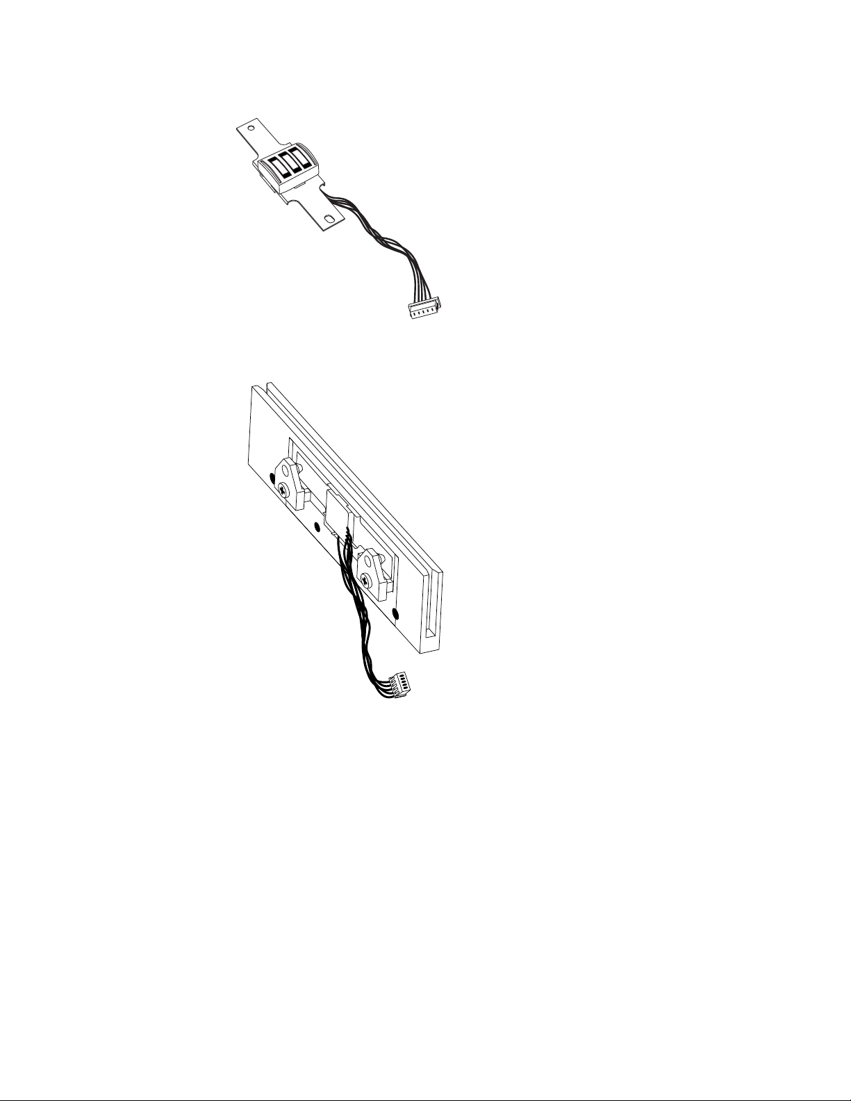
APPENDIX H. RS-232 INTELLIHEAD, SLIM PROFILE (PAX)
READER
Drawings
The following drawing is provided in this section:
Part Number Title
21047014 RS-232 IntelliHead, 3-Tracks 90mm Slim Profile (PAX), Cable 125mm 5-Pin
Molex
31
Page 38

Swipe Readers with RS-232 IntelliHead
Figure H-1. RS-232 IntelliHead, 90mm Slim Profile (PAX), 125mm, 5-Pin Molex Connector
32
 Loading...