

Page 1

SWIPE & PARK MT
HYBRID READER
TECHNICAL REFERENCE MANUAL
Manual Part Number 99875288-2
AUGUST 2006
REGISTERED TO ISO 9001:2000
1710 Apollo Court
Seal Beach, CA 90740
Phone: (562) 546-6400
FAX: (562) 546-6301
Technical Support: (651) 415-6800
www.magtek.com
Page 2

Cop 06
yright© 2001-20
MagTek®, Inc.
Printed in the United States of America
Information in this document is subject to change without notice. No part of this document may be
reproduced or transmitted in any form or by any means, e
lectronic or mechanical, for any purpose,
without the express written permission of MagTek, Inc.
MagTek is a registered trademark of MagTek, In
wipe & ParkTM is a trademark of MagTek, Inc.
S
c.
Patent is pending for Swipe & Park Hybrid Reader.
REVISIONS
Rev Number
1 19 Dec 03 Initial Release
2 21 Aug 06 -1085 in
Date Notes
Replaced obsolete Molex connector 71220-1000 with 52207
Mating Connectors; replaced drawing 21052178 with rev C
ii
Page 3

LIMITED WARRANTY
MagTek warrants that the products sold to Reseller pursuant to this Agreement will perform in accordance with
MagTek’s published specifications. This warranty shall be provided only for a period of one year from the da
of the shipment of the product from MagTek (the “Warranty Period”). This warranty shall apply only to the
original purchaser unless the buyer is au
shall apply only to the first repurchase.
thorized by MagTek to resell the products, in which event, this warranty
te
During the Warranty Period, should this product fail to conform to MagTek’s specifications, MagTek wi
option, repair or replace this product at no additional charge except as set forth below. Repair parts and
replacement products will be furnished on an exchange basis and will be either reconditioned or new. All rep
parts and products become the property of MagTek. This limited warranty does not include service to repair
damage to the product resulting from accident, disaster, unreasonable use, misuse, abuse, customer’s negligenc
Reseller’s negligence, or non-MagTek modification of the product. MagT
alleged defective goods to determine whether the warranty is applicable.
Without limiting the generality of the foregoing, MagTek specifically disclaims any liability or warranty for
goods resold in other than MagTek’s original packages, and for goods modified, altered, or treated by customers
Service may be obtained by delivering the product during the warranty period to MagTek (1710 Apollo Court,
Seal Beach, CA 90740). If this product is delivered by mail or by an equivalent shipping carrier, the customer
agrees to insure the product or assume the risk of loss or damage in transit, to prepay shipping charges to the
warranty service location and to use the original shipping container or equivalent. MagTek will return the produc
prepaid, via
all returns.
MAGTEK MAKES NO OTHER WARRANTY, EXPRESS OR IMPLIED, AND MAGTEK DISCLAIMS AN
WARRANTY OF ANY OTHER KIND, INCLU
FITNESS FOR A PARTICULAR PURPOSE.
EACH PURCHASER UNDERSTANDS THAT THE MAGTEK PRODUCT IS OFFERED AS IS. IF THIS
PRODUCT DOES NOT CONFORM TO MAGTEK’S SPECIFICATIONS, THE SOLE REMEDY SHALL BE
REPAIR OR REPLACEMENT AS PROVIDED ABOVE. MAGTEK’S LIABILITY, IF ANY, TO RESELLER
OR TO RESELLER’S CUSTOMERS, SHALL IN NO EVENT EXCEED THE TOTAL AMOUNT PAID TO
MAGTEK BY RESELLER UNDER THIS AGREEMENT. IN NO EVENT WILL MAGTEK BE LIABLE T
THE RESELLER OR THE RESELLER’S CUSTOMER FOR ANY DAMAGES, INCLUDING ANY LOST
PROFITS, LOST SAVINGS OR OTHER INCIDENTAL OR CONSEQUENTIAL DAMAGES ARISING OUT
OF THE USE OF OR INABILITY TO USE SUCH PRODUCT, EVEN IF MAGTEK HAS BEEN
T
HE POSSIBILITY OF SUCH DAMAGES, OR FOR ANY CLAIM BY ANY OTHER PARTY.
LIMITATION ON LIABILITY
a three (3) day shipping service. A Return Material Authorization (RMA) number must accompany
DING ANY WARRANTY OF MERCHANTABILITY OR
ek reserves the right to examine the
ll, at its
laced
e,
Y
O
ADVISED OF
.
t,
EXCEPT AS PROVIDED IN THE SECTIONS RELATING TO MAGTEK’S LIMITED WARRANTY,
MAGTEK’S L
PRODUCTS.
MAGTEK MAKES NO OTHER WARRANTIES WITH RESPECT TO THE PRODUCTS, EXPRESSED OR
IMPLIED, EXCEPT AS MAY BE STATED IN THIS AGREEMENT, AND MAGTEK DISCLAIMS A
IMPLIED WARRANTY, INCLUDING WITHOUT LIMITATION ANY IM
MERCHANTABILITY OR FITNESS FOR A PARTICULAR PURPOSE.
MAGTEK SHALL NOT BE LIABLE FOR CONTINGENT, INCIDENTAL, OR CONSEQUENTIAL
DAMAGES TO PERSONS OR PROPERTY. MAGTEK FURTHER LIMITS ITS LIABILITY OF ANY
WITH RESPECT TO THE PRODUCTS, I
CONTRACT PRICE FOR THE GOODS.
MAGTEK’S SOLE LIABILITY AND BUYER’S EXCLUSIVE REMEDIES ARE
AND IN THE SECTION RELATING TO MAGTEK’S LIMITED WARRANTY.
IABILITY UNDER THIS AGREEMENT IS LIMITED TO THE CONTRACT PRICE OF THE
NY
PLIED WARRANTY OF
KIND
NCLUDING ANY NEGLIGENCE ON ITS PART, TO THE
STATED IN THIS SECTION
iii
Page 4

TABLE OF CONTENTS
CTION 1. FEATURES AND SPECIFICATIONS.....................................................................................1
SE
CONFIGURATIONS .................................................................................................................................1
FEATURES...............................................................................................................................................1
APPLICABLE DOCUMENTS....................................................................................................................1
SPECIFICATIONS....................................................................................................................................2
SE
CTION 2. INSTALLATION......................................................................................................................5
MOUNTING ..............................................................................................................................................5
CABLES....................................................................................................................................................8
CTION 3. OPERATION AND MAINTENANCE......................................................................................9
SE
OPERATION.............................................................................................................................................9
MAINTENANCE......................................................................................................................................10
MATING CONNECTORS.......................................................................................................................10
APPENDIX A. ENGINEERING DRAWINGS.............................................................................................11
FIGURES
Figure 1-1. Swipe & Park MT Hybrid Reader............................................................................................... v
Figure 1-2. Reader Overall Dimensions.......................................................................................................3
Figure 2-1. Holes for Mounting Into Customer Enclosure............................................................................5
Figure 2-2. Optional PCB Mounting.............................................................................................................6
Figure 2-3. Spacers for PCB Mounting........................................................................................................6
Figure 2-4. Optional LED Mounting..............................................................................................................7
Figure 2-5. Position and Attachment of LED................................................................................................7
Figure 2-6. Flex Cable Pin 1 Location..........................................................................................................8
Figure 2-7. Flex Cable Pin List.....................................................................................................................8
Figure 2-8. Pitch and Mating Connector ......................................................................................................8
Figure 3-1. Magnetic Card Stripe Orientation and Components..................................................................9
Figure 3-2. Smart Card Orientation and Components...............................................................................10
Figure A-1. Read Head/Spring 2 Track......................................................................................................12
Figure A-2. Read Head/Spring 3 Track......................................................................................................13
TABLES
Table 1-1. Configuration...............................................................................................................................1
able 1-2. Specifications..............................................................................................................................2
T
iv
Page 5
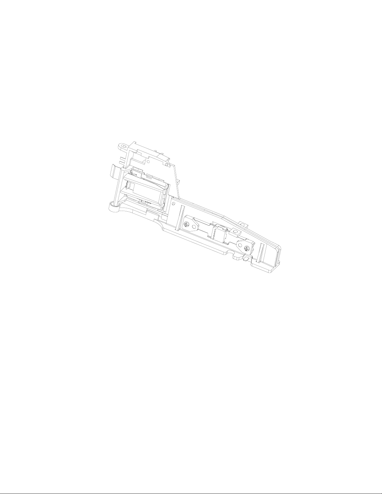
Figure 1-1. Swipe & Park MT Hybrid Reader
v
Page 6

Page 7

SECTION 1. FEATURES AND SPECIFICATIONS
The Swipe & Park MT Hybrid Reader supports both mag-stripe and smart card technologies.
For mag-stripe cards, the unit reads tracks 1 and 2, or tracks 1, 2, and 3. For smart cards, the unit
supports ICC 8-pin contacts for ISO smart cards.
CONFIGURATIONS
Configurations are listed in Table 1-1.
Table 1-1. Configuration
Part Number Head Head Position* Tracks Head Connector
21155003 Single Head Down/Left 1,2,3 J1
21155004 Single Head Down/Left 1,2 J1
* The magnetic stripe is inserted in the same orientation as the head position; for
example, head down/left means magnetic stripe down or to the left.
FEATURES
Features of the Swipe & Park Hybrid Reader are as follows:
• Unibody chassis that consists of a magnetic swipe path inline with a smart card reader
section
• Provides for mounting a dual or triple track magnetic read head in butterfly configuration
• Contains an 8-contact smart card block in ISO location
• Smooth swipe operation with minimal interference or obstruction to the user
• Mechanical detent keeps the card from sliding away from smart card contacts
• Proper clearance provided for bowed, warped, and embossed cards
• Rugged design for installation in harsh and high traffic environments
APPLICABLE DOCUMENTS
Documents applicable to the Swipe & Park Hybrid Reader are as follows:
ISO 7816-1, -2, -3 Identification Cards – Integrated circuits with contacts
ISO 7811-2, -3, -4, -5, -6 Identification Cards – Magstripe cards tracks 1-3
ISO 7810 Identification Cards – Physical Specifications
99821002 MagTek Reader Design Kit
99875148 I/O Interface for TTL Magnetic Swipe Readers, Technical
Reference Manual
1
Page 8

Swipe & Park MT Hybrid Reader
SPECIFICATIONS
Swipe & Park specifications are as shown in Table 1-2.
Table 1-2. Specifications
MECHANICAL
Dimensions
Overall Length:
Height:
Width:
Weight: 1.5 oz (42.5 gr)
Flammability Meets UL 94V-0
Temperature:
Operating:
Storage:
Humidity:
Operating:
Storage:
Altitude:
Operating:
Storage:
6.10” (155 mm)
2.34” (59 mm)
0.86” (22 mm)
ENVIRONMENTAL
o
0
C to 50 oC (32 oF to 122 oF)
o
-40
C to 70 oC (-40 oF to 158 oF)
5% to 90% non-condensing
5% to 90% non-condensing
0 to 10,000 ft. (0 to 3,048 m)
0 to 50,000 ft. (0 to 15,240 m)
The overall dimensions of the Reader are shown in Figure 1-2.
2
Page 9

Section 1. Features and Specifications
Figure 1-2. Reader Overall Dimensions
3
Page 10

Swipe & Park MT Hybrid Reader
4
Page 11

SECTION 2. INSTALLATION
The installation consists of mounting the Reader in a customer-supplied housing and connecting one cable
from the head and another from the Smart Card Block. Pin lists for the 2 track and 3 track heads are
shown in the drawings in Appendix A.
MOUNTING
The Reader is attached to a customer-supplied surface with three #4/M3 screws as indicated in Figure 2-1.
Brackets [ ] indicate millimeters; open numbers indicate inches.
Figure 2-1. Holes for Mounting Into Customer Enclosure
The optional PCB is attached with four spacers and four #4/M3 self-tapping screws. Positions of the
screw holes are indicated in Figure 2-2. Brackets [ ] indicate millimeters; open numbers indicate inches.
Spacers for minimum clearance to the chassis are shown in Figure 2-3.
5
Page 12

Swipe and Park MT Hybrid Reader
g
)
Figure 2-2. Optional PCB Mounting
If an optional PCB side mounting is to be used,
allow for a minimum clearance to the chassis.
Depending on the mounting holes selected, use
spacers 1, 2, or 3:
Minimum height for spacer 1 is .250” (6.35 mm)
Minimum height for spacer 2 is .83” (4.65 mm)
Minimum hei
ht for spacer 3 is .140” (3.56 mm
Figure 2-3. Spacers for PCB Mounting
6
Page 13

Section 2. Installation
The optional LED is attached with one #4/M3 self-tapping screw indicated in Figure 2-4. Brackets [ ]
indicate millimeters; open numbers indicate inches.
Figure 2-4. Optional LED Mounting
Figure 2-5 shows the position of the LED, the bracket that holds the LED in position, and the screw with
a maximum height of .175” (3.4 mm). The MagTek part number for the bracket is 30018905.
Figure 2-5. Position and Attachment of LED
7
Page 14

Swipe and Park MT Hybrid Reader
SWITCH
J2
CABLES
Figure 2-6 shows the location of Pin 1 on the flex cable with respect to the Reader. The pin list for the
flex cable is shown in Figure 2-7. Wiring for the head is shown in Appendix A.
Figure 2-6. Flex Cable Pin 1 Location
nCARDSEATED
SC_C8
SC_C7
SC_C6
SC_C1
SC_C2
SC_C3
SC_C4
Note: The Host Interface must provide
pull-up for card-seated switch.
Figure 2-7. Flex Cable Pin List
Figure 2-8 shows the pitch and mating connector of the flex cable:
.433" + .004" -.002"
.039" (1.0 mm pitch)
.012" x .012"
Chamfer or Radius
2 Places
110
.039" +/- .006"
Termination Detail.
Foil Side Shown.
Mates with Molex
71220 (or equivalent)
Scale: None
Figure 2-8. Pitch and Mating Connector
1
2
3
4
5
6
7
8
9
10
10PIN
8
Page 15

SECTION 3. OPERATION AND MAINTENANCE
OPERATION
Figures 3-1 and 3-2 show component parts and orientations of the magnetic stripe and smart card
contacts with respect to the Swipe & Park Reader.
Figure 3-1 shows the smart card contact block, the card-seated switch, the magnetic head
assembly, and the magnetic stripe on the card. The card-seated switch notifies the host that the
smart card is in position for reading. The pin lists for the head connectors are shown in
Appendix A.
Figure 3-1. Magnetic Card Stripe Orientation and Components
9
Page 16

Swipe and Park MT Hybrid Reader
Figure 3-2 shows the smart card block with flex cable, smart card block return spring, the card
stopper, and the contacts on the smart card.
Figure 3-2. Smart Card Orientation and Components
MAINTENANCE
The only maintenance required is for cleaning the customer-supplied enclosure, if required.
MATING CONNECTORS
Smartcard Flex Cable Connector, Molex 52807-1010 (through-hole) or 52207-1085 (SMT)
Read Head Mating Connector, Molex 53048-0710 (through-hole) or 53261-0790 (SMT)
10
Page 17

APPENDIX A. ENGINEERING DRAWINGS
The drawings in this section are as follows:
Part Number Description
21052179 Assembly, Read Head/Spring, 2Tk, Low Profile, 100mm
Wire and Connector
21052178 Assembly, Read Head/Spring, 3Tk, Low Profile, 100mm
Wire and Connector
11
Page 18

SmartSwipe Hybrid Reader
12
Figure A-1. Read Head/Spring 2 Track
Page 19

Appendix A. Engineering Drawings
Figure A-2. Read Head/Spring 3 Track
13
Page 20

Swipe and Park Hybrid Reader
14
 Loading...