

Page 1

SWIPE & PARK
HYBRID READER
TECHNICAL REFERENCE MANUAL
Manual Part Number 99875230-9
FEBRUARY 2009
REGISTERED TO ISO 9001:2000
1710 Apollo Court
Seal Beach, CA 90740
Phone: (562) 546-6400
FAX: (562) 546-6301
Technical Support: (651) 415-6800
www.magtek.com
Page 2

ii
Page 3

Copyright© 2001-2009
MagTek®, Inc.
Printed in the United States of America
Information in this document is subject to change without notice. No part of this document may be
reproduced or transmitted in any form or by any means, electronic or mechanical, for any purpose,
without the express written permission of MagTek, Inc.
MagTek is a registered trademark of MagTek, Inc.
Swipe & ParkTM is a trademark of MagTek, Inc.
Patent is pending for Swipe & Park Hybrid Reader.
REVISIONS
Rev Number Date Notes
1 20 Jun 02 Initial Release
2 24 Jun 02 Front Matter: Added Patent Pending to Copyright Page.
Section 3: To figure 3-2 added callout for “Circuit Board Mounting
Standoffs (5 Places)”.
3 06 Nov 02 Sec 1: Changed “Single or Dual Head” to “Head”.
4 13 Mar 03 Replaced some fonts so manual would print on all printers.
5 06 Jun 03 Throughout: Changed Title from SmartSwipe to Swipe & Park. Front
Matter: added ISO line to logo, changed Tech Support phone
number. Sec 2: added Figure 2-5, Pitch and Mating Connector.
6 16 Jul 03 Front Matter: modified limited warranty. Sec 1: Applicable
Documents, added ISO 7811-6 and I/O Interface manual and added
Flammability to Specifications. Sec 3: added mating connectors.
7 21 Aug 06 Front Matter: modified limited warranty. Replaced obsolete Molex
connector 71220-1000 with 52207-1085 in Mating Connectors;
replaced drawing 21052178 with rev C
8 25 Oct 07 Added 21155005
9 18 Feb 09 Removed 21155002 and the drawing of 21052179 since both are
obsolete
iii
Page 4

LIMITED WARRANTY
MagTek warrants that the products sold pursuant to this Agreement will perform in accordance with MagTek’s
published specifications. This warranty shall be provided only for a period of one year from the date of the
shipment of the product from MagTek (the “Warranty Period”). This warranty shall apply only to the “Buyer” (the
original purchaser, unless that entity resells the product as authorized by MagTek, in which event this warranty
shall apply only to the first repurchaser).
During the Warranty Period, should this product fail to conform to MagTek’s specifications, MagTek will, at its
option, repair or replace this product at no additional charge except as set forth below. Repair parts and
replacement products will be furnished on an exchange basis and will be either reconditioned or new. All replaced
parts and products become the property of MagTek. This limited warranty does not include service to repair
damage to the product resulting from accident, disaster, unreasonable use, misuse, abuse, negligence, or
modification of the product not authorized by MagTek. MagTek reserves the right to examine the alleged defective
goods to determine whether the warranty is applicable.
Without limiting the generality of the foregoing, MagTek specifically disclaims any liability or warranty for goods
resold in other than MagTek’s original packages, and for goods modified, altered, or treated without authorization
by MagTek.
Service may be obtained by delivering the product during the warranty period to MagTek (1710 Apollo Court, Seal
Beach, CA 90740). If this product is delivered by mail or by an equivalent shipping carrier, the customer agrees to
insure the product or assume the risk of loss or damage in transit, to prepay shipping charges to the warranty service
location, and to use the original shipping container or equivalent. MagTek will return the product, prepaid, via a
three (3) day shipping service. A Return Material Authorization (“RMA”) number must accompany all returns.
Buyers may obtain an RMA number by contacting Technical Support at (888) 624-8350.
EACH BUYER UNDERSTANDS THAT THIS MAGTEK PRODUCT IS OFFERED AS IS.
MAGTEK MAKES NO OTHER WARRANTY, EXPRESS OR IMPLIED, AND MAGTEK
DISCLAIMS ANY WARRANTY OF ANY OTHER KIND, INCLUDING ANY WARRANTY OF
MERCHANTABILITY OR FITNESS FOR A PARTICULAR PURPOSE.
IF THIS PRODUCT DOES NOT CONFORM TO MAGTEK’S SPECIFICATIONS, THE SOLE REMEDY
SHALL BE REPAIR OR REPLACEMENT AS PROVIDED ABOVE. MAGTEK’S LIABILITY, IF ANY,
SHALL IN NO EVENT EXCEED THE TOTAL AMOUNT PAID TO MAGTEK UNDER THIS AGREEMENT.
IN NO EVENT WILL MAGTEK BE LIABLE TO THE BUYER FOR ANY DAMAGES, INCLUDING ANY
LOST PROFITS, LOST SAVINGS, OR OTHER INCIDENTAL OR CONSEQUENTIAL DAMAGES ARISING
OUT OF THE USE OF, OR INABILITY TO USE, SUCH PRODUCT, EVEN IF MAGTEK HAS BEEN
ADVISED OF THE POSSIBILITY OF SUCH DAMAGES, OR FOR ANY CLAIM BY ANY OTHER PARTY.
LIMITATION ON LIABILITY
EXCEPT AS PROVIDED IN THE SECTIONS RELATING TO MAGTEK’S LIMITED WARRANTY,
MAGTEK’S LIABILITY UNDER THIS AGREEMENT IS LIMITED TO THE CONTRACT PRICE OF THIS
PRODUCT.
MAGTEK MAKES NO OTHER WARRANTIES WITH RESPECT TO THE PRODUCT, EXPRESSED OR
IMPLIED, EXCEPT AS MAY BE STATED IN THIS AGREEMENT, AND MAGTEK DISCLAIMS ANY
IMPLIED WARRANTY, INCLUDING WITHOUT LIMITATION ANY IMPLIED WARRANTY OF
MERCHANTABILITY OR FITNESS FOR A PARTICULAR PURPOSE.
MAGTEK SHALL NOT BE LIABLE FOR CONTINGENT, INCIDENTAL, OR CONSEQUENTIAL
DAMAGES TO PERSONS OR PROPERTY. MAGTEK FURTHER LIMITS ITS LIABILITY OF ANY KIND
WITH RESPECT TO THE PRODUCT, INCLUDING ANY NEGLIGENCE ON ITS PART, TO THE
CONTRACT PRICE FOR THE GOODS.
MAGTEK’S SOLE LIABILITY AND BUYER’S EXCLUSIVE REMEDIES ARE STATED IN THIS SECTION
AND IN THE SECTION RELATING TO MAGTEK’S LIMITED WARRANTY.
iv
Page 5

FCC WARNING STATEMENT
This equipment has been tested and was found to comply with the limits for a Class B digital device pursuant to
Part 15 of FCC Rules. These limits are designed to provide reasonable protection against harmful interference
when the equipment is operated in a residential environment. This equipment generates, uses, and can radiate radio
frequency energy and, if not installed and used in accordance with the instruction manual, may cause harmful
interference with radio communications. However, there is no guarantee that interference will not occur in a
particular installation.
FCC COMPLIANCE STATEMENT
This device complies with Part 15 of the FCC Rules. Operation of this device is subject to the following two
conditions: (1) this device may not cause harmful interference, and (2) this device must accept any interference
received, including interference that may cause undesired operation.
CANADIAN DOC STATEMENT
This digital apparatus does not exceed the Class B limits for radio noise from digital apparatus set out in the Radio
Interference Regulations of the Canadian Department of Communications.
Le présent appareil numérique n’émet pas de bruits radioélectriques dépassant les limites applicables aux appareils
numériques de la classe B prescrites dans le Réglement sur le brouillage radioélectrique édicté par le ministère des
Communications du Canada.
This Class B digital apparatus complies with Canadian ICES-003.
Cet appareil numériqué de la classe B est conformé à la norme NMB-003 du Canada.
CE STANDARDS
Testing for compliance with CE requirements was performed by an independent laboratory. The unit under test
was found compliant with standards established for Class B devices.
UL/CSA
This product is recognized per Underwriter Laboratories and Canadian Underwriter Laboratories 1950.
RoHS STATEMENT
When ordered as RoHS compliant, this product meets the Electrical and Electronic Equipment (EEE) Reduction of
Hazardous Substances (RoHS) European Directive 2002/95/EC. The marking is clearly recognizable, either as
written words like “Pb-free”, “lead-free”, or as another clear symbol ( ).
v
Page 6

TABLE OF CONTENTS
SECTION 1. FEATURES AND SPECIFICATIONS .................................................................................... 1
CONFIGURATIONS.................................................................................................................................
FEATURES ..............................................................................................................................................
ACCESSORIES........................................................................................................................................
RELATED DOCUMENTS.........................................................................................................................
SPECIFICATIONS.................................................................................................................................... 3
1
1
2
2
SECTION 2. INSTALLATION......................................................................................................................
MOUNTING..............................................................................................................................................
CABLES....................................................................................................................................................
SECTION 3. OPERATION AND MAINTENANCE......................................................................................
OPERATION ............................................................................................................................................
MAINTENANCE .....................................................................................................................................
MATING CONNECTORS.......................................................................................................................
APPENDIX A. ENGINEERING DRAWINGS.............................................................................................
5
5
7
9
9
10
10
11
TABLES and FIGURES
Figure 1-1. Swipe & Park Hybrid Reader....................................................................................................
Table 1-1. Configuration ..............................................................................................................................
Table 1-2. Specifications.............................................................................................................................. 3
Figure 2-1. Swipe & Park – Bottom View and Butterfly-Spring Side View ..................................................
Figure 2-2. Swipe & Park – Top View and Flex-Circuit Side View ..............................................................
Figure 2-3. Flex Cable Pin 1 Location .........................................................................................................
Figure 2-4. Flex Cable Pin List.....................................................................................................................
Figure 2-5. Pitch and Mating Connector......................................................................................................
Figure 3-1. Smart Card Contacts and Butterfly Spring Side of Swipe & Park Reader................................
Figure 3-2. Smart Card Bracket and Flex Cable Side of Swipe & Park Reader..........................................
Figure 4-1. Read Head / Spring 3 Track....................................................................................................
vii
1
5
6
7
7
7
9
9
12
vi
Page 7

Figure 1-1. Swipe & Park Hybrid Reader
vii
Page 8

viii
Page 9

SECTION 1. FEATURES AND SPECIFICATIONS
The Swipe & Park Hybrid Reader supports both mag-stripe and smart card technologies. For
mag-stripe cards, the unit reads tracks 1 and 2, or tracks 1, 2, and 3. For smart cards, the unit
supports ICC 8-pin contacts for ISO smart cards with flex circuit attached.
CONFIGURATIONS
Configurations are listed in Table 1-1.
Table 1-1. Configuration
Part Number Head Head Position Tracks Comments
21155001 Single Left Side 1,2,3 No Electronics
21155005 Single Left Side 1,2,3 Circuit Board with USB and RS-232 Interface
FEATURES
Features of the Swipe & Park Hybrid Reader are as follows:
• Continuous unibody chassis that consists of a magnetic swipe path in line with a smart
card reader section
• Provides for mounting a dual or triple track magnetic read head in butterfly configuration
• Contains an 8-contact smart card block in ISO location
• Smooth swipe operation with minimal interference or obstruction to the user
• Side pressure provided to keep the card from sliding away from smart card contacts
• Molded index pins provided that accurately allow for positioning of PCB
• Proper clearance provided for bowed, warped, and embossed cards
• Chassis mounting options
• Rugged design for installation in harsh and high traffic environments
And with the Electronics installed, the following additional features apply:
• On board SAM (Security Access Module)
• RS-232 and USB interfaces
• On board intelligence for transporting large blocks of data using a defined protocol and
command set
• Test LED
• Program Flash upgradeable
1
Page 10

Swipe & Park Hybrid Reader
ACCESSORIES
Other part numbers that may be included with the model with the PCB include the following:
Part
Number
16051408
16051430 USB-A to USB mini-B cable (white)
16051433 USB-A to USB mini-B cable (gray)
30037472 Demo Software, IntelliStripe Picture Demo (CD)
30037473 MagTek MCP Drivers (CD)
64300080
71100001
99510015 Demo Software, IntelliStripe Picture Demo (Web – ref www.magtek.com)
99510016 MagTek MCP Drivers (Web – ref www.magtek.com)
RS-232 / Power cable − 6 foot, Swipe & Park to 9-pin D female RS-232 and 2.5mm power
jack
Power Supply – Auto-ranging 100V-250V, regulated, 12VDC, 2.5mm plug. Requires
adapter to mate with power outlet; use Adapter/Power Cord (P/N 71100001) for North
American applications.
Power Outlet Adapter/Cord for North American applications (used with part number
64300080)
Description
RELATED DOCUMENTS
This document is from a hardware perspective only. Other MagTek documents that cover the
command set, communications protocol and API (Application Program Interface) are as follows:
Part Number Description
99821002 MagTek Reader Design Kit
99875161 IntelliStripe 65, Command Reference Manual
99875163 MCP, Serial Transport Protocol Reference Manual
99875164 MagTek Communication Protocol, Driver Reference Manual
Other documents applicable to the Swipe & Park Hybrid Reader are as follows:
ISO 7816-1, -2, -3 Identification Cards – Integrated circuits with contacts
ISO 7811-2, -3, -4, -5, -6 Identification Cards – Magstripe cards tracks 1-3
ISO 7810 Identification Cards – Physical Specifications
ISO Documents: 7810, 7811, 7816 are available from ANSI at:
Phone: 212-642-4900 or www.ansi.org
2
Page 11

Section 1. Features and Specifications
SPECIFICATIONS
Swipe & Park specifications are as shown in Table 1-2.
Table 1-2. Specifications
MECHANICAL
Dimensions:
Overall Length
Height
Width
Weight 2.31 oz (65.53 gr)
Flammability Meets UL 94V-0
Temperature:
Operating
Storage
Humidity:
Operating
Storage
Altitude:
Operating
Storage
DATA FORMAT SPECIFICATION – For PCB Model
Reader Configuration
Mag-Stripe Functions
Track 1,2,3 only
Smartcard Functions
Card Speed 3 IPS (7,62 cm/sec) to 50 IPS (127, cm/sec)
Recording Method Two-frequency coherent phase (F2F)
MTBF Head: 1,000,000 passes (500,000 Insertion Cycles)
Input Voltage
Current
* ISO (International Standards Organization), AAMVA, (American Association of Motor
Vehicle Administrators), JIS (Japanese Industrial Standard)
7.088” (177.8 mm)
2.632” (66.86 mm)
1.55” (39.4 mm)
ENVIRONMENTAL
o
-40
F to 122oF (-40o C to 50oC)
o
-40
F to 158oF (-40oC to 70oC)
5% to 90% non-condensing
5% to 90% non-condensing
0 to 10,000 ft. (0 to 3,048 m)
0 to 50,000 ft. (0 to 15,240 m)
Data Format Specification*
ISO/AAMVA/JIS formats
ISO 7810, 7811, JIS x 6302 Type 2
ISO 7816 T=0 and T=1 protocols, many popular memory cards
EMVCo Level 1 Approval
OPERATIONAL – For PCB Model
SC contacts: 1,000,000 insertions
ELECTRICAL – For PCB Model
12.0VDC ± 5%
500mA max, (1A with contactless smartcard option)
50mA idle, (300mA with contactless smartcard option)
3
Page 12

Swipe & Park Hybrid Reader
4
Page 13
SECTION 2. INSTALLATION
The installation consists of mounting the Reader in a customer-supplied housing and connecting
one cable from the head and another from the ICC contact. Pin lists for the 2 track and 3 track
heads are shown in the drawings in Appendix A.
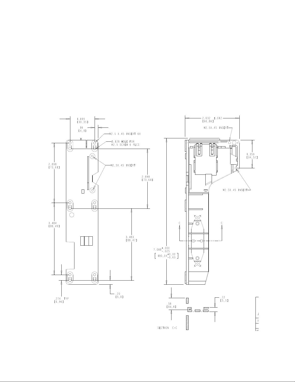
MOUNTING
The Reader is attached to a customer-supplied surface with six screws. The unit is attached
either from underneath into M2.5 inserts or from above with 2.5 screws. Positions of the inserts
and screw holes are shown in Figure 2-1, bottom view. Brackets [ ] indicate millimeters; open
numbers indicate inches.
Butterfly-Spring Side View
Bottom View
Figure 2-1. Swipe & Park – Bottom View and Butterfly-Spring Side View
5
Page 14

Swipe & Park Hybrid Reader
At the top of the Reader there are two springs and a bracket. These are used as a guide to funnel
the top of the card into the smart card section. A bracket and two springs hold the smart card in
position while the card is read. The guide and bracket provide the necessary side pressure to
keep the card under the smart card contacts and prevent the card from sliding away. The other
spring repositions the flex cable bracket when the card is removed. Brackets [ ] indicate
millimeters; open numbers indicate inches.
6
Flex-Circuit Side View Top View
Figure 2-2. Swipe & Park – Top View and Flex-Circuit Side View
Page 15

Section 2. Installation
SWITCH
J2
CABLES
Figure 2-3 shows the location of Pin 1 on the flex cable with respect to the Reader. The pin list
for the flex cable in shown in Figure 2-4. Wiring for the head is shown in Appendix A.
Figure 2-3. Flex Cable Pin 1 Location
nCARDSEATED
SC_C8
SC_C7
SC_C6
SC_C1
SC_C2
SC_C3
SC_C4
1
2
3
4
5
6
7
8
9
10
10PIN
Note: The Host Interface must provide pull-up for card-seated switch.
Figure 2-4. Flex Cable Pin List
Figure 2-5 shows the pitch and mating connector of the flex cable:
.433" + .004" -.002"
.039" (1.0 mm pitch)
.012" x .012"
Chamfer or Radius
2 Places
110
.039" +/- .006"
Termination Detail.
Foil Side Shown.
Mates with Molex
71220 (or equivalent)
Scale: None
Figure 2-5. Pitch and Mating Connector
7
Page 16

Swipe & Park Hybrid Reader
8
Page 17

SECTION 3. OPERATION AND MAINTENANCE
OPERATION
Component parts and orientation of the Swipe & Park Reader are shown in Figures 3-1 and 3-2.
Card Holding And
Positioning Spring
Card-Seated
Contact
8-Contact
Smart Card
Block
And Bracket
Butterfly Spring
Head Wiring
Figure 3-1. Smart Card Contacts and Butterfly Spring Side of Swipe & Park Reader
Smart Card
Contacts
Circuit Board
Mounting Standoffs
(5 places)
Flex Circuit
Pin 1
Pin 10
Head Connector
Spring T o Disengage
Smart Card Bracket
Smart Card Bracket
And flex Cable
Figure 3-2. Smart Card Bracket and Flex Cable Side of Swipe & Park Reader
9
Page 18

Swipe & Park Hybrid Reader
In Figure 3-1, the orientation of the magnetic stripe is that it faces toward the viewer, and the
smart card contacts face away from the viewer. In Figure 3-2 the orientation is the opposite: the
magnetic stripe faces away from the viewer, and the smart card contacts face toward the viewer.
Figure 3-1 shows the smart card contacts, the card-seated contact, the butterfly spring, the head
wiring and the card holding and positioning spring and bracket. The card-seated contact notifies
the host that the smart card is in position for reading. The butterfly spring is for more accurate
reading of bowed or warped cards. The pin lists for the head connectors are shown in Appendix
A. The card holding and positioning spring and bracket provide the necessary pressure to keep
the card under the smart card contacts and prevent it from sliding away.
Figure 3-2 shows the smart card contacts with respect to the smart card bracket and flex cable,
the pin orientation on the flex cable, the head connector, and the bracket disengagement spring.
The disengagement spring repositions the flex cable bracket when the card is removed. Also
shown are the five circuit board mounting standoffs.
MAINTENANCE
The only maintenance required is for cleaning the customer-supplied enclosure.
MATING CONNECTORS
For models without electronics:
• Smartcard Flex Cable Connector, Molex 52807-1010 (through-hole) or 52207-1085
(SMT)
• Read Head Mating Connector, Molex 53048-0710 (through-hole) or 53261-0790 (SMT)
For models with electronics:
• See Accessories table
10
Page 19

APPENDIX A. ENGINEERING DRAWINGS
The drawings in this section are as follows:
Part Number Description
21052178 Assembly, Read Head/Spring, 3Tk, Low Profile,100mm Wire and Connector
11
Page 20

SmartSwipe Hybrid Reader
Figure 4-1. Read Head / Spring 3 Track
12
 Loading...