

Page 1
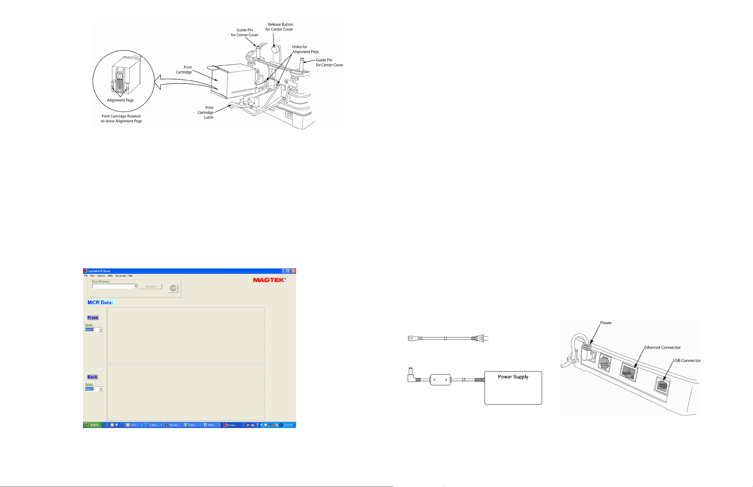
Figure 4. Rear Print Cartridge Installation/Removal
5. RUN EXCELLA DEMO
• Click on the Excella Demo icon to run the demo.
• The Demo’s main screen will be displayed (see Figure 5 below).
• In the “Select Device” window, choose the device you want to connect (USB or Ethernet).
• Click on the “Connect” button.
• Based on the document you want to read, click on one of these buttons:
o “Check”, to read and scan checks (the left LED is blinking)
o “Card”, to read and scan ID cards (the right LED is blinking)
o “Check/Card”, the unit will accept either a check or a card (both LED’s blinking)
• Feed the appropriate document.
• The unit will remain in the Read/Scan mode until the “Stop” button is clicked.
P/N 99875344-2.03 09/06
EXCELLA STX INSTALLATION GUIDE
(RNDIS USB Drivers or Ethernet Only)
1. START
• For USB, go to Step 2 below
• For Ethernet, got to Step 3 below
2. USB INSTALLATION
Software Installation
• Remove earlier versions of the demo using the PC’s Add or Remove Programs.
• Insert Excella STX’s Software & Drivers CD in drive; the CD will run automatically.
• Follow the wizard instructions to install the software and use the default directories.
• When prompted by the Wizard, select option (a) and (b) below to install the Excella STX Demo and API;
to skip the Excella STX Demo and only install the API and MagTek USB Drivers, select option (b) only:
(a) Excella STX Demo and API (Demo requires drivers for USB Devices)
(b) Excella STX USB Driver and API
• When done, click on Finish to complete the installation process.
• NOTE: The default destination folder is C:\Program Files\MagTek\Excella-STX\
Connect cables
• Connect interface USB cable to Excella STX (refer to Figure 1 below).
• Connect round connector from the power supply to Excella.
• Connect the power cord to the socket on the power supply block.
• Connect the three-prong power cord to AC wall outlet.
• Wait until only the middle LED is illuminated with a steady green.
• Connect interface cable to PC.
• NOTE: When the device is plugged in and detected by the PC, the USB drivers will be automatically
installed.
Power Cord
Figure 1. Cables & Connectors
Page 4 of 4 Page 1 of 4
Page 2
Device Address Setup
• Using My Computer go to the folder C:\program files\Magtek\Excella-STX.
• Run the ExcellaUSBConfig.exe program (see Figure 2 below)
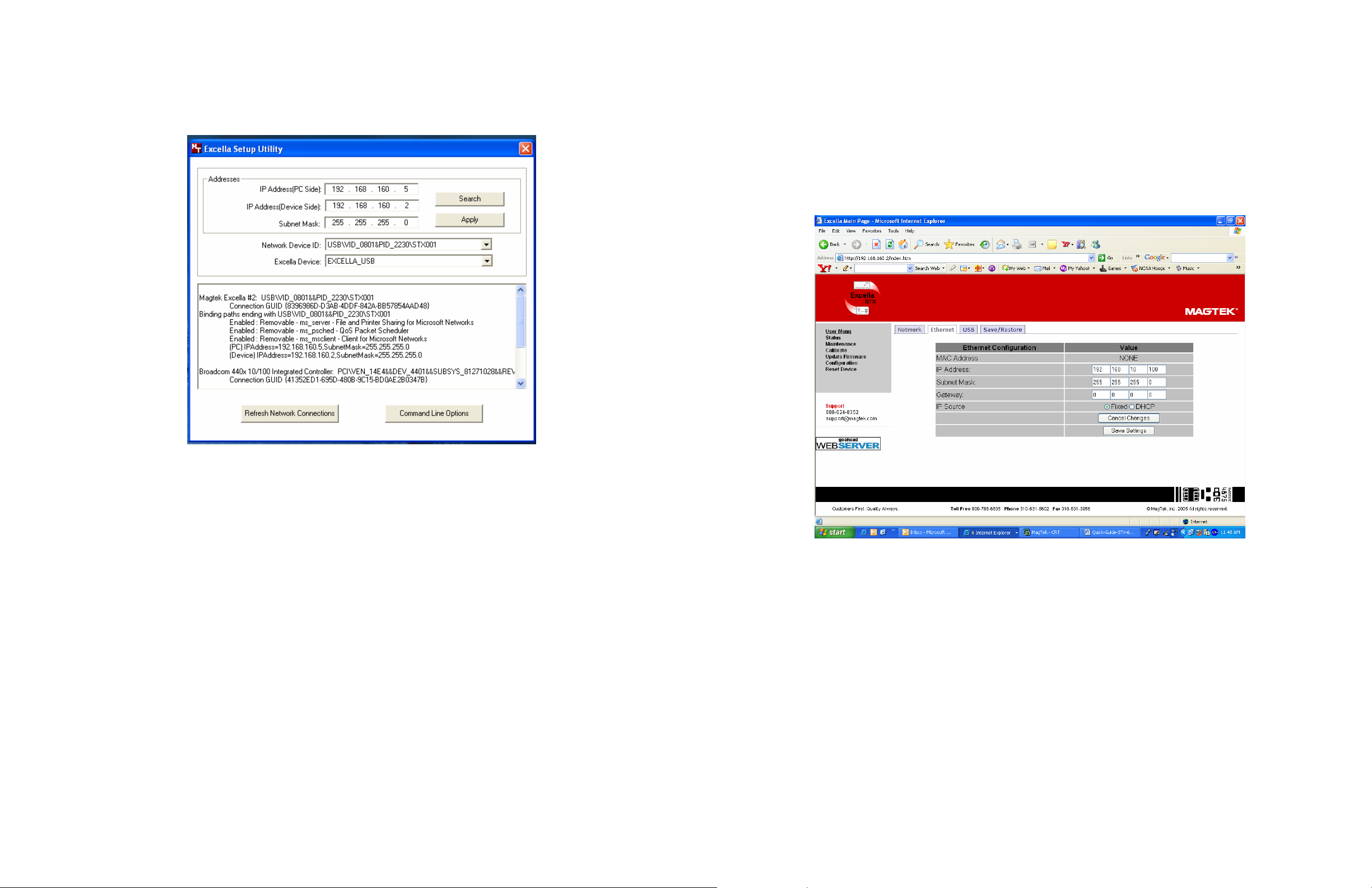
Ethernet Configuration
• In your web browser, type Excella STX’s default Ethernet IP address as follows: http://192.168.10.100;
Excella STX’s built-in web page will be displayed.
• In the User Menu, click on Configuration.
• Select the Ethernet tab and configure all parameters shown (see Figure 3 below).
• Click on Save Settings and close the web browser.
• Continue to Step 4, INSTALL INK CARTRIDGE(S) below.
Figure 2. Excella Setup Utility Screen
• For Subnet Mask, Network Device ID and Excella Device, accept the defaults shown.
• Click once on the Search button (this will automatically fill in valid IP addresses).
• Click on the Apply button.
• Click OK.
• Close this program.
• Continue to Step 4, INSTALL INK CARTRIDGE(S) below.
3. ETHERNET INSTALLATION
Connect cables
• Connect Ethernet interface cable, USB to Excella STX (refer to Figure 1 above).
• Connect round connector from the power supply to Excella.
• Connect the power cord to the socket on the power supply block.
• Connect the three-prong power cord to AC wall outlet.
• Wait until only the middle LED is illuminated with a steady green.
• Connect interface cable to PC.
Figure 3. Ethernet Configuration Screen
4. INSTALL INK CARTRIDGE(S)
• Remove the outer cover by pressing the release buttons on each side and lifting the cover.
• Remove the center cover by pressing the rear/front release buttons and lifting the cover.
• Ensure the printer latch is down and locate the alignment pegs on the Printer/Cartridge and the guide
holes in the Printer Base (see Figure 4 below).
• Slide the alignment pegs into the guide holes as indicated in the figure below.
• Raise the latch so that it touches the Printer/Cartridge.
• Press the latch into the lock position, and move the Cartridge slightly to ensure it is locked.
• If needed, perform steps 1-4 on the Front Printer/Cartridge located inside of the exit path.
Figure 4. Rear Print Cartridge Installation/Removal
Page 2 of 4 Page 3 of 4
 Loading...