

Page 1

EXCELLA STX
MICR CHECK REA DER
AND DUAL-SIDED SCANNER
INSTALLATION AND OPERATION MANUAL
Part Number: 99875342-1
FEBRUARY 2013
REGISTERED TO ISO 9001:2008
1710 Apollo Court
Seal Beach, CA 90740
Phone: (562) 546-6400
FAX: (562) 546-6301
Technical Support: (651) 415-6800
www.magtek.com
Page 2
ii
Rev Number
Date
Notes
1
30 Mar 06
Initial Release
Copyright© 2004 - 2013
MagTek®, Inc.
Printed in the United States of Americ a
Information in this document is subject to change without notice. No part of this document may
be reproduced or transmitted in any form or by any means, electronic or mechanical, for any
purpose, without the express written permission of MagTek, Inc.
MagTek is a registered trademark of MagTek, Inc.
Excella STXTM is a trademark of MagTek, Inc.
MagnePrintTM is a trademark of MagTek, Inc.
REVISIONS
Page 3

iii
LIMITED WARRANTY
MagTek warrants that the products sold to Reseller pursuant to this Agreement will perform in accordance with
MagTek’s published specifications. This warranty shall be provided only for a period of one year from the date of
the shipment of the product from MagTek (the “Warranty Period”). This warranty shall apply only to the original
purchaser unless the buyer is authorized by MagTek to resell the products, in which event, this warranty shall apply
only to the first repurchase.
During the Warranty Period, should this product fail to conform to MagTek’s specifications, MagTek will, at its
option, repair or replace this product at no add ition al charge except as set forth below. Repair parts and
replacement products will be furnished on an exchange basis and will be either reconditioned or new. All replaced
parts and products become the property of MagTek. This limited warranty does not include service to repair
damage to the product resulting from accident, disaster, unreasonable use, misuse, abuse, customer’s negligence,
Reseller’s negligence, or non-MagTek modification of the product. MagTek reserves the right to examine the
alleged defective goods to determine whether the warranty is applicable.
Without limiting the generality of the foregoing, MagTek specifically disclaims any liability or warranty for goods
resold in other than MagTek’s original packages, and for goods modified, altered, or treated by customers.
Service may be obtained by delivering the product during the warranty period to MagTek (1710 Apollo Court, Seal
Beach, CA 90740). If this product is delivered by mail or by an equivalent shipping carrier, the customer agrees to
insure the product or assume the risk of loss or damage in transit, to prepay shipping charges to the warranty service
location and to use the original shipping container or equivalent. MagTek will return the product, prepaid, via a
three (3) day shipping service. A Return Material Authorization (RMA) number must accompany all returns.
MAGTEK MAKES NO OTHER WARRANTY, EXPRESS OR IMPLIED, AND MAGTEK DISCLAIMS ANY
WARRANTY OF ANY OTHER KIND, INCLUDING ANY WARRANTY OF MERCHANTABILITY OR
FITNESS FOR A PARTICULAR PURPOSE.
EACH PURCHASER UNDERSTANDS THAT THE MAGTEK PRODUCT IS OFFERED AS IS. IF THIS
PRODUCT DOES NOT CONFORM TO MAGTEK’S SPECIFICATIONS, THE SOLE REMEDY SHALL BE
REPAIR OR REPLACEMENT AS PROVIDED ABOVE. MAGTEK’S LIABILITY, IF ANY, TO RESELLER
OR TO RESELLER’S CUSTOMERS, SHALL IN NO EVENT EXCEED THE TOTAL AMOUNT PAID TO
MAGTEK BY RESELLER UNDER THIS AGREEMENT. IN NO EVENT WILL MAGTEK BE LIABLE TO
THE RESELLER OR THE RESELLER’S CUSTOMER FOR ANY DAMAGES, INCLUDING ANY LOST
PROFITS, LOST SAVINGS OR OTHER INCIDENTAL OR CONSEQUENTIAL DAMAGES ARISING OUT
OF THE USE OF OR INABILITY TO USE SUCH PRODUCT, EVEN IF MAGTEK HAS BEEN ADVISED OF
THE POSSIBILITY OF SUCH DAMAGES, OR FOR ANY CLAIM BY ANY OTHER PARTY.
LIMITATION ON LIABILITY
EXCEPT AS PROVIDED IN THE SECTIONS RELATING TO MAGTEK’S LIMITED WARRANTY,
MAGTEK’S LIABILITY UNDER THIS AGREEMENT IS LIMITED TO THE CONTRACT PRICE OF THE
PRODUCTS.
MAGTEK MAKES NO OTHER WARRANTIES WITH RESPECT TO THE PRODUCTS, EXPRESSED OR
IMPLIED, EXCEPT AS MAY BE STATED IN THIS AGREEMENT, AND MAGTEK DISCLAIMS ANY
IMPLIED WARRANTY, INCLUDING WITHOUT LIMITATION ANY IMPLIED WARRANTY OF
MERCHANTABILITY OR FITNESS FOR A PARTICULAR PURPOSE.
MAGTEK SHALL NOT BE LIABLE FOR CONTINGENT, INCIDENTAL, OR CONSEQUENTIAL
DAMAGES TO PERSONS OR PROPERTY. MAGTEK FURTHER LIMITS ITS LIABILITY OF ANY KIND
WITH RESPECT TO THE PRODUCTS, INCLUDING ANY NEGLIGENCE ON ITS PART, TO THE
CONTRACT PRICE FOR THE GOODS.
MAGTEK’S SOLE LIABILITY AND BUYER’S EXCLUSIVE REMEDIES ARE STATED IN THIS SECTION
AND IN THE SECTION RELATING TO MAGTEK’S LIMITED WARRANTY.
Page 4

iv
Agency approvals are pending:
FCC WARNING STATEMENT
This equipment has been tested and found to comply with the limits for a Class A digital device, pursuant
to Part 15 of FCC Rules. These limits are designed to provide reasonable protection against harmful
interference when the equipment is operated in a commercial environment. This equipment generates,
uses, and can radiate radio frequency energy and, if not installed and used in accordance with the
instruction manual, may cause harmful interference to radio communications. Operation of this
equipment in a residential area is likely to cause harmful interference in which case the user will be
required to correct the interference at his own exp ense.
FCC COMPLIANCE STATEMENT
This device complies with Part 15 Of The FCC Rules. Operation of this device is subject to the following
two conditions: (1) This device may not cause harmful interference. And (2) This device must accept any
interference received, including interference that may cause undesired operation.
CANADIAN DOC STATEMENT
This digital apparatus does not exceed the Class A limits for radio noise for digital apparatus set out in the
Radio Interference Regulations of the Canadian Department of Communications.
Le présent appareil numérique n’émet pas de bruits radioélectriques dépassant les limites applicables
aux appareils numériques de las classe A prescrites dans le Réglement sur le brouillage radioélectrique
édicté par les ministère des Communications du Canada.
This Class A digital apparatus c omplies with Canadian ICES-003.
Cet appareil numériqué de la classe A est conformé à la norme NMB-003 du Canada.
CE STANDARDS
Testing for compliance to CE was performed by an independent laboratory. The unit under test was
found compliant to Class A.
UL/CSA
This product is listed per Underwriter Laboratories and Canadian Underwriter Laboratories 1950.
Page 5

v
TABLE OF CONTENTS
SECTION 1. FEATURES AND SPECIFICATIONS .................................................................................... 1
CONFIGURATIONS ................................................................................................................................. 1
REQUIREMENTS ..................................................................................................................................... 1
FEATURES ............................................................................................................................................... 1
ACCESSORIES ........................................................................................................................................ 2
SPECIFICATIONS .................................................................................................................................... 2
SECTION 2. INSTALLATION ...................................................................................................................... 5
INSTALLATION SUMMARY ..................................................................................................................... 5
COVER REMOVAL .................................................................................................................................. 5
Outer Cover Removal ........................................................................................................................... 6
Center Cover Removal ......................................................................................................................... 7
PRINTER/CARTRIDGE INSTALLATION AND REMOVAL ...................................................................... 8
Printer/Cartridge Installation ................................................................................................................. 8
Center Cover Replacement .................................................................................................................. 9
Outer Cover Replacement .................................................................................................................... 9
CABLE CONNECTIONS ........................................................................................................................ 10
CABLING ................................................................................................................................................ 10
SECTION 3. OPERATION AND MAINTENANCE .................................................................................... 13
POWER UP ............................................................................................................................................ 13
OPERATION ........................................................................................................................................... 13
Check Insertion ................................................................................................................................... 13
ID Card Insertion ................................................................................................................................ 14
LED Locations and Descriptions ........................................................................................................ 14
MAINTENANCE ...................................................................................................................................... 16
Printer/Cartridge Cleaning .................................................................................................................. 16
Scan Bar Cleaning.............................................................................................................................. 17
Card and Check Path Cleaning .......................................................................................................... 19
APPENDIX A. BUILT-IN WEB PAGE ........................................................................................................ 21
OVERVIEW ............................................................................................................................................. 21
STATUS .................................................................................................................................................. 21
MAINTENANCE ...................................................................................................................................... 22
CALIBRATE ............................................................................................................................................ 22
UPDATE FIRMWARE ............................................................................................................................. 23
CONFIGURATION .................................................................................................................................. 24
Network Configuration Tab ................................................................................................................. 25
Ethernet Configuration Tab ................................................................................................................ 26
USB Configuration Tab ...................................................................................................................... 28
Save/Restore Configuration Tab ........................................................................................................ 29
RESET DEVICE...................................................................................................................................... 30
APPENDIX B. USB CONFIGURATION UTILITY ..................................................................................... 31
OVERVIEW ............................................................................................................................................. 31
DEVICE ADDRESS S ETUP ................................................................................................................... 32
APPENDIX C. CHECK READING ............................................................................................................. 33
E13-B CHARACTER SET ...................................................................................................................... 33
CMC-7 CHARACTER SET ..................................................................................................................... 33
CHECK LAYOUTS ................................................................................................................................. 34
MICR FIELDS ......................................................................................................................................... 35
1-Transit Field ..................................................................................................................................... 35
2-On-Us Field ..................................................................................................................................... 36
Page 6

vi
3-Amount Field ................................................................................................................................... 36
4-Auxiliary On-Us Field ...................................................................................................................... 36
APPENDIX D. LICENSE AND COPYRIGHT ............................................................................................ 37
Page 7

vii
TABLES AND FIGURES
Figure 1-1. Excella STX ............................................................................................................................. viii
Table 1-1. Specifications .............................................................................................................................. 3
Figure 2-1. Outer Cover Removal ................................................................................................................ 6
Figure 2-2. Center Cover Removal .............................................................................................................. 7
Figure 2-4. Printer/Cartridge Installation and Removal ................................................................................ 9
Figure 2-5. Cable Connections .................................................................................................................. 10
Figure 2-6. Power Supply and Cords. P/N 64300098 and 71100001 ...................................................... 10
Figure 2-7. Cabling, USB, 4-pin, P/N 22350300 ........................................................................................ 11
Figure 2-8. Cabling, Ethernet P/N22350302 .............................................................................................. 11
Figure 3-1. Position for Holding and Entering Check ................................................................................. 13
Figure 3-2. Position for Holding and Entering ID Card .............................................................................. 14
Figure3-3. MSR Card Insertion .................................................................................................................. 14
Figure 3-4. Location of LED Indicators ...................................................................................................... 15
Table 3-1. Description of LEDs .................................................................................................................. 15
Figure 3-5. Cleaning the Ink Cartridge ....................................................................................................... 16
Figure 3-6. Opening Left Scan Bar ............................................................................................................ 17
Figure 3-7. Opening Right Scan Bar .......................................................................................................... 18
Figure 3-8. Cleaning the Scan Bars ........................................................................................................... 19
Figure A-1. Excella STX Status Page ........................................................................................................ 21
Figure A-2. Maintenance Page .................................................................................................................. 22
Figure A-3. Update Firmware Page ........................................................................................................... 23
Figure A-4. Network Configuration Tab ..................................................................................................... 25
Figure A-5. Ethernet Configuration Tab ..................................................................................................... 26
Figure A-6. USB Configuration Tab ........................................................................................................... 28
Figure A-7. Save/Restore Configuration Tab ............................................................................................. 29
Figure B-1. ExcellaUSBConfig Utility Screen ............................................................................................. 31
Table C-1. CMC-7 Nonnumeric Characters ............................................................................................... 34
Figure C-1. Personal Checks .................................................................................................................... 34
Figure C-2. Business Checks..................................................................................................................... 35
Page 8

viii
Figure 1-1. Excella STX
Page 9

1
Part Number
Description
22350001
MICR EXCELLA STX USB/ETH COLR MSR FPRT BPRT
22350002
MICR EXCELLA STX USB/ETH COLR MSR FPRT BPRT W/DEV KIT
22350003
MICR EXCELLA ST X USB/ETH GRAY MSR
22350004
MICR EXCELLA STX USB/ETH GRAY FPRT BPRT
22350005
MICR EXCELLA STX USB/ETH GRAY MSR FPRT BPRT
22350006
MICR EXCELLA STX USB/ETH GRAY FPRT
22350007
MICR EXCELLA STX USB/ETH GRAY BPRT
SECTION 1. FEATURES AND SPECIFICATIONS
The Excella STXTM Check Reader is a MICR check reader (Magnetic Ink Character
Recognition) and dual-sided scanner with endorsement printer. The Excella STX is a single
transaction Check Reader; one check is entered into the Excella STX at a time. The Excella STX
reads the MICR character set (E13B or CMC7 fonts) on the front face and bottom of a check and
scans both sides of the check in a single pass, producing high-quality, grayscale or black/white
images (color images are offered as an option) in the most common file formats used in the
industry. The characters and the image are then transmitted to a Host device.
Excella STX will communicate with the Host system using a USB 2.0 or Ethernet interface.
CONFIGURATIONS
The current configuration is as follows:
REQUIREMENTS
The following items are required for the Installation:
• Excella STX, Check Reader and Dual-Sided Scanner
• USB Interface Cable (P/N 22350300) or
• Ethernet Interface Cable (P/N 22350302)
• Power Supply, 24 VDC Regulated, Switcher, 5.5 x 2.1 mm, Right Angle Plug, P/N 64300098
• API/Demo software CD
FEATURES
The following is a list of features of the Excella Reader:
• Check Reader Reads E13B and CMC7 MICR fonts
• Captures front and back images of check in a single pass
• Optional printers print horizontal message on front or back of the check
Page 10

Excella STX Installation and Opera tion
2
STX accessories P/N listing
Description
22350300
COM USB 2.0 A-B BLK 6’
22350301
COM USB 2.0 A-B BLK 10’
22350302
COM ETHERNET CAT5E BLK 10’
22350303
COM ETHERNET CAT5E GRAY XOVER 10’
93600132
COM PRINTER PART,HP C6602A INKJET CARTRIDGE BLK
64300098
PWR SUP 24VDC REG SW 5.5X2.1MM R/A PLG,3WR AC
71100001
CBL POWER CORD-AC, US 18/3 10A SVT 7’ BLK
22359069
DEMO SOFTW AR E
965300XX
Sample Checks, Pack of 5
97200033
Cleaning Swabs
• Printed messages are programmable
• Message height: 1/8” consisting of 12 pixels
• Resolution: 200 dpi (scaling to 100 dpi); black/white and grayscale images
• Image compression: CCITT G4 or JPEG
• Image files: TIFF 6.0, JFIF with EXIF tags, BMP
• Manual feed - single check
• USB 2.0 High Speed (USB 1.1 compatible)
• Ethernet 10/100 Base-T
• Smart cable management
• Magnetic Stripe Reader with MagnePrint
ACCESSORIES
Accessories available for the Excella Reader include the following:
TM
SPECIFICATIONS
The specifications for the STX are listed in Table 1-1.
Page 11
Section 1. Features and Specifica tions
3
OPERATING
Check Reader
Reference Standards
ANSI X9.27
Power Input
24 VDC, 2.5 Amps
Document Size
4”x 8.5” Maximum
Printer/Cartridge
Image compression:
CCITT G4 or JPEG
Check Feed:
Manual feed of a single check
MICR fonts supported
E13-B
CMC-7
Ethernet 100 Base-T,
Magnetic Stripe Reader
Reference Standards
ISO 7810 and ISO 7811/ AAMVA*
Message Format
ASCII
Card Speed
4 to 60 ips (10.1 to 152.4 cm/s)
MECHANICAL
Dimensions
L 13 ¼ inches x W 7 ½ inches; H 7 inches
Weight
3.59 lbs.
Table 1-1. Specifications
Image Resolution:
Interface Options RS-232,
*ISO (International Standards Organization) and AAMVA (American Association of Motor Vehicle
Administrators).
200 dpi (scaling to 100 dpi); Black/white and grayscale images (color
images are offered as an option)
USB 2.0, USB 1.1 compatible
Page 12

Excella STX Installation and Opera tion
4
Page 13

5
SECTION 2. INSTALLATION
This section describes the Installation of the Excella STX.
INSTALLATION SUMMARY
A summary of the major installation steps for Excella STX follows:
1. Unpack Excella STX
2. Remove two covers and install 2 ink cartridges (the cartridges are shipped uninstalled)
3. Install Excella STX API/Demo software (CD provided by MagTek)
4. Connect interface cable (USB or Ethernet) and power cable to Excella STX
5. Connect power cord to AC wall outlet
6. Connect interface cable to PC
7. When using the USB interface, run the “ExcellaUSBConfig” utility (see Appendix B) to
establish a connection between the PC and Excella STX.
COVER REMOVAL
Two covers must be removed before the two Printer/Cartridges can be installed. Proceed as
follows:
Page 14
Excella STX Installation and Opera tion
6
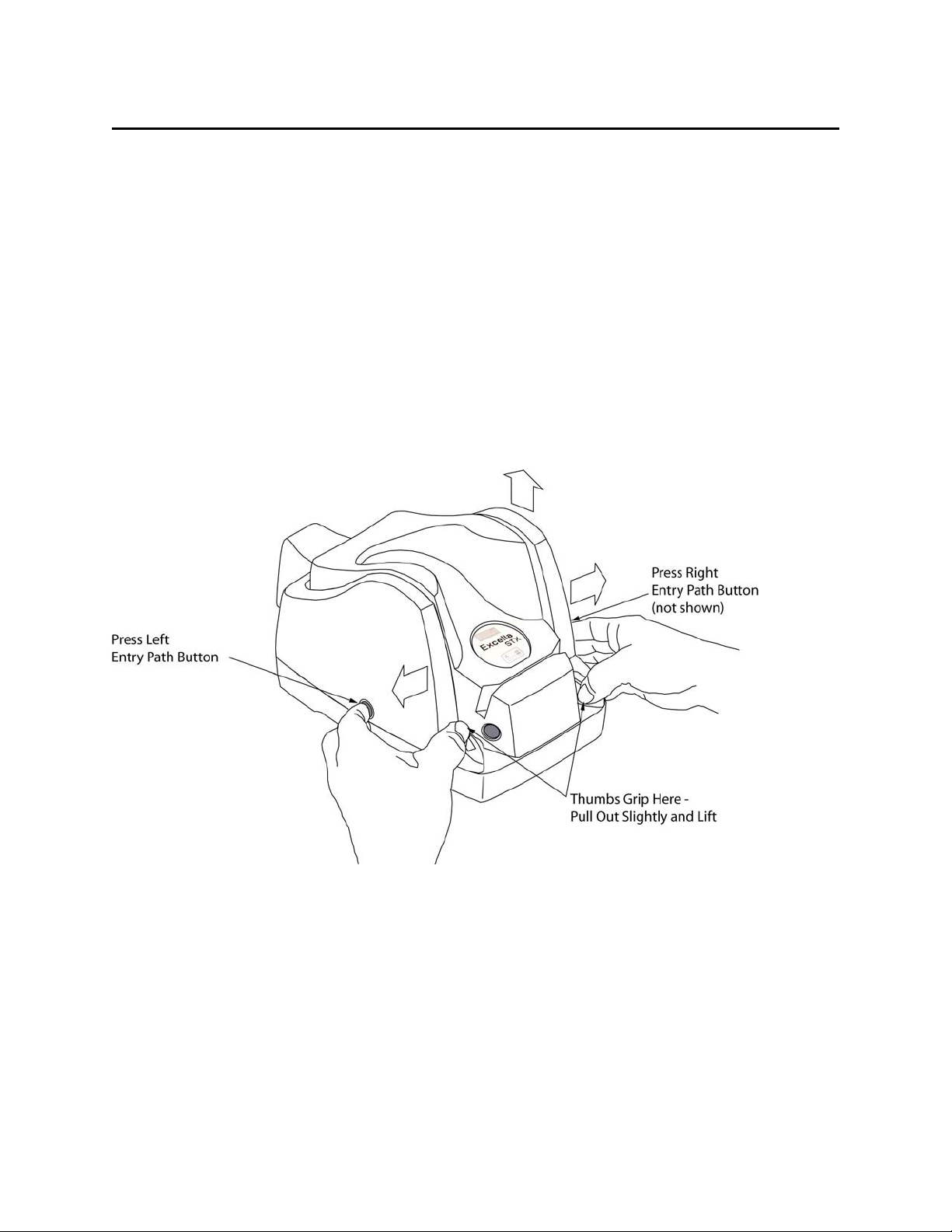
Outer Cover Removal
To remove the Outer Cover, perform the following:
1. Using both hands, place two index fingers on the release buttons and two thumbs on the inner
race of the Outer Cover as shown in Figure 2-1. (The left Release Button is shown; the
Right Release Button is directly opposite.)
2. As indicated in the illustration, press the two Release Buttons in, and at the same time
slightly pull the two inner race segments out until the cover detaches.
3. Lift the Outer Cover to remove it from the assembly.
Figure 2-1. Outer Cover Removal
Page 15
Section 2. Installation
7
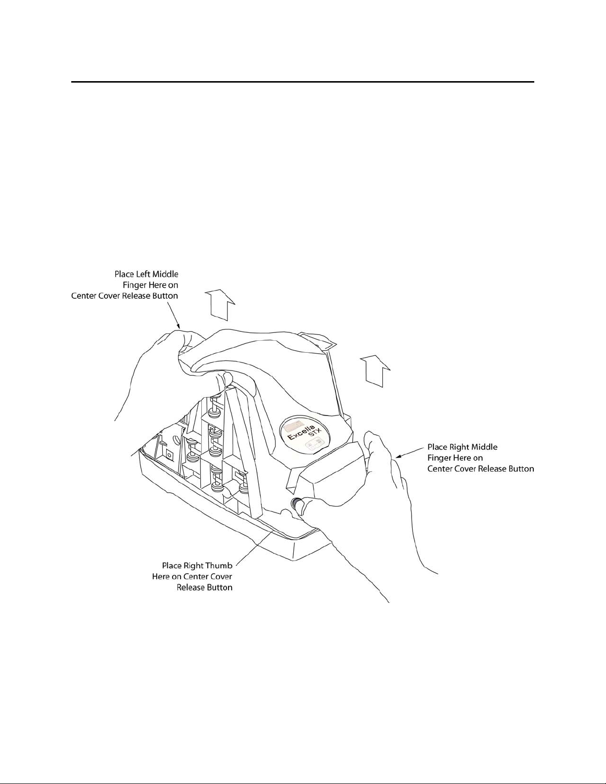
Center Cover Removal
To remove the Center Cover, perform the following:
1. Place the right-hand thumb and index finger on the front Release Buttons as indicated in
Figure 2-2.
2. Place the index finger on the rear Release Button (not shown) as indicated in the illustration.
(The location of the rear Release Button is shown in Figure 2-3.)
3. Press all three buttons and lift the cover at the same time until the cover detaches.
Figure 2-2. Center Cover Removal
Page 16

Excella STX Installation and Opera tion
8
PRINTER/CARTRIDGE INSTALLATION AND REMOVAL
Printer/Cartridge Installation
To install the Printer/Cartridge, refer to Figure 2-4 and perform the following:
1. Ensure the printer latch is down and locate the guide pins on the Printer/Cartridge and the
guide holes in the Printer Base (Inset).
2. Slide the guide pegs into the guide holes as indicted in Figure 2-4.
3. Raise the latch so that it touches the Printer/Cartridge.
4. Press the latch into the lock position, and move the Cartridge slightly to ensure it is locked.
5. Perform steps 1 through 4 on the other Printer/Cartridge located inside of the exit path.
To remove the Cartridge, pull the latch down, and slide the Cartridge out.
Caution
Ensure both latches are up before installing either or both covers,
no matter if the Printer/Cartridges are installed or not.
Page 17

Section 2. Installation
9
Figure 2-4. Printer/Cartridge Installation and Removal
Center Cover Replacement
To replace the Center Cover, refer to Figures 2-2 and 2-3.
1. Tilt the front of the Cover up, and use the two guide pins, Figure 2-3 , near the rear of the
unit to orient the Cover.
2. Place the guide holes over the pins and slowly lower the front of the Cover so the pins slide
into the holes in the Cover and the front of the Cover latches.
Outer Cover Replacement
1. Place two index fingers on the Release Buttons and two thumbs on the inner race of the
Outer Cover as shown in Figure 2-1.
2. As indicated in Figure 2-1, press the two Release Buttons in, and at the same time slightly
pull the two inner race segments out.
3. Ensure the four brackets at the base remain inside the Outer Cover, and slowly lower the
Outer Cover until it clicks into the locked position.
Page 18

Excella STX Installation and Opera tion
10
CABLE CONNECTIONS
The cable connections are shown in Figure 2-5.
Figure 2-5. Cable Connections
CABLING
Cabling for Power Supply and Cords is as shown in Figure 2-6.
Figure 2-6. Power Supply and Cords. P/N 64300098 and 71100001
Page 19

Section 2. Installation
11
The Cabling for the USB cable 22350300 is as shown in Figure 2-7.
Figure 2-7. Cabling, USB, 4-pin, P/N 22350300
Cabling for the Ethernet P/N22350302 is shown in Figure 2-8.
Figure 2-8. Cabling, Ethernet P/N22350302
Page 20

Excella STX Installation and Opera tion
12
Page 21

13
SECTION 3. OPERATI ON AND MAINTENANCE
This section contains powering, operating, and maintenance procedures. Ensure the Excella is
installed and cabling and power are connected as described in Section 2.
POWER UP
Plug the power supply, P/N 64300098P/N, and cord 71100001, into wall power, and press the
start button. The green LED in the middle of the unit should light.
OPERATION
Check Insertion
Enter checks (one check at a time) as indicated in Figure 3-1. The left entry port light will blink
when a check is requested.
Figure 3-1. Position for Holding and Entering Check
Page 22

Excella STX Installation and Opera tion
14
Note: The card
ID Card Insertion
Enter ID cards for scanning with the front of the card facing the scan bar, as shown in Figure 3-2.
The right exit port will flash when the ID card is requested.
Figure 3-2. Position for Holding and Entering ID Card
Magnetic Swipe Reader
Figure3-3. MSR Card Insertion
may be swiped in
either direction
.
Page 23

Section 3. Operation and Maintenance
15
Middle LED
(Unit Status)
Description
Steady Green
Power on, everything is OK
Slow Blink Amber
Cover open
Fast Blink Red
Doc jammed. Path not clear
(MSR Status)
Slow Blink Green
Swipe card in MSR
Steady Read
Card read error
Fast Blink Green
Card read ok
Left LED
(MICR status)
Blinking Green
Feed check
Steady Red
MICR error
Right LED
(ID Card Status)
Blinking Green
Feed ID card
The location LED indicators are shown in Figure 3-4, and the descriptions are in Table 3-1.
Figure 3-4. Location of LED Indicators
Table 3-1. Description of LEDs
Middle LED
Page 24

Excella STX Installation and Opera tion
16
MAINTENANCE
Printer/Cartridge Cleaning
The Installation and Removal of the Printer/Cartridges are shown and described in Section 2.
Installation. Clean the Printer/Cartridge as follows:
The Printer/Cartridges should be taken out when cleaned. See Section 2, Printer/Cartridge
Installation and Removal.
There are two methods of cleaning the nozzles on the Printer/Cartridges, dr y wiping and damp
wiping. Use the dry wiping method first, and if more cleaning is required, use the damp wiping
method. Figure 3-5 shows the Ink Cartridge.
Figure 3-5. Cleaning the Ink Cartridge
Dry Wiping Nozzles
Gently wipe the nozzle plate area with a clean, lint-free clot h.
Caution
Do not wipe ink over the electrical contact area.
Damp Wiping Nozzles
Perform the following steps:
1. Dampen a clean, lint-free cloth with water.
2. Hold the dampened cloth or tissue in contact with the nozzles for a few
seconds.
3. Then gently wipe the nozzle plate.
Page 25

Section 3. Operation and Maintenance
17
Caution
Do not wipe the electrical contact area.
4. If ink remains on the nozzle plate, wipe again with a clean dry cloth.
Scan Bar Cleaning
With the Outer and Center Covers removed, locate the Hinged Roller Tower and the
Scanning Tower. Open the Towers as indicted in Figure 3-6 and Figure 3-7 and perform the
following steps:
1. On the Entry side, pull the Tab up and the Hinged Roller Tower down (to the left).
Figure 3-6. Opening Left Scan Bar
Page 26

Excella STX Installation and Opera tion
18
2. On the Exit side, pull the Tab up and the Scan Bar Tower down (to the right).
Figure 3-7. Opening Right Scan Bar
Page 27

Section 3. Operation and Maintenance
19
3 Clean each Scan Bar with Cleaning Swab, P/N 97200078, as shown in Figure 3-8.
Figure 3-8. Cleaning the Scan Bars
Card and Check Path Cleaning
Remove the Outside and Center Covers and open the Scan Bars as previously described.
Remove larger debris, such as jammed checks or cards from the check and card paths. For finer
particles, use compressed air in a can that is commonly used to clean computer keyboards and
PC components. Spray the dust and loose particles from the check and card paths. Compressed
air in a can may be purchased at any PC retail store.
Page 28

Excella STX Installation and Opera tion
20
Page 29

21
APPENDIX A. BUILT-IN WEB PAGE
OVERVIEW
Excella STX is a web appliance and it offers several functions and features in a built-in Web
page accessible through a Web browser. For example, if Excella STX’s active device IP address
is 192.168.160.2, type the “http://192.168.160.2” in your web browser to access Excella STX’s
web page.
This appendix provides a general description of the Web page and the available functions and
features.
STATUS
The Status Page, Figure A-1, provides device information plus operational statistics.
Figure A-1. Excella STX Status Page
Page 30

Excella STX Installation and Opera tion
22
MAINTENANCE
The Maintenance Page, Figure A-2, provides status and counters that can be useful to define
maintenance service programs for Excella STX. Also, the device’s clock can be set on this page.
Figure A-2. Maintenance Page
CALIBRATE
Scanner calibration is performed at the factory, and subsequent calibrations are NOT required
under normal operating conditions. For rare situations where calibration may be required, please
contact your supplier or MagTek Support to arrange a factory calibration.
Page 31

Appendix A. Built-in Web Page
23
UPDATE FIRMWARE
The Update Firmware Page, Figure A-3, is used to download new firmware to the Excella STX
device. Firmware for Excella STX is provided in a file with the “.mef” extension.
Figure A-3. Update Firmware Page
Using the Update Firmware page, Figure A-3, follow these instructions to download new
firmware:
1. Click on the "Browse" button to locate and select the firmware file (e.g., 117x.mef).
2. Click on the "Update" button.
3. The update process will take several minutes (watch progress bar at the bottom of the
screen).
Page 32

Excella STX Installation and Opera tion
24
Caution
Do not turn off power to Excella STX during the update process.
If power is turned off, Excella STX will hang up and the unit
may have to be returned to the factory.
4. When completed, the "Firmware Update" message will appear with information as follows:
Filename = ms117x.mef
Size = 413816 bytes
Upgrade completed
5. At this time, cycle the power of Excella (Off/On).
CONFIGURATION
The Configuration Pages, Figures A-4, A-5, and A-6 offer options to setup the Network,
Ethernet, and USB configurations. Additionally, an option is provided to save and restore device
(Figure A-7) configurations. A general description for all the options follows.
Page 33

Appendix A. Built-in Web Page
25
Network Configuration Tab
Figure A-4. Network Configuration Tab
Device Name
The Excella STX device name provided to the DHCP server (the network server must be setup
appropriately to use this option). This name must be unique for each Excella STX device on the
network. The default factory value is “EX” followed by the unit’s S/N (e.g. EX-A03LEY9).
HTTP Port
The default value is “80”. Use this option to change the HTTP port value.
“Cancel Changes” Button
Click on this button to cancel the current settings being displayed on this page.
“Save Settings” Button
Page 34

Excella STX Installation and Opera tion
26
Click on this button to save the current settings to the Excella STX device.
Ethernet Configuration Tab
Figure A-5. Ethernet Configuration Tab
MAC Address
The MAC (Media Access Control) address uniquely identifies each Excella STX device. This
number is assigned at the factory and cannot be changed.
Page 35

Appendix A. Built-in Web Page
27
IP Address
This is Excella STX’s device IP address on the network. Use this option to change the IP address
value. The default factory value is 192.168.10.100.
Subnet Mask
Use this option to change the Subnet Mask value. The default factory value is 255.255.255.0.
Gateway
Use this option to change the Gateway value. The default factory value is 0.0.0.0
IP Source
• Select the “Fixed” option if the values will be set manually using this page.
• Select the “DHCP” option if the Network server will dynamically assign these values (i.e. the
values on this page will be ignored). The server must be configured appropriately to use
DHCP.
“Cancel Changes” Button
Click on this button to cancel the current settings being displayed on this page.
“Save Settings” Button
Click on this button to save the current settings to the Excella STX device.
Page 36

Excella STX Installation and Opera tion
28
USB Configuration Tab
Figure A-6. USB Configuration Tab
IP Address
This is Excella STX’s device IP address. Use this option to change the IP address value. The
default factory value is 192.168.160.2
Subnet Mask
Use this option to change the Subnet Mask value. The default factory value is 255.255.255.0.
Gateway
Use this option to change the Gateway value. The default factory value is 0.0.0.0
Page 37

Appendix A. Built-in Web Page
29
IP Source
• Select “RNDIS”, the default option, if the values will be provided by the PC to which Excella
STX is being connected to (i.e., the values on this page will be ignored). It is recommended
to run the “ExcellaUSBConfig” utility (See Appendix B) on the PC to set these values when
the “RNDIS” option is selected.
• Select the “Fixed” option if the values will be set manually using this page.
“Cancel Changes” Button
Click on this button to cancel the current settings being displayed on this page.
“Save Settings” Button
Click on this button to save the current settings to the Excella STX device.
Save/Restore Configuration Tab
Figure A-7. Save/Restore Configuration Tab
Page 38

Excella STX Installation and Opera tion
30
“Select Config File” Box
This option is used in conjunction with the “Restore” button. Use the “Browse” button to locate
and select a previously saved config file, then click on “Restore” to activate the options saved in
the Config file.
Save Config to PC
Click on the “Backup” button to save ALL current configuration options to a Config file on the
PC. The default filename is “excella_config.ecg”.
Reset Config to Factory Defaults
Click on the “Reset to Default” button to restore ALL default factory settings.
RESET DEVICE
This option is a quick and convenient way to reset the device. A device reset must be performed
for new configurations to take effect and become active. During the reset operation, the device is
not available and the standard message “The page cannot be displayed” will be shown. This
message can be ignored.
Page 39

APPENDIX B. USB CONFIGURATION UTILITY
OVERVIEW
MagTek’s “ExcellaUSBConfig” utility (Figure B-1) is used to configure Excella STX for the
USB interface ONLY. The utility will automatically select and configure IP address for the PC
and Excella STX.
Note
ExcellaUSBConfig must be run to establish a connection between
the PC and Excella STX.
After Excella STX’s API/Demo has been installed, ExcellaUSBConfig can be found on the
following directory: C:\Program Files\Magtek\Excella-STX Demo.
Figure B-1. ExcellaUSBConfig Utility Screen
31
Page 40

Excella STX Installation and Opera tion
32
DEVICE ADDRESS SETUP
Using My Computer go to the folder C:\Program Files\Magtek\Excella-STX Demo.
• Run the ExcellaUSBConfig.exe program.
• For Subnet Mask, Network Device ID and Excella Device, accept the defaults shown.
• Click once on the Search button (this will automatically fill in valid IP addresses).
• Click on the Apply button.
• Click OK.
• Close this program.
Page 41

Transit symbol
Dash Symbol
On-Us Symbol
Amount Symbol
APPENDIX C. CHECK READING
The characters printed on the bottom line of commercial and personal checks are special. They
are printed with magnetic ink to meet specific standards. These characters can be read by a
Excella Reader at higher speeds and with more accuracy than manual data entry. Two MICR
character sets are used world wide; they are: E13-B and CMC-7. The E13-B set is used in the
US, Canada, Australia, United Kingdom, Japan, India, Mexico, Venezuela, Colombia, and the
Far East. The CMC-7 set is used in France, Spain, other Mediterranean countries, and most
South American countries.
E13-B CHARACTER SET
The MICR font character set E13-B includes digits 0 through 9 and four symbols. The numbers
found on U.S. checks are of the E13-B character set. The numbers and symbols of E13-B are as
follows:
CMC-7 CHARACTER SET
The numbers and symbols of the CMC-7 character set are as follows:
SI SII SIII SIV S5
33
Page 42

Excella STX Installation and Opera tion
34
CMC-7 Character
MICRImage Reader
Output
SI A SII B SIII C SIV D SV
E
2.75”
6.00”
1
2
3
The nonnumeric CMC-7 characters are translated by the Excella Reader as shown in Table C-1.
Table C-1. CMC-7 Nonnumeric Characters
CHECK LAYOUTS
Personal checks with MICR fields are shown in Figure C-1. Business checks are shown in
Figure C-2. The digits 1 through 4 in the illustrations are described below under MICR Fields.
Figure C-1. Personal Checks
Page 43

Appendix C. Check Reading
35
3.67”
8.75”
1
2
3
4
Figure C-2. Business Checks
MICR FIELDS
The numbers 1 through 4 refer to the numbers below the checks on the illustration and represent
the 4 MICR fields.
1-Transit Field
The Transit field is a 9-digit field bracketed by two Transit symbols. The field is subdivided as
follows:
• Digits 1-4 Federal Reserve Routing Number
• Digits 5-8 Bank ID Number (American Banking Association)
• Digit 9 Check Digit
Page 44

Excella STX Installation and Opera tion
36
2-On-Us Field
The On-Us field is variable, up to 19 characters (including symbols). Valid characters are digits,
spaces, dashes, and On-Us symbols. The On-Us field contains the account number and may also
contain a serial number (Check number) and/or a transaction code. Note that an On-Us symbol
must always appear to the right of the account number.
3-Amount Field
The Amount field is a 10-digit field bracketed by Amount symbols. The field is always zerofilled to the left.
4-Auxiliary On-Us Field
The Auxiliary On-Us field is variable, 4-10 digits, bracketed by two On-Us symbols. This field
is not present on personal checks. On business checks, this field contains the check serial
number.
Page 45

APPENDIX D. LICENSE AND COPYRIGHT
The following documentation, lice nse agreements, and copyright acknow ledgments require no action on the part o f the consumer and are included to comply with various disclosure requirements governing the use of
components in t he firmware development of Excella.
GOAHEAD WEBSERVER
Copyright (c) GoAhead Software Inc., 199 5-2000. All Rights Reserved.
eCos Public License
Copyright (C) 1998, 1999, 2000, 2001, 2002, 2003 Red Hat, Inc.
Copyright (C) 2002, 2003 John Dallaway
Copyright (C) 2002, 2003 Nick Garnett
Copyright (C) 2002, 2003 Jonathan Larmour
Copyright (C) 2002, 2003 Andrew Lunn
Copyright (C) 2002, 2003 Gary Thomas
Copyright (C) 2002, 2003 Bart Veer
eCos is free software; you can redist ribute it and/or modify it under the terms of the GNU Genera l Public
License as published by the Free Software Foundation; either vers io n 2 or ( at your opt ion) an y later vers ion.
eCos is d ist r ibut e d in t he hop e t hat it will be u seful, but WITHOUT ANY WARRANTY ; without even the
implied warranty of MERCHANTABILITY or FITNESS FOR A PARTICULAR PURPOSE. See the GNU
General Public License for more details.
You should have received a copy of the GNU General Public License along w ith eCos; if not, write to the
free Software Foundation, Inc., 59 Temple Place, Suite 330, Boston, MA 02111-1307 USA.
As a special exception, if ot her files instant iate t emplates o r use macros or inline funct ions fro m this file, o r
you comp ile t h is fi le a nd link it with other works to produce a work based on this file, this file does not by
itself cause the resulting work t o be co vered by the GNU G enera l Public L icense. Ho wever t he source co de
for this file must still be made available in accordance with section (3) of the GNU General Public License.
This exc e ption doe s no t in va l id ate any other reas o ns w h y a work base d on this f i le m ig ht be cover e d b y t he
GNU General Public License.
Copyright (C) 1989, 1991 Free Software Foundation, Inc 59 Temple Place, Suite 330, Boston, MA 021111307 USA
Everyone is permitted to copy and distribute verbat im copies o f this lice nse do cument, but changing it is not
allowed.
The licenses for most so ftware are d es igned t o t ake away your freedo m to share a nd cha nge it. B y co nt rast,
the GNU General Public License is intended t o guarant ee your freedo m to share and c hange free so ft ware to make sure the so ftware is free for a ll its users. This General Pu blic License app lies to most of the Free
Software Foundation's so ftware and to any other pro gram whose authors co mmit to using it. (Some ot her
Free Software Foundation software is covered by the GNU Library General Public License instea d.) You
can apply it to your programs, too.
When we speak of free softwar e, we are referring to freedom, not price. Our Ge neral Public Licenses are
designed to make sure t hat you have the freedom to distribute cop ies of free softwar e (and charge for this
service if you wish), that you receive source code or can get it if you want it, that you can change the
software or use pieces of it in new free programs; and that you know you can do these things.
To protect your rights, we need to make restrictio ns that forbid anyone to den y you these right s or t o ask
you to surrender the rights. These rest rictions translate to cert ain responsibilities for you if you d istribute
copies of the software, or if you modify it.
For example, if you distribute co pies of such a program, whether gratis or for a fee, you must give the
recipients all the rights that you have. You must make sure that they, too, receive or can get the source code.
And you mus t show them these terms so they know their rights.
We protect your rights with two steps: (1) copyright the software, and (2) offer you this license which gives
you legal permission to copy, distribute and/o r modify the so ftwar e.
Also, for each author's pr ot ection and o urs, w e want to make cert ain t hat ever yone u nderstands t hat there i s
no warranty for this free software. If the software is modified by someone else and passed o n, we want its
recipients to know that what they have is not the original, s o that any prob lems intr oduced b y others will not
reflect on the original authors' reputations.
Finally, any free pro gram is threatened constant ly by software patents. We wish to avoid the danger t hat
redistributors of a free pro gram will individually obt ain patent licenses, in effect making the patents. We
wish to avoid the danger that redistributor s of a free effect making t he program proprietary.
To prevent this, we have made it c lear that any patent must be licensed for ever yone's free use or not
licensed at all.
The precise terms and conditions for copying, distribution and modification follow. he precise terms and
conditions for copying, distribution and modification follo w.
TERMS AND CONDITIONS FOR COPYING, DISTRIBUTION AND MODIFICATION
0. This License applies to any progra m or ot her wor k which cont ains a notice placed by the copyr ight holder
saying it may be distributed under the terms of this General Pu b lic L ice nse. The "Program", below, refers to
any such program or work, and a "work based on the Program" means either t he Program or any derivat ive
work under copyright law: that is to say, a work containing the Program or a portion of it, either verbatim or
GNU GENERAL PUBLIC LICENSE
Version 2, June 1991
Preamble
GNU GENERAL PUBLIC LICENSE
limitation in the term "modification".) Each licens ee is addressed as "you".
Activities ot her than copying, distribu tion and modific ation ar e not cove red by th is Licens e; they are out s ide
its scope. The act of running the Program is not restricted, and the output from the Program is covered only
if its contents constitute a work based on the Program (independent of having been made by running the
Program). Whether that is true depends on what the Pro gr am does.
1. You may copy and distribute ver batim copies of the Program's source co de as you receive it, in any
medium, provided that you conspicuously and appropriately publish on each copy an appropriate copyright
notice a nd disc laimer o f warr ant y; keep intact all the notices that refer t o this License and t o the absence of
any warranty; and give any other recipients of the Program a copy of this License along with the Program.
You may charge a fee for the physical act of transferr ing a copy, and you may at your o ption offer war rant y
protection in exchange for a fee.
2. You may modify your copy or copies of the Program or any portion of it, thus forming a work based on
the Pro gram, and co py and dist ribute such modificat ions or work under t he terms of Section 1 above,
provided that you also meet all of these conditions:
a) You must cause the modified files to carr y prominent not ices stat ing that you changed t he files and
the date of any change.
b) You must cause any work that you distribute or publish, that in whole or in part contains or is
derived from the Program or any part t hereof, to be licensed as a whole at no charge to all third parties
under the terms of this License.
c) If the modified progr am normally reads commands i nteractively when run, you must cause it, when
start ed r unn ing for s uch inter ac t ive us e in t he mo st ordinary way, t o pr int o r d isp la y a n a n no u nc e me n t
including an appropriate co pyright notice and a notice that t here is no warranty (or else, saying that
you provide a warranty) and that users may redistribute the program under these conditions, a nd
telling the user how to view a cop y of this Lice nse. ( Except ion: if the Pro gr am itself is interact ive but
does no t norma lly pr int suc h an anno unce ment, your wo rk based on the Program is not required to
print an announcement. )
These requirements apply to the modified wor k as a whole. If identifiable sections of that work are not
derived from the Program, and ca n b e r easonably considered independent and separ ate works in themselves,
then this License, and its terms, do not apply to those sect ions when you distribute t hem as separate wor ks.
But whe n you dist ribut e t he same sect ions as pa rt of a who le w hich is a w ork based o n t he Pro gra m, the
distr ibu tion of the who le must be on the ter ms of this License, whose per mission s for ot her licensees ext end
to the entire whole, and thus to each and every part regardless of who wrote it.
Thus, it is not the intent of this section to claim rights or contest your rights to work written entirely by yo u;
rather, the intent is to exercise the right to control t he distribut ion of derivat ive or collect ive works based on
the Program.
In addition, mere aggregation o f another wo rk not based on t he Program w ith the Pro gram (or with a work
based on the Program) on a volume of a storage or distribution medium does not bring the other work under
the scope of this License.
3. You may copy and distribute t he Program (or a work based on it, under Section 2) in object co de or
executable form under the terms of Sections 1 and 2 above provided that you a lso do one o f the follow ing:
a) Accompany it with the co mplete corresponding machine-readable so urce code, which must be
distributed under the ter ms of Sections 1 and 2 above o n a medium customar ily u sed for s oftw are
interchange; o r,
b) Accompany it with a written offer, valid for at least three years, to give any t hird p ar ty, for a charge
no more than your cost of physically perfor ming source distribution, a complete machine-readable
copy of the corresponding source code, to be distributed under t he terms of Sections 1 and 2 above on
a medium customarily used for software interchange; o r ,
c) Accompany it w ith the information you received as to the offer to distribute corr esponding source
code. (This alternative is allowed only for noncommercial distribution and only if you received the
program in object code or executable form with such an offer, in acco r d with Subsection b above.)
The source code for a work means the preferred form of the work for making modifications to it. For an
executable work, complete sour ce code means all the source code for all modules it contains, plus an y
associated interface definitio n files, plus t he scripts used t o contro l compilation and inst allation executable.
However, as a special except ion, the source code distributed need not include a nything that is normally
distr ibu t e d (in either s o u r ce o r b inary form) w it h the major c omponent s ( compiler, k ernel, and s o o n) of the
operating system on which the execu table runs, un less that component itself accompanies the executable.
If distribution of executable or object co de is made by offering access to copy from a designat ed place, then
offering equivalent access to copy the source co de from the same place count s as distribution of the source
code, even though third parties are not compelled to cop y the source along with t he ob ject cod e.
4. You may not copy, modify, sublicense, or distribute the Program except as expressly provided under this
License. Any attempt otherwise to copy, modify, sublicense or distribute the Program is void, and will
automatically terminate your rights under t his License. However, parties who have received copies, or
rights, from you under t his License w ill not have their licenses t erminated so long as such parties remain in
full co mpliance.
5. You are not required to accept this License, since you have not signed it. However, not hing else grants
you permission to modify or distribute the Pr ogram or its der ivat ive works. These act ions are prohibited by
law if you do not accept this License. Therefore, by modifying or distributing the Program (or any work
based on the Program), you indicate your acceptance of this License to do so, and all its terms and
conditions for copying, distributing or modifying the Program or works based on it.
6. Each time you redistribute the Program (or any work based on the Prog r am), the rec ipient aut omatically
receive s a license fr om the orig inal lice nsor to copy, distribute or mod ify the Program subje c t to these terms
37
Page 46

Excella STX Installation and Opera tion
38
and co nditions. You ma y not imp ose any f urther restrictions on the recipients' exercise of the right s grante d
herein. You are not responsible for enforcing co mp liance by third par ties to this License.
7. If, as a consequence of a co urt judgme nt or alleg at io n of patent infri ng e me nt or for a ny other r ea son (not
limited to patent issues), conditions are imposed on you (whether by court o rder, agreement or otherwise)
that contradict the conditio ns o f this License, t hey do not excuse you fro m t he condit ions o f this Licen se. I f
you cannot distribute so as to satisfy simultaneously your obligations under this License and any other
pertine nt o bligat ions, the n as a c onse quenc e you may no t dis tribu te t he Pro gra m at all. For examp le, if a
patent license wou ld no t pe rmit ro ya lt y-free redist ribution of the Program by all those who rece ive copies
direct ly o r indir ec t ly t hro ug h yo u, then t he on ly w a y you c o uld s at is fy bo t h it and th is L ice nse wo u ld be t o
refrain entirely from distribution of the Program.
If any portion of this section is held invalid or unenforceable u nder any part icular c ircumsta nce, the balance
of the section is intended to apply and the section as a whole is intended to apply in ot her circumstances.
It is not the pur po se o f this section to induce you to infringe any patents or other property right claims or to
conte st va lidit y o f an y suc h c laims ; t his sect ion has t he s ole p urp ose o f pro tect ing t he inte grit y o f the fre e
softwar e distr ibution s ystem, wh ich is i mplement ed by pub lic lice nse practices. Ma ny people have made
generous contributions to the wide range of software distributed through that system in reliance on
consistent application of that system; it is up to the author/donor to decide if he or she is willing to distribute
software through any other system and a licensee cannot impose that choice.
This section is intended to make thoroughly clear what is believed to be a consequence o f the rest of this
License.
8. If the distribut ion and/or use of the Program is rest ricted in certain co untries either by patent s or by
copyrighted interfaces, t he o riginal copyright holder who p laces the Program under this Lice nse may add an
explicit geo g rap hica l d ist r ibut ion lim itation exclu d ing t ho se c ou ntr ies, so tha t d ist ribution is p er mitt ed on ly
in or among countries not thus excluded. In such case, this License incorporates the limitation as if written
in the bo dy of this License.
9. The Free Software Foundation may publish revised and/or new versions of the General Public License
from time to time . Suc h ne w v e r s io ns w i ll b e si m ila r in s p ir it t o the pr esent vers io n, but may diffe r i n det ail
to address new problems or concerns.
Each ver sion is given a dist inguis hing ve rsio n number . If t he Pro gram spe cifie s a vers ion nu mber o f this
License which applies to it and "any later version", you have the option o f following the t erms and
condit ions eit her o f tha t ver sio n or of a ny la ter ver sion p ub lishe d by t he Free S o ftwa re Fo unda t ion. I f the
Program does not specify a version number o f this License, you may choose any version ever published by
the Free Software Foundation.
10. If you wish to incorporate parts of the Program into other free programs whose distribution conditions
are different, write to the author to ask for permission. For software which is copyright ed by the Free
Software Foundation, write to the Free Softwar e Foundat ion; we sometimes make e xcept ions for this. Our
decision will be guided by the two goa ls of preserving the free st atus of all derivat ives of our free so ftware
and of promoting the sharing and reuse of software generally.
11. BECAUSE THE PROGRAM IS LICENSED FREE OF CHARGE, THERE IS NO WARRANT Y FOR
THE PROGRAM, TO THE EXTENT PERMITTED BY APPLICABLE LAW. EXCEPT WHEN
OTHERWISE STATED IN WRITING THE COPYRIGHT HOLDERS AND/OR OTHER PARTIES
PROVIDE THE PROGRAM "AS IS" WITHOUT WARRANTY OF ANY KIND, EITHER EXPRESSE D
OR IMPLIED, INCLUDING, BUT NOT LIMITED TO, THE IMPLIED WARRANTIES OF
MERCHANTABILITY AND FITNESS FOR A PARTICULAR PURPOSE. THE ENTIRE RISK AS TO
THE QUALITY AND PERFORMANCE OF THE PROGRAM IS WITH YOU. SHOULD THE
PROGRAM PROVE DEFECTIVE, YOU ASSUME THE COST OF ALL NECESSARY SERVICING,
REPAIR OR CORRECTION.
NO WARRANTY
12. IN NO EVENT UNLESS REQUIRED BY APPLICABLE LAW OR AGREED TO IN WRITING
WILL ANY COPYRIGHT HOLDER, OR ANY OTHER PARTY WHO MAY MODIFY AND/OR
REDISTRIBUTE THE PROGRAM AS PERMITTED ABOVE, BE LIABLE TO YOU FOR DAMAGES,
INCLUDING ANY GENERAL, SPECIAL, INCIDENTAL OR CONSEQUENTIAL DAMAGES
ARISING OUT OF THE USE OR INABILITY TO USE THE PROGRAM (INCLUDING BUT NOT
LIMITED TO LOSS OF DATA OR DATA BEING RENDERED INACCURATE OR LOSSES
SUSTAINED BY YOU OR THIRD PARTIES OR A FAILURE OF THE PROGRAM TO OPERATE
WITH ANY OTHER PROGRAMS), EVEN IF SUCH HOLDER OR OTHER PARTY HAS BEEN
ADVISED OF THE POSSIBILITY OF SUCH DAMAGES.
How to Apply These Terms to Your New Programs
If you develop a new progr am, and you wa nt it to be of the great est p oss ible use to the publ ic, the best wa y
to achieve this is to make it free software which ever yo ne can redistribute and c hange und er these terms. To
do so, attach the follow ing no tices t o t he prog ram. It is safest to attach the m to t he start o f each so urce file
to most e ffe ctively co n ve y the exc lu s io n of warra nty; and e ach file s ho uld have a t lea st the "co pyright" lin e
and a pointer to where the full notice is found.
<one line to give the progr am's name a nd a brie f idea of what it do es.> Co pyright (C) < year> <nam e
of author>
This program is free software; you can red istribute it and/or modify it under t he terms of the GNU
General Public License as pu bl ished by the Free Software Foundation; either version 2 of the License,
or (at your option) any later version.
This program is distributed in the hope that it will be useful, but WITHOUT ANY WARRANTY;
wit hout even the implied warranty of MERCHANTABILITY or FITNESS FOR A PARTICULAR
PURPOSE. See the GNU General Public License for more details.
You should have received a copy of the GNU General Public License along with this program; if not,
write to the Free S oftware Foundation, Inc., 59 Temple Place, Suite 330, Boston, MA 02111-1307
USA
Also add information on how to contact you by electronic and paper mail.
If the program is interactive, make it output a short notice like this whe n it st arts in an interactive mode:
Gnomovi sion ver sion 69, Copyrigh t (C) yea r name of author Gnomovis io n c o mes with ABS OLUTELY NO
WARRANTY; for details type `show w'. This is f ree so ftware, and you are welco me to redistribute it u nder
certain conditions; type `show c' for details.
The hypothetical comma nd s ` s ho w w ' a nd ` s ho w c ' s hould sho w t he ap pr opriat e p ar ts of the G e ne r a l P u b lic
License. Of course, the commands you use may be called something other than `show w' and `show c'; they
could even be mouse-clicks or menu items--whatever suits your program.
You should also get your employer (if you work as a programmer) or your school, if any, to sign a
"copyright disclaimer" for the progra m, if necessary. Here is a sample; alter the names:
Yoyodyne, Inc., hereby disclaims all copyright inte rest in t he prog ram `Gno movision ' (whic h
makes passes at compilers) written by James Hacker.
<signature of Ty Coon>, 1 April 1989
Ty Coon, President of Vice
This General Public License does not permit incorporating your program into propr ietary programs. If your
program is a subroutine library, you may consider it more useful to permit linking pr oprietary applicat ions
with the library. If this is what you want to do, use the GNU L ibrary Genera l Public License instead o f this
Lic
END OF TERMS AND CONDITIONS
Page 47

39
 Loading...