

Page 1

SLIM PROFILE CARD GUIDE
SWIPE READER
TECHNICAL REFERENCE MANUAL
Part Number 99875147-5
SEPTEMBER 2005
REGISTERED TO ISO 9001:2000
1710 Apollo Court
Seal Beach, CA 90740
Phone: (562) 546-6400
FAX: (562) 546-6301
Technical Support: (651) 415-6800
www.magtek.com
Page 2
Copyright© 1999-2005
MagTek®, Inc.
Printed in the United States of America
Information in this document is subject to change without notice. No part of this document may be
reproduced or transmitted in any form or by any means, electronic or mechanical, for any purpose,
without the express written permission of MagTek, Inc.
MagTek is a registered trademark of MagTek, Inc.
REVISIONS
Rev Number Date Notes
1 22 Oct 99 Initial Release
2 16 Aug 02 Front Matter: Added completely changed agency
page. Sec 1: rewrote second paragraph of
Configurations, completely revised
Specifications. Sec 2: Figure 2-2 added Molex
connectors and changed title from “Tracks 1 and 3”
to “1 and 2”.
3 16 May 03 Front Matter: added ISO line to logo, changed
Tech Support phone number, added new warranty
statement, changed warranty from 90 days to 1
year; Sec 1, Specifications, power requirements:
changed single and dual tracks from 2.4 V to 2.7 V.
4 16 Jul 03 Sec 1, Specifications, card speed, added speed in
cm, changed 2.4 V to 2.7V. Sec 2, added 4
headers to Table 2-2.
5 28 Sep 05 Changed configuration to use new MagTek slim
rail; added 3-track model; removed electronic
specifications; added new Limited Warranty.
Page 3

LIMITED WARRANTY
MagTek warrants that the products sold to Reseller pursuant to this Agreement will perform in accordance with
MagTek’s published specifications. This warranty shall be provided only for a period of one year from the date
of the shipment of the product from MagTek (the “Warranty Period”). This warranty shall apply only to the
original purchaser unless the buyer is authorized by MagTek to resell the products, in which event, this warranty
shall apply only to the first repurchase.
During the Warranty Period, should this product fail to conform to MagTek’s specifications, MagTek will, at its
option, repair or replace this product at no additional charge except as set forth below. Repair parts and
replacement products will be furnished on an exchange basis and will be either reconditioned or new. All replaced
parts and products become the property of MagTek. This limited warranty does not include service to repair
damage to the product resulting from accident, disaster, unreasonable use, misuse, abuse, customer’s negligence,
Reseller’s negligence, or non-MagTek modification of the product. MagTek reserves the right to examine the
alleged defective goods to determine whether the warranty is applicable.
Without limiting the generality of the foregoing, MagTek specifically disclaims any liability or warranty for
goods resold in other than MagTek’s original packages, and for goods modified, altered, or treated by customers.
Service may be obtained by delivering the product during the warranty period to MagTek (1710 Apollo Court,
Seal Beach, CA 90740). If this product is delivered by mail or by an equivalent shipping carrier, the customer
agrees to insure the product or assume the risk of loss or damage in transit, to prepay shipping charges to the
warranty service location and to use the original shipping container or equivalent. MagTek will return the product,
prepaid, via a three (3) day shipping service. A Return Material Authorization (RMA) number must accompany
all returns.
MAGTEK MAKES NO OTHER WARRANTY, EXPRESS OR IMPLIED, AND MAGTEK DISCLAIMS ANY
WARRANTY OF ANY OTHER KIND, INCLUDING ANY WARRANTY OF MERCHANTABILITY OR
FITNESS FOR A PARTICULAR PURPOSE.
EACH PURCHASER UNDERSTANDS THAT THE MAGTEK PRODUCT IS OFFERED AS IS. IF THIS
PRODUCT DOES NOT CONFORM TO MAGTEK’S SPECIFICATIONS, THE SOLE REMEDY SHALL BE
REPAIR OR REPLACEMENT AS PROVIDED ABOVE. MAGTEK’S LIABILITY, IF ANY, TO RESELLER
OR TO RESELLER’S CUSTOMERS, SHALL IN NO EVENT EXCEED THE TOTAL AMOUNT PAID TO
MAGTEK BY RESELLER UNDER THIS AGREEMENT. IN NO EVENT WILL MAGTEK BE LIABLE TO
THE RESELLER OR THE RESELLER’S CUSTOMER FOR ANY DAMAGES, INCLUDING ANY LOST
PROFITS, LOST SAVINGS OR OTHER INCIDENTAL OR CONSEQUENTIAL DAMAGES ARISING OUT
OF THE USE OF OR INABILITY TO USE SUCH PRODUCT, EVEN IF MAGTEK HAS BEEN ADVISED OF
THE POSSIBILITY OF SUCH DAMAGES, OR FOR ANY CLAIM BY ANY OTHER PARTY.
LIMITATION ON LIABILITY
EXCEPT AS PROVIDED IN THE SECTIONS RELATING TO MAGTEK’S LIMITED WARRANTY,
MAGTEK’S LIABILITY UNDER THIS AGREEMENT IS LIMITED TO THE CONTRACT PRICE OF THE
PRODUCTS.
MAGTEK MAKES NO OTHER WARRANTIES WITH RESPECT TO THE PRODUCTS, EXPRESSED OR
IMPLIED, EXCEPT AS MAY BE STATED IN THIS AGREEMENT, AND MAGTEK DISCLAIMS ANY
IMPLIED WARRANTY, INCLUDING WITHOUT LIMITATION ANY IMPLIED WARRANTY OF
MERCHANTABILITY OR FITNESS FOR A PARTICULAR PURPOSE.
MAGTEK SHALL NOT BE LIABLE FOR CONTINGENT, INCIDENTAL, OR CONSEQUENTIAL
DAMAGES TO PERSONS OR PROPERTY. MAGTEK FURTHER LIMITS ITS LIABILITY OF ANY KIND
WITH RESPECT TO THE PRODUCTS, INCLUDING ANY NEGLIGENCE ON ITS PART, TO THE
CONTRACT PRICE FOR THE GOODS.
MAGTEK’S SOLE LIABILITY AND BUYER’S EXCLUSIVE REMEDIES ARE STATED IN THIS SECTION
AND IN THE SECTION RELATING TO MAGTEK’S LIMITED WARRANTY.
iii
Page 4

FOR OPTIONAL ELECTRONICS - FCC WARNING STATEMENT
This equipment has been tested and found to comply with the limits for Class B digital device, pursuant to Part 15
of FCC Rules. These limits are designed to provide reasonable protection against harmful interference when the
equipment is operated in a residential environment. This equipment generates, uses, and can radiate radio
frequency energy and, if not installed and used in accordance with the instruction manual, may cause harmful
interference to radio communications. However, there is no guarantee that interference will not occur in a
particular installation.
FOR OPTIONAL ELECTRONICS - FCC COMPLIANCE STATEMENT
This device complies with Part 15 Of The FCC Rules. Operation of this device is subject to the following two
conditions: (1) This device may not cause harmful interference. And (2) This device must accept any interference
received, including interference that may cause undesired operation.
FOR OPTIONAL ELECTRONICS - CANADIAN DOC STATEMENT
This digital apparatus does not exceed the Class B limits for radio noise for digital apparatus set out in the Radio
Interference Regulations of the Canadian Department of Communications.
Le présent appareil numérique n’émet pas de bruits radioélectriques dépassant les limites applicables aux
appareils numériques de las classe B prescrites dans le Réglement sur le brouillage radioélectrique édicté par les
ministère des Communications du Canada.
FOR OPTIONAL ELECTRONICS - CE STANDARDS
Testing for compliance to CE requirements was performed by an independent laboratory. The unit under test was
found compliant to Class B.
UL/CSA
This product is recognized per Underwriter Laboratories and Canadian Underwriter Laboratories 1950.
Page 5

TABLE OF CONTENTS
SECTION 1. FEATURES AND SPECIFICATIONS.....................................................................................1
CONFIGURATIONS .................................................................................................................................1
SPECIFICATIONS....................................................................................................................................1
REFERENCE DOCUMENTS....................................................................................................................2
SECTION 2. INSTALLATION......................................................................................................................3
MOUNTING...............................................................................................................................................3
CONNECTORS.........................................................................................................................................7
FIGURES
Figure 1-1. Slim Profile Reader, Tracks 1, 2 ------------------------------------------------------------------------------vi
Figure 2-1. Reader Mounting Dimensions, Track 2---------------------------------------------------------------------- 4
Figure 2-2. Reader Mounting Dimensions, Tracks 1 and 2------------------------------------------------------------ 5
Figure 2-3. Reader Mounting Dimensions, Tracks 1, 2, and 3-------------------------------------------------------- 6
TABLES
Table 2-1. Head Connections for Track 2---------------------------------------------------------------------------------- 7
Table 2-2. Head Connections for Tracks 1 and 2------------------------------------------------------------------------ 7
Table 2-3. Head Connections for Tracks 1, 2 and 3--------------------------------------------------------------------- 7
v
Page 6

Figure 1-1. Slim Profile Reader, Tracks 1, 2
Page 7

SECTION 1. FEATURES AND SPECIFICATIONS
The Slim Profile Card Guide is an OEM Swipe Reader with a TTL level interface and is
designed for use in small enclosures - the width is 16mm. The Reader is in compliance with
industry specifications, including ANSI/ISO Standards 7810, 7811-1 through -6, 7812, 7813, and
AAMVA. The Reader can be customized. Bidirectional read capability is available.
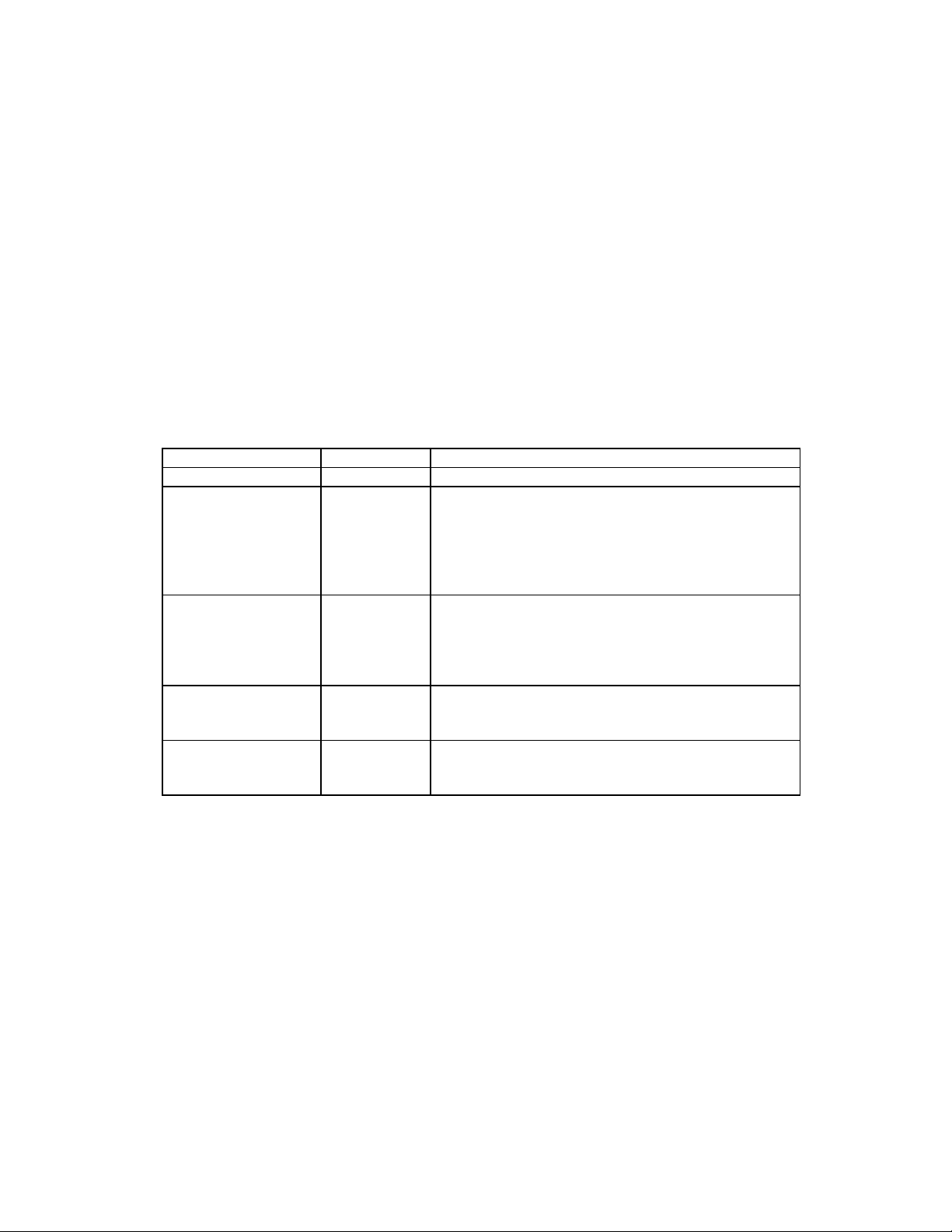
CONFIGURATIONS
The standard configurations of the Slim Profile Reader are as follows:
Part Number Description
21047013 Includes card guide; Track 1,2,3 head spring (21052086); No elect r onics
21047015 Includes card guide; Track 2 head spring
(21052019); - No electronics
21047016 Includes card guide; Track 1,2 head spring
(21052224); - No electronics
For convenient interface to the application electronics, the MagTek single-track IC (P/N
21006516) with associated components can be installed on the user’s own circuit board. Or, for
the 2-track and 3-track designs, the MagTek 3-track Delta ASIC (P/N 21006536) can be
incorporated into the target design.
SPECIFICATIONS
Specifications are as follows:
FLAMMABILITY
Flammability Meets UL94V-0
ENVIRONMENTAL
Operating Temperature -30 oC to 70 oC (-22 oF to +158 oF)
Operating Humidity 10% to 90% relative humidity
Life 300,000 passes Single Track
1,000,000 passes Multi-Track
PHYSICAL
Dimensions Length: 3.51" (89.2mm)
Height: 1.10" (27.9mm)
Width: 0.63" (16.0mm)
Head Cable Length
Connector See Section 2, Connectors
Single Track: 4.49" (114mm)
Dual Track: 2.60" (66mm)
Three track: 5.00” (127mm)
1
Page 8

Slim Profile Swipe Readers
REFERENCE DOCUMENTS
I/O Interface for TTL Swipe Readers, Technical Reference Manual, P/N 99875148
Triple Track ASIC With Shift-Out, Specifications, P/N 99875259
Page 9

SECTION 2. INSTALLATION
This section consists of installation of the Reader models.
MOUNTING
The mounting dimensions for Track 2 are shown in Figure 2-1; for Tracks 1 and 2 in Figure 2-2;
and for Tracks 1, 2, and 3 in Figure 2-3.
3
Page 10

Slim Profile Swipe Readers
4
Figure 2-1. Reader Mounting Dimensions, Track 2
Page 11

Section 2. Installation
Figure 2-2. Reader Mounting Dimensions, Tracks 1 and 2
5
Page 12

Slim Profile Swipe Readers
Figure 2-3. Reader Mounting Dimensions, Tracks 1, 2, and 3
Page 13

Section 2. Installation
CONNECTORS
Head connections for the three models are shown in the tables below.
Table 2-1. Head Connections for Track 2
Signal Color
Wires Only -
No Connector
HEAD CASE GND Black
READ HEAD TRACK 2 White
READ HEAD TRACK 2 Red
Table 2-2. Head Connections for Tracks 1 and 2
Connector for Dual Track, 5 Pin
Pin Number Signal Color
1 HEAD CASE (GND) Black
Molex 51021-0500
1.25 mm Contact Spacing
Mates with Headers 53398-0590,
53261-0590, 53047-0510, 53048-0510
2 READ HEAD TK 1 White
3 READ HEAD TK 1 Yellow
4 READ HEAD TK 2 Red
5 READ HEAD TK 2 Green
Table 2-3. Head Connections for Tracks 1, 2 and 3
Connector for Dual Track, 7 Pin
Molex 51021-0700
1.25 mm Contact Spacing
Mates with Headers 53398-0790,
53261-0790, 53047-0710, 53048-0710
Pin Number Signal Color
1 HEAD CASE (GND) Black
2 READ HEAD TK 1 Red
3 READ HEAD TK 1 Red
4 READ HEAD TK 2 Green
5 READ HEAD TK 2 Green
6 READ HEAD TK 3 Yellow
7 READ HEAD TK 3 Yellow
7
Page 14

Slim Profile Swipe Readers
 Loading...