

Page 1

P-SERIES USB
INSERTION READE R
TECHNICAL REFERENCE MANUAL
Manual Part Number 99875201 Rev 13
SEPTEMBER 2009
REGISTERED TO ISO 9001:2000
1710 Apollo Court
Seal Beach, CA 90740
Phone: (562) 546-6400
FAX: (562) 546-6301
Technical Support: (651) 415-6800
www.magtek.com
Page 2

ii
Rev Number
Date
Notes
1
05 Oct 01
Initial Release
2
19 Oct 01
Sec 4: Polling Interval Property, changed default value from 1
to 2
3
13 Nov 01
Sect 1: Changed operating temp spec to 0o to 65 o C (32 o to
149 o F)
4
12 Dec 02
Section 4, Command Number: Corrected GET and SET
PROPERTY descriptions
5
28 Jan 03
Changed copyright symbol so pdf copies would print on all
printers
6
03 Jun 03
Front Matter: added ISO line to logo, changed Tech Support
phone number, added new warranty statement
7
16 Jul 03
Sec 4: In the paragraph beginning “This device is powered…”
changed Product ID from 0x0002 to 0x0003
8
8 May 06
Removed reference to CDL; added support brackets
9
27 Mar 07
Updated FCC statement
10
14 Dec 07
Added 3-track reader (21065148); removed description of
mounting brackets
11
30 Jan 08
Added keyboard emulation feature.
12
22 June 09
Added 21065151; upd ated Limited Warranty and Agency
approvals
13
19 Sept 09
Replaced mounting bracket kit (21065811) w ith ne w k it
(21064519)
Copyright© 2001-2009
MagTek®, Inc.
Printed in the United States of America
Information in this document is subject to change without notice. No part of this document may
be reproduced or transmitted in any form or by any means, electronic or mechanical, for any
purpose, without the express written permission of MagTek, Inc.
MagTek is a registered trademark of MagTek, Inc.
USB (Universal Serial Bus) Specification is Copyright© 1998 by Compaq Computer
Corporation, Intel Corporation, Microsoft Corporation, NEC Corporation.
REVISIONS
Page 3

Limited Warranty
MagTek warrants that the products sold pursuant to this Agreement will perform in accordance with MagTek’s
published specifications. This warranty shall be provided only for a period of one year from the date of the
shipment of the product from MagTek (the “Warranty Period”). This warranty shall apply only to the “Buyer”
(the original purchaser, unless that entity resells the product as authorized by MagTek, in which event this
warranty shall apply only to the first repurchaser).
During the Warranty Period, should this product fail to conform to MagTek’s specifications, MagTek will, at its
option, repair or replace this product at no additional charge except as set forth below. Repair parts and
replacement products will be furnished on an exchange basis and will be either reconditioned or new. All replaced
parts and products become the property of MagTek. This limited warranty does not include service to repair
damage to the product resulting from accident, disaster, unreasonable use, misuse, abuse, negligence, or
modification of the product not authorized by MagTek. MagTek reserves the right to examine the alleged
defective goods to determine whether the warranty is applicable.
Without limiting the generality of the foregoing, MagTek specifically disclaims any liability or warranty for
goods resold in other than MagTek’s original packages, and for goods modified, altered, or treated without
authorization by MagTek.
Service may be obtained by delivering the product during the warranty period to MagTek (1710 Apollo Court,
Seal Beach, CA 90740). If this product is delivered by mail or by an equivalent shipping carrier, the customer
agrees to insure the product or assume the risk of loss or damage in transit, to prepay shipping charges to the
warranty service location, and to use the original shipping container or equivalent. MagTek will return the
product, prepaid, via a three (3) day shipping service. A Return Material Authorization (“RMA”) number must
accompany all returns. Buyers may obtain an RMA number by contacting Technical Support at (888) 624-8350.
EACH BUYER UNDERSTANDS THAT THIS MAGTEK PRODUCT IS
OFFERED AS IS.
MAGTEK MAKES NO OTHER WARRANTY , EXPRESS OR
IMPLIED, AND MAGTEK DISCLAIMS ANY WARRANTY OF ANY OTHER
KIND, INCLUDING ANY WARRANTY OF MERCHANTABILITY OR FITNESS
FOR A PARTICULAR PURPOSE.
IF THIS PRODUCT DOES NOT CONFORM TO MAGTEK’S SPECIFICATIONS, THE SOLE REMEDY
SHALL BE REPAIR OR REPLACEMENT AS PROVIDED ABOVE. MAGTEK’S LIABILITY, IF ANY,
SHALL IN NO EVENT EXCEED THE TOTAL AMOUNT PAID TO MAGTEK UNDER THIS
AGREEMENT. IN NO EVENT WILL MAGTEK BE LIABLE TO THE BUYER FOR ANY DAMAGES,
INCLUDING ANY LOST PROFITS, LOST SAVINGS, OR OTHER INCIDENTAL OR CONSEQUENTIAL
DAMAGES ARISING OUT OF THE USE OF, OR INABILITY TO USE, SUCH PRODUCT, EVEN IF
MAGTEK HAS BEEN ADVISED OF THE POSSIBILITY OF SUCH DAMAGES, OR FOR ANY CLAIM BY
ANY OTHER PARTY.
LIMITATION ON LIABILITY
EXCEPT AS PROVIDED IN THE SECTIONS RELATING TO MAGTEK’S LIMITED WARRANTY,
MAGTEK’S LIABILITY UNDER THIS AGREEMENT IS LIMITED TO THE CONTRACT PRICE OF THIS
PRODUCT.
MAGTEK MAKES NO OTHER WARRANTIES WITH RESPECT TO THE PRODUCT, EXPRESSED OR
IMPLIED, EXCEPT AS MAY BE STATED IN THIS AGREEMENT, AND MAGTEK DISCLAIMS ANY
IMPLIED WARRANTY, INCLUDING WITHOUT LIMITATION ANY IMPLIED WARRANTY OF
MERCHANTABILITY OR FITNESS FOR A PARTICULAR PURPOSE.
MAGTEK SHALL NOT BE LIABLE FOR CONTINGENT, INCIDENTAL, OR CONSEQUENTIAL
DAMAGES TO PERSONS OR PROPERTY. MAGTEK FURTHER LIMITS ITS LIABILITY OF ANY KIND
WITH RESPECT TO THE PRODUCT, INCLUDING ANY NEGLIGENCE ON ITS PART, TO THE
CONTRACT PRICE FOR THE GOODS.
MAGTEK’S SOLE LIABILITY AND BUYER’S EXCLUSIVE REMEDIES ARE STATED IN THIS SECTION
AND IN THE SECTION RELATING TO MAGTEK’S LIMITED WARRANTY.
iii
Page 4

iv
FCC WARNING STATEMENT
This equipment has been tested and was found to comply with the limits for a Class B digital device pursuant to
Part 15 of FCC Rules. These limits are designed to provide reasonable protection against harmful interference
when the equipment is operated in a residential environment. This equipment generates, uses, and can radiate
radio frequency energy and, if not installed and used in accordance with the instruction manual, may cause
harmful interference with radio communications. However, there is no guarantee that interference will not occur
in a particular installation.
FCC COMPLIANCE STATEMENT
This device complies with Part 15 of the FCC Rules. Operation of this device is subject to the following two
conditions: (1) this device may not cause harmful interference, and (2) this device must accept any interference
received, including interference that may cause undesired operation.
CANADIAN DOC STATEMENT
This digital apparatus does not exceed the Class B limits for radio noise from digital apparatus set out in the
Radio Interference Regulations of the Canadian Department of Communications.
Le présent appareil numérique n’émet pas de bruits radioélectriques dépassant les limites applicables aux
appareils numériques de la classe B prescrites dans le Réglement sur le brouillage radioélectrique édicté par le
ministère des Communications du Canada.
This Class B digital apparatus complies with Canadian ICES-003.
Cet appareil numériqué de la classe B est conformé à la norme NMB-003 du Canada.
CE STANDARDS
Testing for compliance with CE requirements was performed by an independent laboratory. The unit under test
was found compliant with s tandards established for Class B devices.
UL/CSA
This product is recognized per Underwriter Laboratories and Canadian Underwriter Laboratories 1950.
RoHS STATEMENT
When ordered as RoHS compliant, this product meets the Electrical and Electronic Equipment (EEE) Reduction
of Hazardous Substances (RoHS) European Directive 2002/95/EC. The marking is clearly recognizable, either as
written words like “Pb-free”, “lead-free”, or as another clear symbol ( ).
Page 5

TABLE OF CONTENTS
SECTION 1. FEATURES AND SPECIFICATIONS .................................................................................... 1
FEATURES ............................................................................................................................................... 2
CONFIGURATIONS ................................................................................................................................. 2
ACCESSORIES ........................................................................................................................................ 3
REFERENCE DOCUMENTS ................................................................................................................... 3
SPECIFICATIONS .................................................................................................................................... 4
SECTION 2. INSTALLATION ...................................................................................................................... 5
USB CONNECTION ................................................................................................................................. 5
WINDOWS PLUG AND PLAY S E TUP ..................................................................................................... 6
MOUNTING .............................................................................................................................................. 7
OPTIONAL MOUNTING BRACKET ......................................................................................................... 7
SECTION 3. OPERATION ........................................................................................................................... 9
SECTION 4. USB COMMUNICATIONS (HID) .......................................................................................... 11
HID USAGES .......................................................................................................................................... 12
REPORT DESCRIPTOR ........................................................................................................................ 13
CARD DATA ........................................................................................................................................... 13
TRACK 1 DECODE STATUS ................................................................................................................. 14
TRACK 2 DECODE STATUS ................................................................................................................. 14
TRACK 3 DECODE STATUS ................................................................................................................. 14
TRACK 1 DATA LENGTH ...................................................................................................................... 15
TRACK 2 DATA LENGTH ...................................................................................................................... 15
TRACK 3 DATA LENGTH ...................................................................................................................... 15
CARD ENCODE TYPE ........................................................................................................................... 15
TRACK DATA ......................................................................................................................................... 16
TRACK 1 DATA ...................................................................................................................................... 16
TRACK 2 DATA ...................................................................................................................................... 16
TRACK 3 DATA ...................................................................................................................................... 16
CARD STATUS....................................................................................................................................... 16
COMMANDS ........................................................................................................................................... 16
COMMAND NUMBER ............................................................................................................................ 17
DATA LENGTH ....................................................................................................................................... 17
DATA ...................................................................................................................................................... 17
RESULT CODE ...................................................................................................................................... 17
GET AND SET PROPERTY COMMANDS ............................................................................................ 18
SOFTWARE ID PROPERTY .................................................................................................................. 19
SERIAL NUM PROPERTY ..................................................................................................................... 19
POLLING INTERV AL PR OPERTY ......................................................................................................... 20
MSR DIRECTION PROPERTY .............................................................................................................. 21
CARD INSERTED PROPERTY.............................................................................................................. 22
MAX PACKET SIZE PROPERTY ........................................................................................................... 22
INTERFACE TYPE PROPERTY ............................................................................................................ 23
TRACK ID ENABLE PRO P ERTY ........................................................................................................... 24
RESET DEVICE COMMAND ................................................................................................................. 25
SECTION 5. USB COMMUNICATIONS (KB) ........................................................................................... 27
HOST APPLICATIONS ........................................................................................................................... 27
CARD DATA ........................................................................................................................................... 28
PROGRAMMABLE CONFIGURATION OPTIONS ................................................................................ 29
LOW LEVEL COMMUNICATIONS ......................................................................................................... 29
HID USAGES .......................................................................................................................................... 30
REPORT DESCRIPTOR ........................................................................................................................ 31
COMMANDS ........................................................................................................................................... 32
v
Page 6

vi
COMMAND NUMBER ............................................................................................................................ 32
DATA LENGTH ....................................................................................................................................... 32
DATA ...................................................................................................................................................... 32
RESULT CODE ...................................................................................................................................... 33
GET AND SET PROPERTY COMMANDS ............................................................................................ 33
SOFTWARE ID PROPERTY .................................................................................................................. 35
SERIAL NUM PROPERTY ..................................................................................................................... 35
POLLING INTERV AL PR OPERTY ......................................................................................................... 36
TRACK ID ENBLE PROPERTY ............................................................................................................. 37
TRACK DATA SEND FLAGS PROPERTY ............................................................................................ 38
TERMINATION CHAR PROPERTY ....................................................................................................... 39
SS_TK2_7BITS PROPERTY .................................................................................................................. 39
SS_TK3_ISO_ABA PROPERTY ............................................................................................................ 40
SS_TK3_AAMVA PROPERTY ............................................................................................................... 40
SS_TK3_7BITS PROPERTY .................................................................................................................. 40
PRE CARD CHAR PROPERTY ............................................................................................................. 41
POST CARD CHAR PROPERTY ........................................................................................................... 41
PRE TK CHAR PROPERTY ................................................................................................................... 41
POST TK CHAR PROPERTY ................................................................................................................ 42
ASCII TO KEYPRESS CONVERSION TYPE PROPERTY ................................................................... 42
INTERFACE TYPE PROPERTY ............................................................................................................ 43
ACTIVE KEYMAP PROPERTY .............................................................................................................. 44
PRE CARD STRING PROPERTY .......................................................................................................... 45
POST CARD STRING PROPERTY ....................................................................................................... 46
SS_TK1_ISO_ABA PROPERTY ............................................................................................................ 46
SS_TK2_ISO_ABA PROPERTY ............................................................................................................ 47
ES PROPERTY ...................................................................................................................................... 47
MSR DIRECTION PROPERTY .............................................................................................................. 48
CARD INSERTED PROPERTY.............................................................................................................. 49
SENSOR BLOCKED CHAR ................................................................................................................... 49
SENSOR UNBLOCKED CHAR .............................................................................................................. 50
ES_TK1 PROPERTY .............................................................................................................................. 51
ES_TK2 PROPERTY .............................................................................................................................. 51
ES_TK3 PROPERTY .............................................................................................................................. 51
RESET DEVICE COMMAND ................................................................................................................. 52
GET KEYMAP ITEM COMMAND ........................................................................................................... 52
SET KEYMAP ITEM COMMAND ........................................................................................................... 54
SAVE CUSTOM KEYMAP COMMAND ................................................................................................. 56
SECTION 6. DEMO PROGRAM ............................................................................................................... 57
INSTALLATION ...................................................................................................................................... 57
OPERATION ........................................................................................................................................... 57
SOURCE CODE ..................................................................................................................................... 58
APPENDIX A. USAGE ID DEFINITIONS .................................................................................................. 59
KEYBOARD/KEYPAD PAGE (0X07) ..................................................................................................... 59
APPENDIX B. MODIFIER BYTE DEFINITIONS ....................................................................................... 67
APPENDIX C. MECHANICAL DRAWING FOR MOUNTING ................................................................... 68
Page 7

vii
FIGURES & TABLES
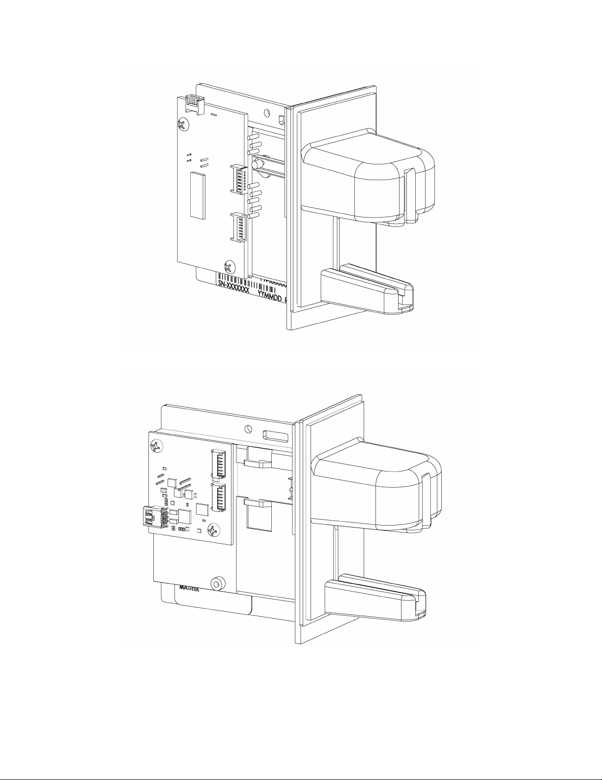
Figure 1-1. P-Series USB Insertion Reader – 2-Track ---------------------------------------------------------------- viii
Figure 1-2. P-Series USB Insertion Reader – 3-Track ---------------------------------------------------------------- viii
Table 1-2. Specifications -------------------------------------------------------------------------------------------------------- 4
Figure 2-1. Cabling for 21065128 --------------------------------------------------------------------------------------------- 5
Table 2-1. 5-Pin Connector (J1) ----------------------------------------------------------------------------------------------- 5
Figure 2-2. Cabling for 21065148 and 21065151 ------------------------------------------------------------------------- 6
Table 2-2. 5-Pin USB Mini-B Connector (J1) ------------------------------------------------------------------------------ 6
Figure 2-3. MagTek Bezel Mounting Posit ion ------------------------------------------------------------------------------ 7
Table A-1. Keyboard/Keypad ------------------------------------------------------------------------------------------------ 59
Table B-1. Modifier Byte ------------------------------------------------------------------------------------------------------ 67
Figure C-1. Dimensions for Mounting -------------------------------------------------------------------------------------- 68
Page 8
viii
Figure 1-1. P-Series USB Insertion Reader – 2-Track
Figure 1-2. P-Series USB Insertion Reader – 3-Track
Page 9

1
SECTION 1. FEATURES AND SPECIFICATIONS
The P-Series USB (Universal Serial Bus) Insertion Reader is a compact magnetic stripe card
reader, which conforms to ISO standards. The Reader is compatible with the PC series of
personal computers or any device with a USB interface. The reader can have single or dual head
configurations. The dual head configuration can read a card with the magnetic stripe orientated
in two directions. The single head configuration can read a card with the magnetic stripe
orientated in one direction. A card is read by inserting it into and/or removing it out of the card
slot when the card is oriented such that the card’s magnetic stripe contacts a read head.
The two-track version of the reader has circuitry that automatically ensures that the ISO
magnetic stripe is read in the case where a dual-stripe JIS (Japanese) credit card is inserted on the
dual head unit (the JIS stripe is ignored). On the three-track models, 2-sided cards cannot be
read.
The reader conforms to the USB Human Interface Device (HID) Class specification Version 1.1.
This allows host applications designed for most versions of Windows to easily communicate to
the reader using standard Windows API calls that communicate to the reader through the HID
driver that comes with Windows.
The Reader can be operated in two different modes:
• HID (herein referred to as “HID mode”) and
• HID with Keyboard Emulation (herein referred to as “KB mode”)
Note that only reader part number 21065148 and 21065151 with firmware version
21042817C01 or newer supports both modes. The other readers only support HID mode.
When operating in the HID mode, this device will not use keyboard emulation. It behaves like a
vendor defined HID device so that a direct communication path can be established between the
host application and the device, without interference from other HID devices.
When configured for the Keyboard Emulation (KB) mode, the Reader emulates a USB HID
United States keyboard or, optionally, any international keyboard using ALT ASCII code keypad
key combinations or customizable key maps. This allows host applications designed to acquire
card data from keyboard input to seamlessly acquire the card data from the USB swipe reader.
When in Keyboard Emulation mode, if another keyboard is connected to the same host as this device and a
key is pressed on the other keyboard while this device is transmitting, then the data transmitted by this device
may get corrupted.
Caution
A demo program, written in Visual Basic, with its source code is available. It exercises the
reader using the standard Windows API.
Page 10

P-Series USB Insertion Reader
2
Interface
Type
21065128
Dual head
1,2
HID
Molex
21065148
Dual head
1,2,3
HID
USB mini-B
21065151
Dual head
1,2,3
KB
USB mini-B
FEATURES
Major features of the Insert Reader are as follows:
• Powered through the USB – no external power supply required
• Hardware Compatible with PC or any computer or terminal with a USB interface
• JIS Discrimination circuitry - automatically detects if a dual-stripe JIS (Japanese Industrial
Standard) card is inserted and auto-routes the ISO data signals to the microcontroller. This
ensures that dual-head features still work for Japanese card holders. (Only supported on the
2-track model.)
• Mag-Stripe reading during insertion and/or removal of card – for reliable card reading
• Reads encoded data that meets ANSI/ISO/AAMVA standards and others such as ISO track 1
format on track 2
• Reads up to three tracks of card data
• Error reduction for withdrawal reads by using good insert read data
• Compatible with USB specification Revision 1.1
• Compatible with HID specification Version 1.1
• Can use standard Windows HID driver for communications; no third party device driver is
required
• Programmable USB serial number descriptor
• Programmable USB Interrupt In Endpoint polling interval
• Programmable read direction. (insert, withdrawal or both)
• Non-volatile flash EEPROM memory for property storage
• Optional 6-foot Black or Pearl White cable
• Sealed Chassis design - provides superior protection from moisture
• Isolated PCB - isolates electronics from debris and liquids
• AGC (Automatic Gain Control) in MagTek’s latest read IC - enhances read performance
with less susceptibility to RF interference
• Beam-mounted Read-heads - improves card tracking capabilities
• Ruggedized Chassis and Bezel Material - improves temperature and impact performance
CONFIGURATIONS
The available configurations are as follows:
Part Number Head Configuration Tracks
Connector
Page 11

Section 1. Features and Specifications
3
Part Number
Description
16051430
USB A to USB Mini-B, Pearl White, 6 ft.
21041494
5-Pin Molex Cable, Pearl White, 6 ft.
21041495
5-Pin Molex Cable, Black, 6 ft.
21042806
USB MSR Demo Program with Source Code (Diskette)
21064519
Angle Bracket Mounting Kit
99510026
USB MSR Demo Program with Source Code (WEB)
ACCESSORIES
The accessories are as follows:
REFERENCE DOCUMENTS
Axelson, Jan. USB Complete, Everything You Need to Develop Custom USB Peripherals, 1999.
Lakeview Research, 2209 Winnebago St., Madison WI 53704, 396pp., http://www.lvr.com.
USB Human Interface Device (HID) Class Specification Version 1.1.
USB (Universal Serial Bus) Specification, Version 1.1, Copyright 1998 by Compaq Computer
Corporation, Intel Corporation, Microsoft Corporation, NEC Corporation.
USB Implementers Forum, Inc., www.usb.org.
The P-Series USB Insertion Reader will read cards that meet the standards defined by ISO
(International Standards Organization):
ISO 7811 Identification Cards - Mag-stripe Cards, Tracks 1-3
ISO 7810 Identification Cards - Physical Specifications (ID-1 Cards)
Page 12

P-Series USB Insertion Reader
4
Reference Standards
ISO 7810 and ISO 7811, AAMVA & JISB9561*
Power Input
5V from USB port
Recording Method
Two-frequency coherent phase (F2F)
Message Format
ASCII
Card Speed
3 to 50 IPS
Head Life
1,000,000 passes (500,000 insert cycles)
ELECTRICAL
Current
Suspend Mode
300 uA
MECHANICAL
Weight
3.74 oz. (106.03 g)
Dimensions
See Appendix A
Cable length
Optional
ENVIRONMENTAL
Temperature
Operating
-40 oF to 185 oF (-40 oC to 85 oC)
Storage
-40 oF to 185 oF (-40 oC to 85 oC)
Humidity
Operating
10% to 90% noncondensing
Storage
10% to 90% noncondensing
SPECIFICATIONS
Table 1-2 lists the specifications for the USB P-Series Insert Reader.
Table 1-2. Specifications
Normal Mode
* ISO (International Standards Organization), AAMVA (American Association of Motor Vehicle
Administrators) and JIS B9561 (Japanese Industrial Standard).
30 mA
Page 13

5
Pin Number
Signal
Cable Color
1
VCC
Red
2
- Data
White
3
+Data
Green
4
Ground
Black
5
Shield Ground
Black
SECTION 2. INSTALLATION
This section describes the cable connection, the Windows Plug and Play Setup, and the physical
mounting of the unit.
USB CONNECTION
Connect the optional USB cable to a USB port on the host. The readers and pin numbers for the
cable connectors are shown in Figure 2-1 and Figure 2-2. The optional MagTek or user-supplied
cable is attached to J1 on either model.
Figure 2-1. Cabling for 21065128
The 5-pin connections (on J1) between the Reader and the USB connector shown in the
illustration are listed in Table 2-2.
Table 2-1. 5-Pin Connector (J1)
Page 14

P-Series USB Insertion Reader
6
Pin Number
Signal
Cable Color
1
V
BUS
Red
2
- Data
White
3
+Data
Green
4
n/c
- -
5
Ground
Black
Figure 2-2. Cabling for 21065148 and 21065151
The 5-pin USB mini-B connector pin numbers and signal descriptions shown in the illustration
are listed in Table 2-1.
Table 2-2. 5-Pin USB Mini-B Connector (J1)
WINDOWS PLUG AND PLAY SETUP
On hosts with the Windows operating system, the first time the reader is plugged into a specific
USB port, Windows will pop up a dialog box, which will guide you through the process of
installing a device driver for the reader. After this process is completed once, Windows will no
longer request this process as long as the reader is plugged into the same USB port. The device
driver that Windows will install for this reader is the driver used for HID devices and it is part of
the Windows operating system. When the dialog box pops up, follow the instructions given to
you in the dialog box. Sometimes Windows will find all the files it needs on its own without
giving you any prompts. Other times Windows will need to know the location of the files it
needs. If Windows prompts you for the file locations, insert the CD that was used to install
Windows on your PC and point Windows to the root directory of the CD. Windows should find
all the files it needs there.
Page 15

Section 2. Installation
7
MOUNTING
The standard orientation of the Reader is with the larger guide up as shown in Figure 2-3. The
position shown offers the best protection for the heads from moisture, dust, or foreign particles.
In both models, connector J3 is wired to the head that is on the same side as the PCB. Connector
J2 is wired to the head that is opposite the PCB. The magnetic stripe must be inserted in the
Large Guide but may be facing in either direction.
Figure 2-3. MagTek Bezel Mounting Position
OPTIONAL MOUNTING BRACKET
In applications where moisture-intrusion is a concern, it is recommended that the reader be
mounted with a 4
o
- 5o downward angle with respect to the horizontal plane. This will allow
gravity to drain away any excess moisture that may have entered into the Card Reader slot.
For more information about the mounting bracket kit (21064519) that can be used to tip the
reader forward, contact your MagTek salesperson.
Page 16

P-Series USB Insertion Reader
8
Page 17

9
SECTION 3. OPERATION
A card may be read by inserting it into the Reader slot or removing it from the Reader slot. The
direction of the read that is sent to the host is controlled by the MSR_DIRECTION property,
which is described in the next section. The magnetic stripe must face toward a read head during
the swipe. Once the card is swiped, the reader will attempt to decode the data and then send the
results to the host via a USB HID input report or, if in Keyboard Emulation mode, as if the data
was being typed on a keyboard. After the results are sent to the host, the reader will be ready to
read the next swipe. To help reduce read errors, if a good read occurs when the card is inserted
and a bad read occurs when the card is removed, then the read data for the card insert will be sent
to the host when the card is removed instead of the bad read data from the removal.
Page 18

P-Series USB Insertion Reader
10
Page 19

11
SECTION 4. USB COMMUNICATIONS (HID)
The Reader can be operated in two different modes:
• HID (herein referred to as “HID mode”) and
• HID with Keyboard Emulation (herein referred to as “KB mode”)
Note that only readers 21065148 and 21065151 with firmware version 21042817C01 or newer
support both modes. The other readers only support HID mode.
When operating in the HID mode, this device will not use keyboard emulation. It behaves like a
vendor defined HID device so that a direct communication path can be established between the
host application and the device, without interference from other HID devices.
When configured for the Keyboard Emulation (KB) mode, the Reader emulates a USB HID
United States keyboard or, optionally, any international keyboard using ALT ASCII code keypad
key combinations or customizable key maps. This allows host applications designed to acquire
card data from keyboard input to seamlessly acquire the card data from the USB swipe reader.
This section only describes USB communications when the device is in the HID mode. See the
USB communications (KB) section for a description of USB communication when the device is
in the KB mode. (Refer to
This device conforms to the USB specification revision 1.1. This device also conforms with the
Human Interface Device (HID) class specification version 1.1. The device communicates to the
host as a vendor defined HID device. The details about how the card data and commands are
structured into HID reports follow later in this section. The latest versions of the Windows
operating systems come with a standard Windows USB HID driver. Windows applications that
communicate to this device can be easily developed. These applications can communicate to the
device using standard windows API calls that communicate to the device using the standard
Windows USB HID driver. These applications can be easily developed using compilers such as
Microsoft’s Visual Basic or Visual C++. A demonstration program and its source code, written
in Visual Basic, that communicates with this device is available. This demo program can be
used to test the device and it can be used as a guide for developing other applications. More
details about the demo program follow later in this document.
It is recommended that application software developers become familiar with the HID
specification and the USB specification before attempting to communicate with this device. This
document assumes that the reader is familiar with these specifications. These specifications can
be downloaded free from www.usb.org.
This is a full speed USB device. This device has a number of programmable configuration
properties. These properties are stored in non-volatile memory. These properties can be
configured at the factory or by the end user. More details about these properties can be found
later in this document in the command section.
Interface_Type Property for information on how to change modes.)
Page 20

P-Series USB Insertion Reader
12
Usage ID
(Hex)
Usage Name
Usage
Type
Report
Type
1
Decoding reader device
Collection
None
20
Track 1 decode status
Data
Input
21
Track 2 decode status
Data
Input
22
Track 3 decode status
Data
Input
28
Track 1 data length
Data
Input
29
Track 2 data length
Data
Input
2A
Track 3 data length
Data
Input
30
Track 1 data
Data
Input
31
Track 2 data
Data
Input
32
Track 3 data
Data
Input
38
Card encode type
Data
Input
39
Card status
Data
Input
20
Command message
Data
Feature
The device will go into suspend mode when directed to do so by the host. The device will
wakeup from suspend mode when directed to do so by the host. The device does not support
remote wakeup.
This device is powered from the USB bus. Its vendor ID is 0x0801 and its product ID is 0x0003.
HID USAGES
HID devices send data in reports. Elements of data in a report are identified by unique identifiers
called usages. The structure of the device’s reports and the device’s capabilities are reported to
the host in a report descriptor. The host usually gets the report descriptor only once, right after
the device is plugged in. The report descriptor usages identify the devices capabilities and report
structures. For example, a device could be identified as a keyboard by analyzing the device’s
report descriptor. Usages are four byte integers. The most significant two bytes are called the
usage page and the least significant two bytes are called usage IDs. Usages that are related can
share a common usage page. Usages can be standardized or they can be vendor defined.
Standardized usages such as usages for mice and keyboards can be found in the HID Usage
Tables document and can be downloaded free at www.usb.org. Vendor defined usages must
have a usage page in the range 0xff00 – 0xffff. All usages for this device use vendor defined
magnetic stripe reader usage page 0xff00. The usage IDs for this device are defined in the
following table. The usage types are also listed. These usage types are defined in the HID
Usage Tables document.
Magnetic Stripe Reader usage page 0xff00:
Page 21

Section 4. USB Communications (HID)
13
Item
Value(Hex)
Usage Page (Magnetic Stripe Reader)
06 00 FF
Usage (Decoding reader device)
09 01
Collection (Application)
A1 01
Logical Minimum (0)
15 00
Logical Maximum (255)
26 FF 00
Report Size (8)
75 08
Usage (Track 1 decode status)
09 20
Usage (Track 2 decode status)
09 21
Usage (Track 3 decode status)
09 22
Usage (Track 1 data length)
09 28
Usage (Track 2 data length)
09 29
Usage (Track 3 data length)
09 2A
Usage (Card encode type)
09 38
Report Count (7)
95 07
Input (Data, Variable, Absolute, Bit Field)
81 02
Usage (Track 1 data)
09 30
Report Count (110)
95 6E
Input (Data, Variable, Absolute, Buffered Bytes)
82 02 01
Usage (Track 2 data)
09 31
Report Count (110)
95 6E
Input (Data, Variable, Absolute, Buffered Bytes)
82 02 01
Usage (Track 3 data)
09 32
Report Count (110)
95 6E
Input (Data, Variable, Absolute, Buffered Bytes)
82 02 01
Usage (Card Status)
09 39
Report Count (1)
95 01
Input (Data, Variable, Absolute, Bit Field)
81 02
Usage (Command message)
09 20
Report Count (24)
95 18
Feature (Data, Variable, Absolute, Buffered
Bytes)
B2 02 01
End Collection
C0
REPORT DESCRIPTOR
The HID report descriptor is structured as follows:
CARD DATA
Card data is only sent to the host on the Interrupt In pipe using an Input Report. The device will
send only one Input Report per card swipe. The MSR direction property, defined later in this
section, determines the direction of the card swipe that will generate an Input Report. This
property can be set to insert, withdrawal or both. If the host requests data from the device when
no data is available, the device will send a Nak to the host to indicate that it has nothing to send.
When a card is swiped, the Input Report will be sent even if the data is not decodable. The
following table shows how the input report is structured.
Page 22

P-Series USB Insertion Reader
14
Offset
Usage Name
0
Track 1 decode status
1
Track 2 decode status
3
Track 1 data length
5
Track 3 data length
6
Card encode type
7 – 116
Track 1 data
227 - 336
Track 3 data
Bits
7-1 0 Value
Reserved
Error
Bits
7-1 0 Value
Reserved
Error
Bits
7-1 0 Value
Reserved
Error
2 Track 3 decode status
4 Track 2 data length
117 – 226 Track 2 data
337 Card Status
TRACK 1 DECODE STATUS
This is a one-byte value, which indicates the status of decoding track 1. Bit position zero
indicates there was an error decoding track 1 if the bit is set to 1. If it is zero, then no error
occurred. If a track has data on it that is not noise, and it is not decodable, then a decode error is
indicated. If a decode error is indicated, the corresponding track data length value for the track
that has the error will be set to zero and no valid track data will be supplied.
TRACK 2 DECODE STATUS
This is a one-byte value, which indicates the status of decoding track 2. Bit position zero
indicates if there was an error decoding track 2 if this bit is set to one. If it is zero, then no error
occurred. If a track has data on it that is not noise, and it is not decodable, then a decode error is
indicated. If a decode error is indicated, the corresponding track data length value for the track
that has the error will be set to zero and no valid track data will be supplied.
TRACK 3 DECODE STATUS
This is a one-byte value, which indicates the status of decoding track 3. Bit position zero
indicates there was an error decoding track 3 if this bit is set to one. If it is zero, then no error
occurred. If a track has data on it that is not noise, and it is not decodable, then a decode error is
indicated. If a decode error is indicated, the corresponding track data length value for the track
that has the error will be set to zero and no valid track data will be supplied.
Page 23

Section 4. USB Communications (HID)
15
Value
Encode Type
Description
0
ISO/ABA
ISO/ABA encode format
1
AAMVA
AAMVA encode format
2
CADL
No longer supported
3
Blank
The card is blank
4
Other
The card has a non-standard encode format. For example, ISO/ABA
track 1 format on track 2.
5
Undetermined
The card encode type could not be determined because no tracks could
be decoded.
6
None
No decode has occurred. This type occurs if no magnetic stripe data
has been swiped so this value will never occur.
TRACK 1 DATA LENGTH
This one byte value indicates how many bytes of decoded card data are in the track 1 data field.
This value will be zero if there was no data on the track or if there was an error decoding the
track.
TRACK 2 DATA LENGTH
This one byte value indicates how many bytes of decoded card data are in the track 2 data field.
This value will be zero if there was no data on the track or if there was an error decoding the
track.
TRACK 3 DATA LENGTH
This one byte value indicates how many bytes of decoded card data are in the track 3 data field.
This value will be zero if there was no data on the track or if there was an error decoding the
track.
CARD ENCODE TYPE
This one byte value indicates the type of encoding that was found on the card. The following
table defines the possible values.
has been acquired since the data has been cleared or since the device
was powered on. This device only sends an Input report when a card
Page 24

P-Series USB Insertion Reader
16
Bits
7-1 0 Value
Reserved
Card Inserted
TRACK DATA
If decodable track data exits for a given track, it is located in the track data field that corresponds
to the track number. The length of each track data field is fixed at 110 bytes, but the length of
valid data in each field is determined by the track data length field that corresponds to the track
number. Track data located in positions greater that the track data length field indicates are
undefined and should be ignored. The HID specification requires that reports be fixed in size,
but the number of bytes encoded on a card may vary. Therefore, the Input Report always
contains the maximum amount of bytes that can be encoded on the card and the number of valid
bytes in each track is indicated by the track data length field. The track data is decoded and
converted to ASCII. The track data includes all data starting with the start sentinel and ending
with the end sentinel.
TRACK 1 DATA
This field contains the decoded track data for track 1.
TRACK 2 DATA
This field contains the decoded track data for track 2.
TRACK 3 DATA
This field contains the decoded track data for track 3.
CARD STATUS
This is a one-byte value, which indicates the card status. Bit position zero indicates that the card
was swiped in the insertion direction if it is set to one. If it is set to zero, then the card was
swiped in the withdrawal direction. All other bit positions are reserved.
COMMANDS
Most host applications do not need to send commands to the device. Most host applications only
need to obtain card data from the device as described previously in this section. This section of
the manual can be ignored by anyone who does not need to send commands to the device.
Command requests and responses are sent to and received from the device using feature reports.
Command requests are sent to the device using the HID class specific request Set_Report. The
response to a command is retrieved from the device using the HID class specific request
Get_Report. These requests are sent over the default control pipe. When a command request is
sent, the device will Nak the Status stage of the Set_Report request until the command is
completed. This insures that as soon as the Set_Report request is completed, the Get_Report
request can be sent to get the command response. The usage ID for the command message was
shown previously in the Usage Table.
Page 25

Section 4. USB Communications (HID)
17
Offset
Field Name
0
Command Number
1
Data Length
2 – 23
Data
Offset
Field Name
0
Result Code
1
Data Length
2 – 23
Data
Value
Command Number
Description
0
GET_PROPERTY
Gets a property from the device
1
SET_PROPERTY
Sets a property in the device
2
RESET_DEVICE
Resets the device
Value
Result Code
Description
0
SUCCESS
The command completed successfully.
1
FAILURE
The command failed.
parameter or command syntax error.
The following table shows how the feature report is structured for command requests:
The following table shows how the feature report is structured for command responses.
COMMAND NUMBER
This one byte field contains the value of the requested command number. The following table
lists all the existing commands.
DATA LENGTH
This one byte field contains the length of the valid data contained in the Data field.
DATA
This multi-byte field contains command data if any. Note that the length of this field is fixed at
22 bytes. Valid data should be placed in the field starting at offset 2. Any remaining data after
the valid data should be set to zero. This entire field must always be set even if there is no valid
data. The HID specification requires that Reports be fixed in length. Command data may vary
in length. Therefore, the Report should be filled with zeros after the valid data.
RESULT CODE
This one byte field contains the value of the result code. There are two types of result codes:
generic result codes and command specific result codes. Generic result codes always have the
most significant bit set to zero. Generic result codes have the same meaning for all commands
and can be used by any command. Command specific result codes always have the most
significant bit set to one. Command specific result codes are defined by the command that uses
them. The same code can have different meanings for different commands. Command specific
result codes are defined in the documentation for the command that uses them. Generic result
codes are defined in the following table.
2 BAD_PARAMETER The command failed due to a bad
Page 26

P-Series USB Insertion Reader
18
Data Offset
Value
0
Property ID
Data Offset
Value
0 – n
Property Value
Data Offset
Value
0
Property ID
1 – n
Property Value
Value
Property ID
Description
0
SOFTWARE_ID
The device’s software identifier
1
SERIAL_NUM
The device’s serial number
2
POLLING_INTERVAL
The interrupt pipe’s polling interval
3
MSR_DIRECTION
Magnetic stripe read direction
4
CARD_INSERTED
Card inserted indicator
5
MAX_PACKET_SIZE
The interrupt pipe’s packet size
16
INTERFACE_TYPE
Type of USB interface
27
TRACK_ID_ENABLE
Allows Tracks to be disabled
GET AND SET PROPERTY COMMANDS
The Get Property command gets a property from the device. The Get Property command
number is 0.
The Set Property command sets a property in the device. The Set Property command number
is 1.
The Get and Set Property command data fields for the requests and responses are structured as
follows:
Get Property Request Data:
Get Property Response Data:
Set Property Request Data:
Set Property Response Data:
None
The result codes for the Get and Set Property commands can be any of the codes list in the
generic result code table.
Property ID is a one-byte field that contains a value that identifies the property. The following
table lists all the current property ID values:
The Property Value is a multiple byte field that contains the value of the property. The number
of bytes in this field depends on the type of property and the length of the property. The
following table lists all of the property types and describes them.
Page 27

Section 4. USB Communications (HID)
19
Property Type
Description
Byte
This is a one byte value. The valid values depend on the property.
String
This is a multiple byte ASCII string. Its length can be zero to a
Cmd Num
Data Len
Prp ID
00
01
00
Result Code
Data Len
Prp Value
00
01
32 31 30 34 32 38 31 37 43 30 31
Cmd Num
Data Len
Prp ID
Prp Value
01
04
01
31 32 33
maximum length that depends on the property. The value and
length of the string does not include a terminating NUL character.
SOFTWARE ID PROPERTY
Property ID: 0
Property Type: String
Length: Fixed at 11 bytes
Get Property: Yes
Set Property: No
Description: This is an 11 byte read only property that identifies the software part
number and version for the device. The first 8 bytes represent the part number and the last 3
bytes represent the version. For example this string might be “21042817C01”. Examples
follow:
Example Get Software ID property Request (Hex):
Example Get Software ID property Response (Hex):
SERIAL NUM PROPERTY
Property ID: 1
Property Type: String
Length: 0 – 15 bytes
Get Property: Yes
Set Property: Yes
Default Value: The default value is no string with a length of zero.
Description: The value is an ASCII string that represents the device’s serial number.
This string can be 0 – 15 bytes long. This property is stored in nonvolatile EEPROM memory so it will not change when the unit is power
cycled. The value of this property, if any, will be sent to the host when the
host requests the USB string descriptor. When this property is changed,
the unit must be power cycled to have these changes take effect for the
USB descriptor. If a value other than the default value is desired, it can be
set by the factory upon request. Examples follow.
Example Set Serial Num property Request (Hex):
Page 28

P-Series USB Insertion Reader
20
Result Code
Data Len
Data
00
00
Cmd Num
Data Len
Prp ID
00
01
01
Result Code
Data Len
Prp Value
00
03
31 32 33
Cmd Num
Data Len
Prp ID
Prp Value
01
02
02
0A
Result Code
Data Len
Data
00
00
Cmd Num
Data Len
Prp ID
00
01
02
Example Set Serial Num property Response (Hex):
Example Get Serial Num property Request (Hex):
Example Get Serial Num property Response (Hex):
POLLING INTERVAL PROPERTY
Property ID: 2
Property Type: Byte
Length: 1 byte
Get Property: Yes
Set Property: Yes
Default Value: 2
Description: The value is a byte that represents the devices polling interval for the
Interrupt In Endpoint. The value can be set in the range of 1 – 255 and has
units of milliseconds. The polling interval tells the host how often to poll
the device for card data packets. For example, if the polling interval is set
to 10, the host will poll the device for card data packets every 10ms. This
property can be used to speed up or slow down the time it takes to send
card data to the host. The trade-off is that speeding up the card data
transfer rate increases the USB bus bandwidth used by the device, and
slowing down the card data transfer rate decreases the USB bus bandwidth
used by the device. This property is stored in non-volatile EEPROM
memory so it will not change when the unit is power cycled. The value of
this property will be sent to the host when the host requests the device’s
USB endpoint descriptor. When this property is changed, the unit must be
power cycled to have these changes take effect for the USB descriptor. If
a value other than the default value is desired, it can be set by the factory
upon request. Examples follow:
Example Set Polling Interval property Request (Hex):
Example Set Polling Interval property Response (Hex):
Example Get Polling Interval property Request (Hex):
Page 29

Section 4. USB Communications (HID)
21
Result Code
Data Len
Prp Value
00
01
0A
Cmd Num
Data Len
Prp ID
Prp Value
01
02
03
02
Result Code
Data Len
Data
00
00
Cmd Num
Data Len
Prp ID
00
01
03
Example Get Polling Interval property Response (Hex):
MSR DIRECTION PROPERTY
Property ID: 3
Property Type: Byte
Length: 1 byte
Get Property: Yes
Set Property: Yes
Default Value: 2 (Withdrawal)
Description: This value is a byte that represents the devices magnetic stripe read
direction. The device will generate a USB HID Input Report when a card
is swiped in the direction indicated by this property. The value can be set
to 1 for insert, 2 for withdrawal or 3 for both directions. If this property is
set to 3 (both) then it is strongly recommended that the devices
POLLING_INTERVAL property is set to 2ms or less and that the devices
MAX_PACKET_SIZE is set to 32 bytes or more so that the device can
keep up with the speed of swiping in both directions. If this is not done
then if a card is withdrawn quickly after inserting the card, the withdrawal
may have a read error because the read will not start until the device is
finished sending the USB HID Input Report to the host for the Insert read.
This property is stored in non-volatile EEPROM memory so it will not
change when the unit is power cycled. When this property is changed, the
unit must be power cycled to have these changes take effect. If a value
other than the default value is desired, it can be set by the factory upon
request.
Note that this reader reads better when a card is removed from it than
when a card is inserted into it.
Examples follow:
Example Set MSR Direction property Request (Hex):
Example Set MSR Direction property Response (Hex):
Example Get MSR Direction property Request (Hex):
Page 30

P-Series USB Insertion Reader
22
Result Code
Data Len
Prp Value
00
01
02
Cmd Num
Data Len
Prp ID
00
01
04
Result Code
Data Len
Prp Value
00
01
01
Example Get MSR Direction property Response (Hex):
CARD INSERTED PROPERTY
Property ID : 4
Property Type: Byte
Length: 1 byte
Get Property: Yes
Set Property: No
Default Value: None
Description: This value is used to determine if a card is fully inserted into the device.
If a card is fully inserted into the device this property will contain one. If not, the property will
contain zero. This property is intended to be used by hosts that want to check if a card is
currently inserted in the device during startup. This card inserted information is also contained
in the Card Status field of the Input report sent to the host during each card swipe. So there
should be no need to poll the host for this information on a continuing basis. Examples follow:
Example Get Card Inserted property Request (Hex):
Example Get Card Inserted property Response (Hex):
MAX PACKET SIZE PROPERTY
Property ID: 5
Property Type: Byte
Length: 1 byte
Get Property: Yes
Set Property: Yes
Default Value: 32
Description: The value is a byte that represents the devices maximum packet size for
the Interrupt In Endpoint. The value can be set in the range of 1 – 64 and has units of bytes. The
maximum packet size tells the host the maximum size of the Interrupt In Endpoint packets. For
example, if the maximum packet size is set to 32, the device will send HID reports in multiple
packets of 32 bytes each or less for the last packet of the report. This property can be used to
speed up or slow down the time it takes to send card data to the host. Larger packet sizes speed
up communications and smaller packet sizes slow down communications. The trade-off is that
speeding up the card data transfer rate increases the USB bus bandwidth used by the device, and
slowing down the card data transfer rate decreases the USB bus bandwidth used by the device.
This property is stored in non-volatile EEPROM memory so it will not change when the unit is
power cycled. The value of this property will be sent to the host when the host requests the
device’s USB endpoint descriptor. When this property is changed, the unit must be power
Page 31

Section 4. USB Communications (HID)
23
Cmd Num
Data Len
Prp ID
Prp Value
01
02
05
20
Result Code
Data Len
Data
00
00
Cmd Num
Data Len
Prp ID
00
01
05
Result Code
Data Len
Prp Value
00
01
20
Cmd Num
Data Len
Prp ID
Prp Value
01
02
10
01
Result Code
Data Len
Data
00
00
cycled to have these changes take effect for the USB descriptor. If a value other than the default
value is desired, it can be set by the factory upon request. Examples follow:
Example Set Max Packet Size property Request (Hex):
Example Set Max Packet Size property Response (Hex):
Example Get Max Packet Size property Request (Hex):
Example Get Max Packet Size property Response (Hex):
INTERFACE TYPE PROPERTY
Property ID: 16 (0x10)
Property Type: Byte
Length: 1 byte
Get Property: Yes
Set Property: Yes
Default Value: 0 (HID)
Description: The value is a byte that represents the devices interface type. The value can
be set to 0 for the HID interface or to 1 for the keyboard emulation interface.
When the value is set to 0 (HID) the device will behave as described in the
USB communications (HID) section of the manual. When the value is set to 1
(keyboard emulation) the device will behave as described in the USB
communications (KB) section of the manual. This property should be the first
property changed because it affects which other properties are available.
After this property is changed, the device should be power cycled before
changing any other properties.
This property is stored in non-volatile memory, so it will persist when the unit
is power cycled. When this property is changed, the unit must be reset (see
Command Number 2) or power cycled to have these changes take effect.
Example Set Interface Type property Request (Hex):
Example Set Interface Type property Response (Hex):
Page 32

P-Series USB Insertion Reader
24
Cmd Num
Data Len
Prp ID
00
01
10
Result Code
Data Len
Prp Value
00
01
00
Cmd Num
Data Len
Prp ID
Prp Value
01
02
1B
95
Result Code
Data Len
Data
00
00
Cmd Num
Data Len
Prp ID
00
01
1B
Result Code
Data Len
Prp Value
00
01
95
Example Get Interface Type property Request (Hex):
Example Get Interface Type property Response (Hex):
TRACK ID ENABLE PROPERTY
Property ID: 27 (0x1B)
Property Type: Byte
Length: 1 byte
Get Property: Yes
Set Property: Yes
Default Value: 0x95
Description: This property is defined as follows:
id 0 T3 T3 T2 T2 T1 T1
Id 0 – Decodes standard ISO/ABA cards only
1 – Decodes AAMV and 7-bit cards also
T# 00 – Track Disabled
01 – Track Enabled
10 – Track Enabled/Required (Error if blank)
This property is stored in non-volatile memory, so it will persist when the unit is
power cycled. When this property is changed, the unit must be reset (see
Command Number 2) or power cycled to have these changes take effect.
Example Set Track ID Enable property Request (Hex):
Example Set Track ID Enable property Response (Hex):
Example Get Track ID Enable property Request (Hex):
Example Get Track ID Enable property Response (Hex):
Page 33

Section 4. USB Communications (HID)
25
Cmd Num
Data Len
Data
02
00
Result Code
Data Len
Data
00
00
RESET DEVICE COMMAND
Command number: 2
Description: This command is used to reset the device. This command can be used to
make previously changed properties take affect without having to unplug and
then plug in the device. When the device resets, it automatically does a USB
detach followed by an attach. After the host sends this command to the device
it should close the USB port, wait a few seconds for the operating system to
handle the device detach followed by the attach and then re-open the USB
port before trying to communicate further with the device.
Data structure: No data is sent with this command
Result codes: 0 (success)
Example Request (Hex):
Example Response (Hex):
Page 34

P-Series USB Insertion Reader
26
Page 35

27
SECTION 5. USB COMMUNICATIONS (KB)
The Reader can be operated in two different modes:
• HID (herein referred to as “HID mode”) and
• HID with Keyboard Emulation (herein referred to as “KB mode”)
Note that only readers 21065148 and 21065151 with firmware version 21042817C01 or newer
support both modes. The other readers only support HID mode.
When operating in the HID mode, this device will not use keyboard emulation. It behaves like a
vendor defined HID device so that a direct communication path can be established between the
host application and the device, without interference from other HID devices.
When configured for the Keyboard Emulation (KB) mode, the Reader emulates a USB HID
United States keyboard or, optionally, any international keyboard using ALT ASCII code keypad
key combinations or customizable key maps. This allows host applications designed to acquire
card data from keyboard input to seamlessly acquire the card data from the USB swipe reader.
This section only describes USB communications when the device is in the KB mode. See the
USB communications (HID) section for a description of USB communication when the device is
in the HID mode. (Refer to
This device conforms to the USB specification revision 1.1. This device also conforms with the
Human Interface Device (HID) class specification version 1.1. The device communicates to the
host as a HID keyboard device. The latest versions of the Windows operating systems come
with a standard Windows USB HID keyboard driver.
This is a full speed USB device. This device has a number of programmable configuration
properties. These properties are stored in non-volatile memory. These properties can be
configured at the factory or by the end user. More details about these properties can be found
later in this document in the command section.
The device will go into suspend mode when directed to do so by the host. The device will wake
up from suspend mode when directed to do so by the host. The device does not support remote
wakeup.
This device is powered from the USB bus. The vendor ID is 0x0801 and the product ID is
0x0001.
HOST APPLICATIONS
This device can be used with existing applications that acquire card data via keyboard input.
Also, applications that communicate to this device can be easily developed. These applications
can be developed using compilers such as Microsoft’s Visual Basic or Visual C++. To
demonstrate this device’s card reading capabilities any application that accepts keyboard input
such as Window’s Notepad can be used.
Interface_Type Property for information on how to change modes.)
Page 36

P-Series USB Insertion Reader
28
CARD DATA
The card data is converted to ASCII and transmitted to the host as if it had been typed on a
keyboard. Any data with ASCII values 0 – 31 or 127 will be transmitted as their equivalent
control code combination. For example a carriage return value 13 (0x0D) will be sent as (^M)
where ^ represents the Ctrl key on the keyboard.
Caution
If another keyboard is connected to the same host as this device and a key is pressed on
the other keyboard while this device is transmitting, then the d ata transmitted by this
device may get corrupted.
Because of potential “data interleave” issues associated with the USB Keyboard interface,
MagTek recommends that the USB Keyboard Emulation mode should only be used by
customers who have previously used MagTek’s Keyboard Wedge MSR, or who are interfacing
with an existing PC software application which gathers card data from the keyboard port. If
previous applications were based upon RS-232 serial interface MSR’s, or if this is a brand new
development effort, it is recommended that you use the HID mode).
The device’s programmable configuration options affect the format of the card data.
The card data format for the default configuration is as follows:
[Tk1 SS] [Tk1 Data] [ES] [Tk2 SS] [Tk2 Data] [ES] [Tk3 SS] [Tk3 Data] [ES] [CR]
where:
Tk1 SS = % (7-bit start sentinel)
Tk2 SS = ; (ISO/ABA 5-bit start sentinel)
@ (7-bit start sentinel)
Tk3 SS = + (ISO/ABA start sentinel)
# (AAMVA start sentinel)
& (7-bit start sentinel)
ES = ? (end sentinel)
CR = (carriage return) (0x 0D )
All data will be sent in upper case regardless of the state of the caps lock key on the keyboard. If
no data is detected on a track then nothing will be transmitted for that track. If an error is
detected on a track the ASCII character E will be sent in place of the track data to indicate an
error.
The card data format for all programmable configuration options is as follows:
[P18][P11] [P13] [Tk1 SS] [Tk1 Data] [ES] [LRC] [P14] [P 5] [P 13] [Tk2 SS] [Tk2 D a t a ] [E S ]
[LRC] [P14] [P5] [P13] [Tk3 SS] [Tk3 Data] [ES] [LRC] [P14] [Sensor][P5] [P12][P19]
Page 37

Section 5. USB Communications (KB)
29
where:
ES = P22 (end sentinel)
LRC = Longitudinal redundancy check character
P5 = Termina ti ng char act e r
P11 = Pre card character
P12 = Post card character
P13 = Pre track character
P14 = Post track character
P18 = Pre card string
P19 = Post card string
Tk1 SS = P20 (ISO/ABA start sentinel)
Tk2 SS = P21 (ISO/ABA 5-bit start sentinel)
P6 (7-bit start sentinel)
Tk3 SS = P8 (ISO/ABA start sentinel)
P9 (AAMVA start sentinel)
P10 (7-bit start sentinel)
Sensor= Sensor status if enabled by the sensor blocked and/or sensor unblocked char
properties described later in this document
All fields with the format P# are programmable configuration property numbers. They are
described in detail later in this document.
PROGRAMMABLE CONFIGURATION OPTIONS
This device has a number of programmable configuration properties. These properties are stored
in non-volatile memory. These properties can be configured at the factory or by the end user
using a program supplied by MagTek. Programming these parameters requires low level
communications with the device. During normal device operation, the device acts like a USB
HID keyboard so the host operating system takes care of all low level communications with the
device so that the application developer is not burdened with these low level details. Details on
how to communicate with the device to change programmable configuration properties follows
in the next few sections. These details are included as a reference only. Most users will not need
to know these details because the device will be configured at the factory or by a program
supplied by MagTek. Most users may want to skip over the next few sections on low level
communications and continue with the details of the configuration properties.
LOW LEVEL COMMUNICATIONS
It is strongly recommended that application software developers become familiar with the HID
specification the USB specification before attempting to communicate directly with this device.
This document assumes that the reader is familiar with these specifications. These specifications
can be downloaded free from www.usb.org.
 Loading...