

Page 1

P-SERIES TTL
INSERTION READER
TECHNICAL REFERENCE MANUAL
Manual Part Number 99875139 Rev 10
SEPTEMBER 2009
REGISTERED TO ISO 9001:2000
1710 Apollo Court
Seal Beach, CA 90740
Phone: (562) 546-6400
FAX: (562) 546-6301
Technical Support: (651) 415-6800
www.magtek.com
Page 2

Rev Number
Date
Notes
1
12 Aug 99
Initial Release
2
07 Sep 00
Sec 1, Specs, Mechanical, Length changed to (without bezel)
to Metric System [SI]
3
01 Jan 01
Front Matter: Changed copyright date; Changed warranty
date from 90 days to one year.
4
06 Apr 01
Front Matter: Changed Agency Approval to Class B, and
text to reflect 7-pin connector on P/N 21065117.
5
19 Jul 01
Front Matter: Added TTL to Title. Changed agency approvals
to Class A, and added UL and CUL.
6
25 Jun 02
Section 2: Changed Tables 2-1 and 2-2 and relevant text for
back sensors from active high to active low.
7
09 Jul 02
Sec 1: Added ANSI address and Phone; added to Spec,
diagram, Fig 2-6, for clarification.
8
16 May 03
Front Matter: added ISO line to logo, changed Tech Support
phone number, added new warranty statement.
9
8 May 06
To Section 2, Added support brackets
10
19 Sept 09
Replaced mounting br ac kets with angle bracket kit
(21064519) ; updated Limited Warranty & Agency Approvals
Copyright© 1999-2009
MagTek®, Inc.
Printed in the United States of Americ a
Information in this document is subject to change without notice. No part of this document may be
reproduced or transmitted in any form or by any means, electronic or mechanical, for any purpose,
without the express written permission of MagTek, Inc.
MagTek is a registered trademark of MagTek, Inc.
REVISIONS
4.08” (103.6 mm); ( with extended bezel) 4.82” (122.4 mm).
Added weight of 3.5 oz to (100 g ±20%). Converted symbols
meets UL50 requirements.
Section 2, Installation: Changed Fig 2-5 and accompanying
Output Signal Levels, and rearranged Table 1-2 and removed
MagTek connector from I/O connector type. Sec 2: Added
headers and Mates to Tables 2-1 and 2-2. Replaced Timing
ii
Page 3

LIMITED WARRANTY
MagTek warrants that the products sold pursuant to this Agreement will perform in accordance with MagTek’s
published specifications. This warranty shall be provided only for a period of one year from the date of the
shipment of the product from MagTek (the “Warranty Period”). This warranty shall apply only to the “Buyer” (the
original purchaser, unless that entity resells the product as authorized by MagTek, in which event this warranty
shall apply only to the first repurchaser).
During the Warranty Period, should this product fail to conform to MagTek’s specifications, MagTek will, at its
option, repair or replace this product at no additional charge except as set forth below. Repair parts and
replacement products will be furnished on an exchange basis and will be either reconditioned or new. All replaced
parts and products become the property of MagTek. This limited warranty does not include service to repair
damage to the product resulting from accident, disaster, unreasonable use, misuse, abuse, negligence, or
modification of the product not authorized by MagTek. MagTek reserves the right to examine the alleged defective
goods to determine whether the warranty is applicable.
Without limiting the generality of the foregoing, MagTek specifically disclaims any liability or warranty for goods
resold in other than MagTek’s original packages, and for goods modified, altered, or treated without authorization
by MagTek.
Service may be obtained by delivering the product during the warranty period to MagTek (1710 Apollo Court, Seal
Beach, CA 90740). If this product is delivered by mail or by an equivalent shipping carrier, the customer agrees to
insure the product or assume the risk of loss or damage in transit, to prepay shipping charges to the warranty service
location, and to use the original shipping container or equivalent. MagTek will return the product, prepaid, via a
three (3) day shipping service. A Return Material Authorization (“RMA”) number must accompany all returns.
Buyers may obtain an RMA number by contacting Technical Support at (888) 624-8350.
EACH BUYER UNDERSTANDS THAT THIS MAGTEK PRODUCT IS OFFERED
AS IS.
MAGTEK MAKES NO OTHER WARRANTY, EXPRESS OR IMPLIED,
AND MAGTEK DISCLAIMS ANY WARRANTY OF ANY OTHER KIND,
INCLUDING ANY WARRANTY OF MERCHANTABILITY OR FITNESS FOR A
PARTICULAR PURPOSE.
IF THIS PRODUCT DOES NOT CONFORM TO MAGTEK’S SPECIFICATIONS, THE SOLE REMEDY
SHALL BE REPAIR OR REPLACEMENT AS PROVIDED ABOVE. MAGTEK’S LIABILITY, IF ANY,
SHALL IN NO EVENT EXCEED THE TOTAL AMOUNT PAID TO MAGTEK UNDER THIS AGREEMENT.
IN NO EVENT WILL MAGTEK BE LIABLE TO THE BUYER FOR ANY DAMAGES, INCLUDING ANY
LOST PROFITS, LOST SAVINGS, OR OTHER INCIDENTAL OR CONSEQUENTIAL DAMAGES ARISING
OUT OF THE USE OF, OR INABILITY TO USE, SUCH PRODUCT, EVEN IF MAGTEK HAS BEEN
ADVISED OF THE POSSIBILITY OF SUCH DAMAGES, OR FOR ANY CLAIM BY ANY OTHER PARTY.
LIMITATION ON LIABILITY
EXCEPT AS PROVIDED IN THE SECTIONS RELATING TO MAGTEK’S LIMITED WARRANTY,
MAGTEK’S LIABILITY UNDER THIS AGREEMENT IS LIMITED TO THE CONTRACT PRICE OF THIS
PRODUCT.
MAGTEK MAKES NO OTHER WARRANTIES WITH RESPECT TO THE PRODUCT, EXPRESSED OR
IMPLIED, EXCEPT AS MAY BE STATED IN THIS AGREEMENT, AND MAGTEK DISCLAIMS ANY
IMPLIED WARRANTY, INCLUDING WITHOUT LIMITATION ANY IMPLIED WARRANTY OF
MERCHANTABILITY OR FITNESS FOR A PARTICULAR PURPOSE.
MAGTEK SHALL NOT BE LIABLE FOR CONTINGENT, INCIDENTAL, OR CONSEQUENTIAL
DAMAGES TO PERSONS OR PROPERTY. MAGTEK FURTHER LIMITS ITS LIABILITY OF ANY KIND
WITH RESPECT TO THE PRODUCT, INCLUDING ANY NEGLIGENCE ON ITS PART, TO THE
CONTRACT PRICE FOR THE GOODS.
MAGTEK’S SOLE LIABILITY AND BUYER’S EXCLUSIVE REMEDIES ARE STATED IN THIS SECTION
AND IN THE SECTION RELATING TO MAGTEK’S LIMITED WARRANTY.
iii
Page 4

FCC WARNING STATEMENT
This equipment has been tested and was found to comply with the limits for a Class A digital device pursuant to
Part 15 of FCC Rules. These limits are designed to provide reasonable protection against harmful interference
when the equipment is operated in a commercial environment. This equipment generates, uses, and can radiate
radio frequency energy and, if not installed and used in accordance with the instruction manual, may cause harmful
interference with radio communications. Operation of this equipment in a residential area is likely to cause harmful
interference in which case the user will be required to correct the interference at his own expense.
FCC COMPLIANCE STATEMENT
This device complies with Part 15 of the FCC Rules. Operation of this device is subject to the following two
conditions: (1) this device may not cause harmful interference, and (2) this device must accept any interference
received, including interference that may cause undesired operation.
CANADIAN DOC STATEMENT
This digital apparatus does not exceed the Class A limits for radio noise from digital apparatus set out in the Radio
Interference Regulations of the Canadian Department of Communications.
Le présent appareil numérique n’émet pas de bruits radioélectriques dépassant les limites applicables aux appareils
numériques de la classe A prescrites dans le Réglement sur le brouillage radioélectrique édicté par le ministère des
Communications du Canada.
This Class A digital apparatus complies with Canadian ICES-003.
Cet appareil numériqué de la classe A est conformé à la norme NMB-003 du Canada.
CE STANDARDS
Testing for compliance with CE requirements was performed by an independent laboratory. The unit under test
was found compliant with standards established for Class A devices.
UL/CSA
This product is recognized per Underwriter Laboratories and Canadian Underwriter Laboratories 1950.
RoHS STATEMENT
When ordered as RoHS compliant, this product meets the Electrical and Electronic Equipment (EEE) Reduction of
Hazardous Substances (RoHS) European Directive 2002/95/EC. The marking is clearly recognizable, either as
written words like “Pb-free”, “lead-free”, or as another clear symbol ( ).
iv
Page 5

TABLE OF CONTENTS
SECTION 1. FEATURES AND SPECIFICATIONS .................................................................................... 1
FEATURES ............................................................................................................................................... 1
CONFIGURATIONS ................................................................................................................................. 1
ACCESSORIES ........................................................................................................................................ 1
RELATED DOCUMENTS ......................................................................................................................... 2
SPECIFICATIONS .................................................................................................................................... 3
SECTION 2. INSTALLATION ...................................................................................................................... 5
MECHANICAL INSTALLATION ............................................................................................................... 5
OPTIONAL MOUNTING BRACKET ......................................................................................................... 6
CARD INSERTION ................................................................................................................................... 6
CABLE CONNECTIONS AND PIN LISTS ................................................................................................ 7
Back Sensor and Card Present ............................................................................................................ 7
Track Data ............................................................................................................................................ 7
Strobe ................................................................................................................................................... 8
HEADERS, CONNECTORS, AND CARD ORIENTATION ...................................................................... 8
TIMING FOR BACK SENSOR AND CARD PRESENT ........................................................................... 9
TIMING FOR DATA AND STROBE ....................................................................................................... 10
Card Present ...................................................................................................................................... 10
Data .................................................................................................................................................... 10
Strobe ................................................................................................................................................. 11
FIGURES AND TABLES
Figure 1-1. P-series Insertion Readers with Bezels --------------------------------------------------------------------- vi
Table 1-1. Configurations ------------------------------------------------------------------------------------------------------- 1
Table 1-2. Specifications -------------------------------------------------------------------------------------------------------- 3
Figure 2-1. Mounting Guides and Card Insertion ------------------------------------------------------------------------- 5
Figure 2-2. MagTek Bezel Mounting Posit ion ------------------------------------------------------------------------------ 6
Table 2-1. 9-pin I/O Header, J3, Pin List (P/N 21065114) -------------------------------------------------------------- 7
Table 2-2. 7-pin I/O Header, J3, Pin List (P/N 21065117) -------------------------------------------------------------- 7
Figure 2-4. I/O Header, Connectors, and Card Orientation, P/N 21065114 ---------------------------------------- 8
Figure 2-5. I/O Header and Connectors, P/N 21065117 ---------------------------------------------------------------- 8
Figure 2-6. Timing for Card Present and Back Sensor Signals ------------------------------------------------------- 9
Figure 2-7. Data and Strobe Timing ---------------------------------------------------------------------------------------- 10
Figure 2-8. Dimensions for Mounting -------------------------------------------------------------------------------------- 12
v
Page 6
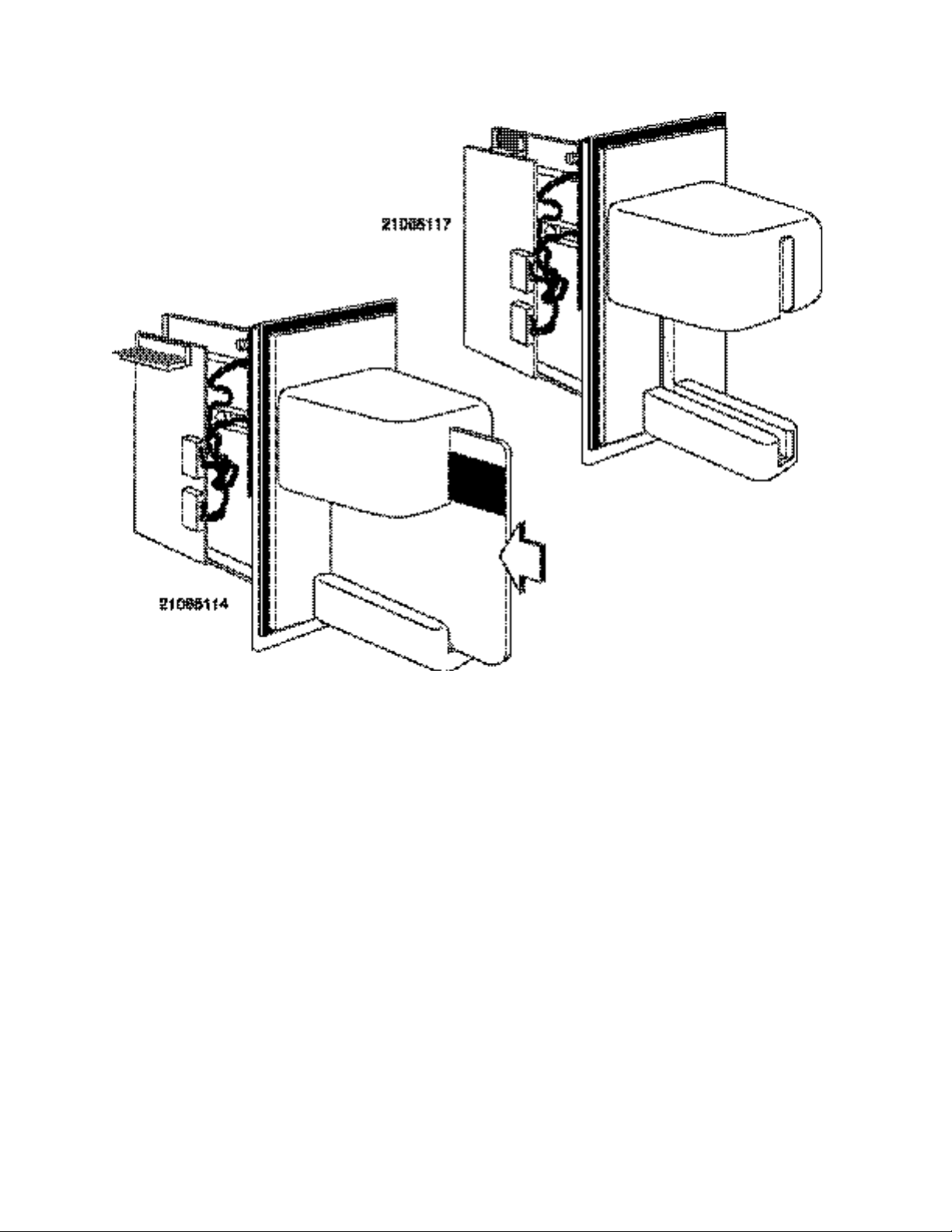
Figure 1-1. P-series Insertion Readers with Bezels
vi
Page 7

1
Part Number
Heads
Tracks
Bezel
I/O Connector
21065114
2
1, 2
Extended Arm Bezel
9-pin Header
21065117
2
1, 2
Extended Arm Bezel
7-pin Header
Part Number
Description
21064519
Angle Bracket Mounting Kit
SECTION 1. FEATURES AND SPECIFICATIONS
The P-series Insertion Readers are designed for use at fuel pumps or other harsh outdoor
environments that require a moisture resistant reader. The Readers are electronically TTL-level
compatible and mechanically compatible with the industry-standard footprint. The Readers are
configured to ISO standard 7811 for reading Tracks 1 and 2 on the magnetic stripe.
FEATURES
Features of the Readers are as follows:
• Dual Read-Head Capability - allows for easier card orientation when inserted into the
Reader. Also supports single read head with no chassis modification
• Beam-mounted Read-heads - improves card tracking capabilities for reading warped or
wavy cards
• Sealed Chassis Design - provides superior resistance to moisture
• AGC (Automatic Gain Control) in MagTek IC's - enhances mag-stripe read performance
• Ruggedized Chassis and Bezel Material - improves temperature and impact performance
CONFIGURATIONS
Table 1-1 lists the part numbers, number of heads, bezel, and connector information.
Table 1-1. Configurations
Accessories
The accessories are as follows:
Page 8

P-series Insertion Reader
RELATED DOCUMENTS
The P-series Readers will read cards that meet the standards defined by ISO (International
Standards Organization):
ISO 7811 Identification Cards - Mag-stripe Cards, Tracks 1-3
ISO 7810 Identification Cards - Physical Specifications (ID-1 Cards)
Available from ANSI, Phone 212-642-4900; www.ANSI.org.
For further information about magnetic stripe readers, refer to MagTek part number 99875148,
I/O Interface for TTL Magnetic Stripe Readers, Technical Reference Manual.
2
Page 9

3
ELECTRICAL
+5 VDC ±10%.
Current Draw:
Less than 12 mA
MTBF:
Electronics: 125,000 hours. Head: 1,000,000 passes
(500,000 insert cycles)
Output Signal Levels
Vol = 0.4 V @ 2.0 mA
V
oh
= Vcc – 0.5V @ 2.0 mA
Interface:
TTL level.
Dielectric Strength:
DC250 volts, 1 minute
Insulation Resistance:
Greater than 10 M ohms at DC 250V
(Measured between PCB ground and frame).
Mag-Stripe Read:
TK2:
75 or 210 BPI (MagTek decode ASIC is density independent).
MECHANICAL
Dimensions:
Without Bezel With Extended Arm Bezel
Length:
4.08" (103.6 mm) 4.82" (122.4 mm)
Width:
3.15" (80.0 mm) 3.54" (90.0 mm)
Height:
1.29" (32.8 mm) 1.81" (46.0 mm)
Weight:
3.5 oz. (100 g ±20%)
I/O Connector Type:
For P/N 21065114: 9-pin straight locking header, AMP P/N 640456-9
P/N MLAS100-7.
specifications supported:
ISO/ANSI/AAMVA/CDL/ 75 or 210BPI on track 2 (normally 75 bpi)
ENVIRONMENTAL
Temperature
Storage:
-22 oF to 158 oF (-30 oC to 70 oC)
Humidity:
Storage:
10% to 90% non-condensing
Altitude
Storage:
0 - 50,000 ft. (15,240m)
SPECIFICATIONS
Specifications for the Readers are listed in Table 1-2.
Table 1-2. Specifications
Input Voltage
Recording Method:
Card Speed:
TK1:
MSR read-data format
Operating:
Operating:
Operating:
Two-Frequency Coherent Phase (F/2F).
3 to 50 IPS and 210 BPI (7.6 to 127 cm/sec)
75 or 210 BPI (MagTek decode ASIC is density independent).
For P/N 21065117: Right angle 7-pin locking header, ITW Pancon
ISO/ANSI/AAMVA/CDL/ 75 or 210BPI on track 1 (normally 210 bpi)
-22 oF to 140 oF (-30 oC to 60 oC)
10% to 90% non-condensing
0 - 10,000 ft. (3,048m)
Page 10

P-series Insertion Reader
4
Page 11

5
SECTION 2. INSTALLATION
The reader is supplied with or without a bezel. The user provides all mounting hardware such as
brackets, screws, or anything else required to affix the Reader to the pump.
MECHANICAL INS TALLATION
Figure 2-1 shows the 9-pin header, head connectors, and the card orientation of Reader P/N
21065114.
The standard orientation of the Reader is with the larger guide up as shown in the illustration.
Although any orientation may be used, this position offers the best protection for the heads from
moisture, dust, or foreign particles.
Figure 2-1. Mounting Guides and Card Insertion
The recommended method of installation is to position the Reader between two brackets from
the inside of a mounting panel, as indicated in Figure 2-2. The large gasket on the bezel presses
against the bracket to prevent moisture from entering. Another bracket is positioned and secured
over the bezel to hold the Reader firmly against the first bracket.
Page 12

P-series Insertion Reader
Figure 2-2. MagTek Bezel Mounting Position
OPTIONAL MOUNTING BRACKET
In applications where moisture-intrusion is a concern, it is recommended that the reader be
mounted with a 4o - 5o downward angle with respect to the horizontal plane. This will allow
gravity to drain away any excess moisture that may have entered into the Card Reader slot.
For more information about the mounting bracket kit (21064519) that can be used to tip the
reader forward, contact your MagTek salesperson.
CARD INSERTION
The card must be inserted with the magnetic stripe in the larger guide, as shown in Figure 2-1. If
there are two heads in the unit, the magnetic stripe may be facing in either direction but must be
in the larger guide. If there is only one head in the unit, the primary position of the head is on the
same side of the unit as the PCB. The secondary position of the single head is on the side
opposite the PCB. When a single head is used, the magnetic stripe must always face the position
of the head.
6
Page 13

Section 2. Installation
7
Pin Number
Signal
Description
rear of the unit.
2
Track 2 Data
Active low
3
Card Present
Active low
4
Track 2 Strobe
Valid data with falling edge
5
Key
No Connection
6
Vcc
+5VDC
7
Gnd
Ground
8
Track 1 Strobe
Valid data with falling edge
9
Track 1 Data
Active low
Pin Number
Signal
Description
1
Vcc
+5VDC
2
Track 1 Data
Active low
3
Track 1 Strobe
Valid data with falling edge
4
Track 2 Data
Active low
5
Track 2 Strobe
Valid data with falling edge
rear of the unit.
7
Gnd
Ground
CABLE CONNECTIONS AND PIN LISTS
The cable connections to the host are J3 on the PCB. Table 2-1 lists the pins and signals for the
9-pin connector, and Table 2-2 lists the pins and signals for the 7-pin connectors.
Table 2-1. 9-pin I/O Header, J3, Pin List (P/N 21065114)
1 Back Sensor Active low when the card is at the
Header: AMP P/N 640456-9
Mates: AMP P/N 640442-9 (one in a series of 50 – see AMP catalog)
Table 2-2. 7-pin I/O Header, J3, Pin List (P/N 21065117)
6 Back Sensor Active high when the card is at the
Header: ITW Pancon P/N MLAS100-7
Mates: ITW Pancon P/N CE100F28-7, CE100F26-7, CE100F24-7, CE100F22-7
Back Sensor and Card Present
The back sensor is active low when the card is fully inserted at the back of the unit. If a Card
Present signal is used as with P/N21065114 (See Table 2-1 above), the movement of an encoded
magnetic stripe past the read head generates the signal active low. These two signals are gated to
reduce the dwell time needed before the read-on-withdrawal can be initiated. On P/N 21065117,
Back Sensor is active high.
Track Data
Tracks 1 and 2 data signals are active low when data is read. See Timing below.
Page 14

P-series Insertion Reader
Strobe
The Strobe signal is active with the falling edge of the pulse. See Timing below.
HEADERS, CONNECTORS, AND CARD ORIENTATION
Figure 2-4 shows the 9-pin header, head connectors, and pin 1 for connection for Reader P/N
21065114. Figure 2-5 shows the 7-pin header, head connectors, and pin 1 for connections for
Reader P/N 21065117.
8
Figure 2-4. I/O Header, Connectors, and Card Orientation, P/N 21065114
Figure 2-5. I/O Header and Connectors, P/N 21065117
Page 15

Section 2. Installation
9
ACTIVE DATA
NOTE 1
NOTE 1
NOTE 1
NOT TO SCALE
HEAD OUTPUT
SIGNAL
INTERNAL CARD
PRESENT
P/N 21065114
NOTE 1:
TIMING FOR BACK SENSOR AND CARD PRESE NT
Figure 2-6 shows the timing for the Back Sensor and the Card Present signals.
The card is read in both directions (on insertion and withdrawal), but the data is active on
withdrawal.
TIME OF INSERTION
TIME OF WITHDRAWAL
BACK SENSOR
CARD PRESENT
AT CONNECTOR
Used on only
P/N 21065114
ACTIVE DATA
MOST RELIABLE
BACK SENSOR
P/N 21065117
Time out of the internal card present signal occurs approximately 150 ms
after the last strobe transition. The internal card present signal becomes
active when the movement of an encoded magnetic stripe past the read
head generates a signal. The back sensor and internal card present are
gated together to reduce the dwell time needed before the read-onwithdrawal can be initiated and is output as card present at the connector.
Figure 2-6. Timing for Card Present and Back Sensor Signals
While it is possible for the Card Reader to read data on either the insertion or withdrawal stroke,
it should be noted that card reading is most reliable during the card withdrawal stroke. For this
reason MagTek recommends that customer’s software should be designed to emphasize data
capture during the card withdrawal stroke. For the most reliable operation: Read the card upon
insertion, when the card present goes high, check for errors, if no errors, output the data, start
sentinel first, after the card is withdrawn. If an error is detected, clear the stored data and read
the card on withdrawal, if no errors, output the data, start sentinel first, otherwise output an error
indication or a try again message.
Page 16

NOTES
0
1 1
0 0 0 0 0 ...
DATA
1 1 1
BIT
NOTE 3
STROBE
NOTE 2
NOTE 1
P-series Insertion Reader
TIMING FOR DATA AND STROBE
Figure 2-7 shows the timing for Data and Strobe. The timing shown is for active data (see
Figure 2-6).
INTERNAL
CARD PRESENT
0 0
STROBE WIDTH
APPROXIMATELY
25-50% OF BIT TIME
1. TIME OUT OF THE CARD PRESENT SIGNAL OCCURS
APPROXIMATELY 150 MS AFTER THE LAST STROBE TRANSITION.
2. DATA IS VALID 1.0 µS (MINIMUM) BEFORE THE NEGATIVE EDGE OF
STROBE.
3. 6 OR 7 HEAD FLUX REVERSALS ARE IGNORED FOR LOW DENSITY
CONFIGURATION AND 14 OR 15 FOR HIGH DENSITY
CONFIGURATION.
Figure 2-7. Data and Strobe Timing
Card Present
The Card Present signal (used in P/N 21065114) is low when a recorded card is being moved
across the read head. The Card Present signal is gated with the back sensor to ensure that Card
Present will go high when the card is fully inserted into the Reader.
Data
The Data signal is valid while the Strobe is low. If the Data signal is high, the bit is a zero.
10
Page 17

Section 2. Installation
11
Strobe
The Strobe signal indicates when Data is valid. It is recommended that Data be loaded by the
user with the leading edge (negative) of the Strobe.
Figure 2-8 may be used for mounting the Reader.
For further information about magnetic stripe readers, refer to MagTek part number 99875148,
I/O Interface for TTL Magnetic Stripe Readers, Technical Reference Manual.
Page 18

P-series Insertion Reader
12
XX = Inches
(XX) = millimeters
Figure 2-8. Dimensions for Mounting
 Loading...