

Page 1

MODEL MT-215232
RS-232 INSERTION READER
TECHNICAL REFERENCE MANUAL
Manual Part Number 99821504 Rev 6
APRIL 2003
REGISTERED TO ISO 9001:2000
1710 Apollo Court
Seal Beach, CA 90740
Phone: (562) 546-6400
FAX: (562) 546-6301
Technical Support: (651) 415-6800
www.magtek.com
Page 2

Copyright© 1996-2005
MagTek®, Inc.
Printed in the United States of America
Information in this document is subject to change without notice. No part of this document may be
reproduced or transmitted in any form or by any means, electronic or mechanical, for any purpose,
without the express written permission of MagTek, Inc.
MagTek is a registered trademark of MagTek, Inc.
REVISIONS
Rev Number Date Notes
2 5/3/96 Previous versions not assigned Rev Numbers
3 4/28/98 Changed Warranty to 90 days. Added Tech Support
Phone Number.
4 01/01/01 Added MagTek Web address. Changed copyright
date. Changed Warranty to one year. Added Agency
Approvals.
5 07/29/02 Sec 1: First paragraph, adds AAMVA and CDL reads
Trk 2 only; Configurations, deletes all current P/Ns
and adds 2 new P/Ns; Specs, replaces Sprague with
TI; Changes output driver OFF value from 30 to 50 V,
Changed weight from 6 to 5 oz, Table 1-2, editorial.
Sec 2: Switch Setting SWA, Table 2-1, added 150 to
Baud Rate. Sec 3: Table 3-3 broken into 2 tables for
clarity, Clarified signals and power and connectors,
Clarified LED connections and indicators, Clarified
user drivers. Sec 4: removed.
6 08 Apr 03 Front Matter: added ISO line to logo, changed Tech
Support phone number, changed to new warranty,
changed warranty from 90 days to 1 year.
ii
Page 3

LIMITED WARRANTY
MagTek warrants that the products sold to Reseller pursuant to this Agreement will perform in accordance with
MagTek’s published specifications. This warranty shall be provided only for a period of one year from the da
of the shipment of the product from MagTek (the “Warranty Period”). This warranty shall apply only to the
original purchaser unless the buyer is aut
shall apply only to the first repurchase.
horized by MagTek to resell the products, in which event, this warranty
te
During the Warranty Period, should this product fail to conform to MagTek’s specifications, MagTek wi
option, repair or replace this product at no additional charge except as set forth below. Repair parts and
replacement products will be furnished on an exchange basis and will be either reconditioned or new. All rep
parts and products become the property of MagTek. This limited warranty does not include service to repair
damage to the product resulting from accident, disaster, unreasonable use, misuse, abuse, customer’s negligenc
Reseller’s negligence, or non-MagTek modification of the product. MagT
alleged defective goods to determine whether the warranty is applicable.
Without limiting the generality of the foregoing, MagTek specifically disclaims any liability or warranty for
goods resold in other than MagTek’s original packages, and for goods modified, altered, or treated by customers
Service may be obtained by delivering the product during the warranty period to MagTek (1710 Apollo Court,
Seal Beach, CA 90740). If this product is delivered by mail or by an equivalent shipping carrier, the customer
agrees to insure the product or assume the risk of loss or damage in transit, to prepay shipping charges to the
warranty service location and to use the original shipping container or equivalent. MagTek will return the produc
prepaid, via
all returns.
MAGTEK MAKES NO OTHER WARRANTY, EXPRESS OR IMPLIED, AND MAGTEK DISCLAIMS AN
WARRANTY OF ANY OTHER KIND, INCLU
FITNESS FOR A PARTICULAR PURPOSE.
EACH PURCHASER UNDERSTANDS THAT THE MAGTEK PRODUCT IS OFFERED AS IS. IF THIS
PRODUCT DOES NOT CONFORM TO MAGTEK’S SPECIFICATIONS, THE SOLE REMEDY SHALL BE
REPAIR OR REPLACEMENT AS PROVIDED ABOVE. MAGTEK’S LIABILITY, IF ANY, TO RESELLER
OR TO RESELLER’S CUSTOMERS, SHALL IN NO EVENT EXCEED THE TOTAL AMOUNT PAID TO
MAGTEK BY RESELLER UNDER THIS AGREEMENT. IN NO EVENT WILL MAGTEK BE LIABLE T
THE RESELLER OR THE RESELLER’S CUSTOMER FOR ANY DAMAGES, INCLUDING ANY LOST
PROFITS, LOST SAVINGS OR OTHER INCIDENTAL OR CONSEQUENTIAL DAMAGES ARISING OUT
OF THE USE OF OR INABILITY TO USE SUCH PRODUCT, EVEN IF MAGTEK HAS BEEN A
HE POSSIBILITY OF SUCH DAMAGES, OR FOR ANY CLAIM BY ANY OTHER PARTY.
T
LIMITATION ON LIABILITY
a three (3) day shipping service. A Return Material Authorization (RMA) number must accompany
DING ANY WARRANTY OF MERCHANTABILITY OR
ek reserves the right to examine the
ll, at its
laced
e,
Y
O
DVISED OF
.
t,
EXCEPT AS PROVIDED IN THE SECTIONS RELATING TO MAGTEK’S LIMITED WARRANTY,
MAGTEK’S LIA
PRODUCTS.
MAGTEK MAKES NO OTHER WARRANTIES WITH RESPECT TO THE PRODUCTS, EXPRESSED OR
IMPLIED, EXCEPT AS MAY BE STATED IN THIS AGREEMENT, AND MAGTEK DISCLAIMS A
IMPLIED WARRANTY, INCLUDING WITHOUT LIMITATION ANY IM
MERCHANTABILITY OR FITNESS FOR A PARTICULAR PURPOSE.
MAGTEK SHALL NOT BE LIABLE FOR CONTINGENT, INCIDENTAL, OR CONSEQUENTIAL
DAMAGES TO PERSONS OR PROPERTY. MAGTEK FURTHER LIMITS ITS LIABILITY OF ANY
WITH RESPECT TO THE PRODUCTS, IN
CONTRACT PRICE FOR THE GOODS.
MAGTEK’S SOLE LIABILITY AND BUYER’S EXCLUSIVE REMEDIES ARE
AND IN THE SECTION RELATING TO MAGTEK’S LIMITED WARRANTY.
BILITY UNDER THIS AGREEMENT IS LIMITED TO THE CONTRACT PRICE OF THE
NY
PLIED WARRANTY OF
KIND
CLUDING ANY NEGLIGENCE ON ITS PART, TO THE
STATED IN THIS SECTION
iii
Page 4

FCC WARNING STATEMENT
This equipment has been tested and found to comply with the limits for a Class A digital device, pursuant to Part
15 of FCC Rules. These limits are designed to provide reasonable protection against harmful interference when
the equipment is operated in a commercial environment. This equipment generates, uses, and can radiate radio
frequency energy and, if not installed and used in accordance with the instruction manual, may cause harmful
interference to radio communications. Operation of this equipment in a residential area is likely to cause harmful
interference in which case the user will be required to correct the interference at his own expense.
FCC COMPLIANCE STATEMENT
This device complies with Part 15 Of The FCC Rules. Operation of this device is subject to the following two
conditions: (1) This device may not cause harmful interference. And (2) This device must accept any interference
received, including interference that may cause undesired operation.
CANADIAN DOC STATEMENT
This digital apparatus does not exceed the Class A limits for radio noise for digital apparatus set out in the Radio
Interference Regulations of the Canadian Department of Communications.
Le présent appareil numérique n’émet pas de bruits radioélectriques dépassant les limites applicables aux
appareils numériques de las classe A prescrites dans le Réglement sur le brouillage radioélectrique édicté par les
ministère des Communications du Canada.
CE STANDARDS
Testing for compliance to CE requirements was performed by an independent laboratory. The unit under test was
found compliant to Class A.
UL/CSA
This product is recognized per Underwriter Laboratories and Canadian Underwriter Laboratories 1950.
iv
Page 5

TABLE OF CONTENTS
CTION 1. FEATURES AND SPECIFICATIONS--------------------------------------------------------------------- 1
SE
FEATURES--------------------------------------------------------------------------------------------------------------------- 1
M
ODES OF OPERATION -------------------------------------------------------------------------------------------------- 2
Unbuffered Mode..................................................................................................................................2
Buffered Mode......................................................................................................................................2
CONFIGURATIONS---------------------------------------------------------------------------------------------------------- 3
SPECIFICATIONS------------------------------------------------------------------------------------------------------------ 4
PIN LIST AND I/O SIGNALS----------------------------------------------------------------------------------------------- 6
SECTION 2. IN
MOUNTING -------------------------------------------------------------------------------------------------------------------- 7
SW
ITCH SETTINGS ---------------------------------------------------------------------------------------------------------9
Switch SWA..........................................................................................................................................9
Switch SWB........................................................................................................................................10
SE
CTION 3. COMMANDS, FORMATS, TIMING-----------------------------------------------------------------------13
HOST TO READER COMMANDS---------------------------------------------------------------------------------------13
RE
ADER TO HOST FORMATS------------------------------------------------------------------------------------------13
Successful Card Read........................................................................................................................14
Unsuccessful Card Read....................................................................................................................15
No Card Read.....................................................................................................................................16
IN
TERFACE WIRE LIST FOR MT-215232----------------------------------------------------------------------------17
Control Signals ...................................................................................................................................17
Power and Connector Mating.............................................................................................................17
LED Connections................................................................................................................................19
TIMING -------------------------------------------------------------------------------------------------------------------------20
INDICATORS -----------------------------------------------------------------------------------------------------------------20
USER DRIVERS -------------------------------------------------------------------------------------------------------------21
Figure 1-1. RS-232 Insertion Reader ---------------------------------------------------------------------------------------vi
Figure 1-2. Dimensions---------------------------------------------------------------------------------------------------------5
Figure 2-1. Switches and Connector---------------------------------------------------------------------------------------- 7
Figure 2-2. Mounting Dimensions-------------------------------------------------------------------------------------------- 8
Figure 3-1. Successful Card Read------------------------------------------------------------------------------------------14
Figure 3-2. Unsuccessful Card Read --------------------------------------------------------------------------------------15
Figure 3-3. No Card Read ----------------------------------------------------------------------------------------------------16
F
igure 3-4. Transmission Timing--------------------------------------------------------------------------------------------20
Table 1-1. Specifications------------------------------------------------------------------------------------------------------- 4
Table 1-2. J2 Connector Signals--------------------------------------------------------------------------------------------- 6
Table 2-1. Baud Rate Setting ------------------------------------------------------------------------------------------------- 9
Table 2-2. Parity Setting-------------------------------------------------------------------------------------------------------- 9
Table 3-1. Commands and Responses - I and R Commands -------------------------------------------------------13
Table 3-2. Commands and Responses – Auxiliary Driver Commands--------------------------------------------13
Table 3-3. D9 Without Control Signals ------------------------------------------------------------------------------------18
Table 3-4. D25 Without Control Signals-----------------------------------------------------------------------------------18
Table 3-5. D9 With Control Signals-----------------------------------------------------------------------------------------19
T
able 3-6. D25 With Control Signals---------------------------------------------------------------------------------------19
STALLATION ------------------------------------------------------------------------------------------------ 7
ILLUSTRATIONS
TABLES
v
Page 6
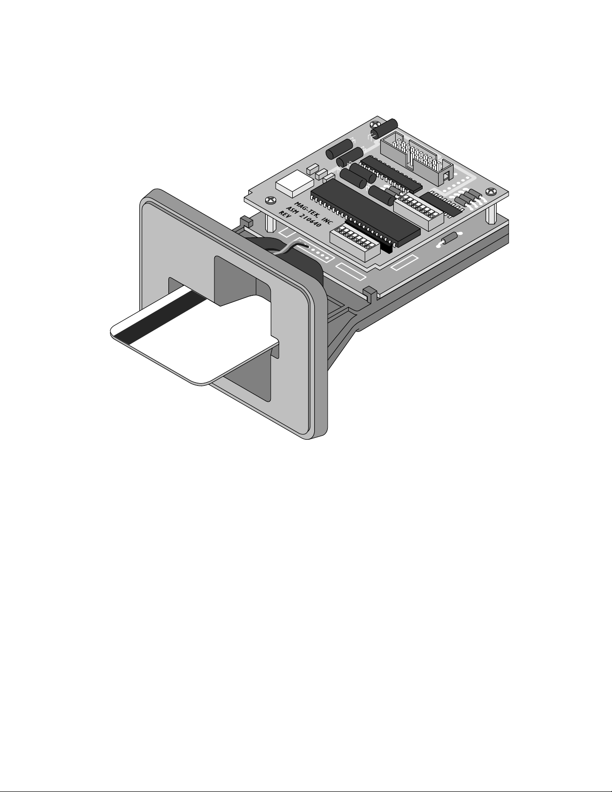
Figure 1-1. RS-232 Insertion Reader
vi
Page 7

SECTION 1. FEATURES AND SPECIFICATIONS
The Model MT-215232 Insertion Reader is a magnetic
ual tracks of alphanumeric or numeric data in formats established by the credit card industry.
d
For AAMVA and CDL, the Reader reads track 2 only.
The Reader is compatible with the PC AT/PS2 series of perso
ith an RS-232 interface. The MT-215 will read cards that meet the standards defined by ISO
w
7810, 7811-1, 7811-2, 7811-3, 7811-4, 7811-5, and 7811-6.
card is inserted all the way into the reader and withdrawn with a steady motion. A read
A
attempt is made during insertion and removal of the card.
Two blocks of eight switches each select the RS-232 pro
aming characters. The switches also select buffered and unbuffered modes of operation and
fr
enable comma
FEATURES
Major features of the Insertion Reader are as follows:
nd selection from the Host to the Reader.
• Hardware compatible with PC or any computer with an RS-23
• Switch selectable buffered o
• Switch selectable baud ra
r unbuffered modes of operation
te
• Switch selectable parity
On/off switches for STX (Start of Text), ETX (End of Text), and ESC (ESCAPE) framing
•
characters.
• On/off switch for CR (Carriage Return)
• Magnetic stripe read dur
ing insertion and removal of card
• ASCII message format
• Two auxiliary drivers for Reader status, or to actuate devices such as solenoids, or relays
stripe card reader, which reads single or
nal computers or any computer
tocol including baud rate, parity, and
2 interface.
1
Page 8

MT-215232 Insertion Reader
MODES OF OPERATION
The Reader can operate in either unbuffered or buffered mode. The descriptions are as follows:
Unbuffered Mode
When a card is inserted and removed, a read attempt is made during both insertion and removal.
Upon removal of the card if the read is successful, data (including the two sentinel characters) is
sent to the Host. The data is transmitted immediately and not retained in the Reader.
When operating in the unbuffered mode, the Reader does not need to received commands from
the Host in order to transmit data or status characters; however, the Reader does respond to an
“Inquiry Command” by sending status characters. The inquiry command that requests the
transmission of status characters is the ESCAPE (ESC) character followed by the ASCII
character “I”.
The Reader must be turned off before selecting the operating mode. Refer to Section 2 for
switch settings.
Note
The insertion and removal of the card must be done in a
continuous motion. If not, the Reader may not read the encoded
data properly. In that case, the Reader responds by either
transmitting the ASCII character “E” representing an error, or by
not transmitting any character, which indicates that the Reader
has not detected data and the card was not completely inserted.
Buffered Mode
When a card is inserted and removed, a read attempt is made during both insertion and removal.
Upon removal of the card if the read is successful, data (including the two sentinel characters) is
stored in a memory buffer on the Reader and is not transmitted until the Reader receives an
“Inquiry Command” from the Host. This command is the ESCAPE character followed by the
ASCII “I”. The Reader cannot read another card until the buffer is cleared. To clear the buffer,
the Host must transmit the ESCAPE character followed by The ASCII “R”.
The Reader must be turned off before selecting the operating mode. Refer to Section 2 for
switch settings
2
Page 9

Section 1. Features and Specifications
Note
The insertion and removal of the card must be done in a
continuous motion. If not, the Reader may not read the encoded
data properly. In that case, the Reader responds to an inquiry
command by either transmitting the ASCII character “E””
representing an error, or by just transmitting status characters,
which indicates that the Reader has not detected any data and the
card was not completely inserted.
CONFIGURATIONS
The following list includes part numbers and available track configurations:
Part Number Read Bezel
Multiple Tracks
21065127
21065132
Tracks 1, 2
Tracks 1, 2
No Bezel
Flat Face Bezel
3
Page 10

MT-215232 Insertion Reader
SPECIFICATIONS
Table 1-1 lists the specifications for the RS-232 Insertion Reader.
Table 1-1. Specifications
OPERATING
Reference Standards ANSI/ISO
Power Input +5V DC - Requires +4.75 V DC to +5.25 V DC @ 0.045 A
Power Consumption 0.225 WATTS
Auxiliary Drivers 1 and 2 Open Collector outputs, capable of driving visual indicators, solenoids,
relays, etc. Outputs driven by Texas Instruments ULN 2003AN. Any
use of these drivers must meet the following: ON = 0.8V @ 0.2 amps
max. OFF = 50.0V max. (See Texas Instruments Data Sheet for
parameters.)
Interface Signal RS-232E
Message Format ASCII (7 Data Bits + Parity Bit)
Track Card Speed TRK 1 or 3: 3 to 50 IPS (127 cm) at 210 BPI.
TRK 2: 3 to 50 IPS (127 cm) at 75 BPI
MTBF Electronics: 120,000 hours
Head: 1,000,000 passes (500,000 insertion cycles)
MECHANICAL
Dimensions (with Bezel)
Length
Width
Height
Bezel Thickness
Weight 5.42 oz. (154 g.)
Temperature
Operating 0oC to 70oC (32oF to 158oF)
Storage -40oC to 80oC (-40oF to 176oF)
Humidity
Operating 10% to 90% noncondensing
Storage 0% to 100% noncondensing
Altitude
Operating 0-10,000 ft. (0-3,048 m.)
Storage 0-50,000 ft. (0-15,240 m.)
4.58 “ (11.63cm)
4” (10.16 cm)
3” (7.62 cm)
0.31” (0.79 cm)
ENVIRONMENTAL
4
Page 11

Section 1. Features and Specifications
Figure 1-2. Dimensions
5
Page 12

MT-215232 Insertion Reader
PIN LIST AND I/O SIGNALS
Table 1-2 lists the pin numbers, signals, and descriptions for connector J2 on the Reader. See
Section 3 for the Interface Wire List for the MT215232.
Table 1-2. J2 Connector Signals
Pin
Number
1,2 +5v
3,4 GND
5 DSR
6
7 DTR
8* AUX 1
9 CTS
10* AUX 2
11 RTS
12
13 RD
14***
15 TD
16*** BUSY
17** N/C
18*** READY
19** N/C
20*** ERROR
*These signals are open collector outputs, capable of driving visual indicators, solenoids, relays, etc. The
outputs are driven by a Texas Instruments ULN 2003AN. Any use of these drivers must meet the
following specifications: ON = 0.8V @0.2 amps max. OFF = 50.0V max.
**The 5V to +12V/-12V conversion is now being done on the processor board. Pins 17 and 19 (which
formerly transmitted the +12V/-12V) now have no connection so that the new version of the Reader can
be used interchangeably with the old version of the Reader.
***See Section 3 for details and mating connectors.
Signal Description
Either one or both pins can be connected to a +5V power supply. See Specifications,
Section 1 for ratings.
Either one or both pins can be used as circuit ground.
Data Set Ready, RS-232E signal. Indicates to the Reader that the Host is active.
Used for factory testing only.
Data Terminal Ready, RS-232 signal. Indicates to the Host that the Reader is active.
Auxiliary driver 1. Operated by commands from the Host.
Clear to sent, RS-232C signal. Signal from the Host to the Reader allowing data to be
transmitted.
Auxiliary driver 2. Operated by commands from the Host.
Request to send, RS-232E signal. The Reader transmits the signal to the Host
indicating the Reader is ready to transmit data.
CARD
PRESENT Used for factory testing only.
Received data, RS-232E signal. Reader receives data sent from the Host.
REAR
SENSOR
BLOCKED
Indicates the presence of a card when it is fully inserted in the reader.
Transmitted data, RS-232E signal. Transmits data from the Reader to the Host.
Used for factory testing only.
In previous versions of the Reader this pin was used for -12V.
Indicates the unit is ready to accept a card.
In previous versions of the Reader this pin was used for +12V.
Indicates an unsuccessful read attempt. This signal remains active for 2.0 seconds.
6
Page 13

SECTION 2. INSTALLATION
The installation consists of mounting the Reader, connecting the cable, and settings the switches.
Other considerations such as commands, responses, formats and timing are given in Section 3.
The switches and the connector are shown in Figure 2-1. The pin list for the connector is
presented in Section 1 under Specifications. The illustration in Section 1 also shows clearance
dimensions of the Reader.
Figure 2-1. Switches and Connector
MOUNTING
Figure 2-2 shows dimensions for mounting considerations.
7
Page 14

MT-215232 Insertion Reader
8
Figure 2-2. Mounting Dimensions
Page 15

Section 2. Installation
SWITCH SETTINGS
The switch positions and orientations are shown in Figure 2-1. The switches must be set while
power is off to ensure that the switch settings are properly loaded. As shown in the illustration
and designated on the printed circuit board, the switches are SWA and SWB. Set the switches as
described below.
Switch SWA
On SWA switches 1, 2 and 3 set the baud rate. This is the rate at which data is transmitted and
received between the Reader and the Host. The switch settings are shown in Table 2-1.
Table 2-1. Baud Rate Setting
BAUD RATE SWA1 SWA2 SWA3
150 ON ON ON
300 OFF ON ON
600 ON OFF ON
1200 OFF OFF ON
2400 ON ON OFF
4800 OFF ON OFF
9600 ON OFF OFF
19200 OFF OFF OFF
On SWA switches 4 and 5 set the parity as shown in Table 2-2.
Table 2-2. Parity Setting
PARITY SENT SWA4 SWA5 RECEIVED
PARITY CHECK
ODD ON ON ODD
EVEN OFF ON EVEN
ONE (MARK ) ON OFF IGNORED
ZERO (SPACE) OFF OFF IGNORED
SWA6:
Sets the Start of Text (STX) framing character. This character is optional. Set SW6 to ON if
STX is required and to OFF if it is not.
9
Page 16

MT-215232 Insertion Reader
SWA7:
Sets the ESCAPE character. This character is optional. Set SW7 to ON if ESCAPE is
implemented and OFF if it is not.
SWA8:
Sets the End of Text (ETX) framing character. This character is optional. Set SW8 to ON if
ETX is implemented and OFF if it is not.
Switch SWB
SWB1:
Sets the Carriage Return (CR). This character is optional. Set SWB1 to ON if CR is to be
implemented and OFF if it is not.
SWB2:
Sets the operating mode of Buffered or Unbuffered. Set SWB2 to ON for Buffered or OFF for
Unbuffered.
SWB3:
Two open collector auxiliary drivers are available to the user. The status of these drivers is
reported by the bytes of information following the transmitted card data. If the drivers are not
used, these status bytes may be suppressed by setting the switch to OFF. The status bytes are
transmitted if the switch is set to ON.
SWB4:
Factory set to ON for “I” and “R”, OFF for “+” and “-” See Section 3, Operation, under Host to
Reader Commands.
SWB5:
Factory set to OFF (must not be changed).
10
Page 17

Section 2. Installation
SWB6:
Factory set to OFF (for the most reliable operation should not be changed). Reader will read
upon insertion and withdrawal. If set to the ON position, the Reader will read on Insert only.
Data is transmitted upon contact of the rear sensor.
SWB7:
Set to the ON position to jumper the control signals RTS-CTS. Set to OFF is these signals are
implemented by the Host.
SWB8:
Set to the ON position to jumper the control signals DSR-DTR. Set to OFF is these signals are
implemented by the Host.
Notes:
1. In previous versions of the Reader, a switch was used to enable reading either a 5-bit
data format or a 7-bit data format. In this version the function of reading a 7- or 5-bit
format is performed automatically by the firmware.
2. Switches that are factory set must be set in the position indicated when used by the
customer. The Reader is one of a series of products using the same microcontroller. The
factory set switches make the microcontroller function properly in the Reader.
11
Page 18

MT-215232 Insertion Reader
12
Page 19

SECTION 3. COMMANDS, FORMATS, TIMING
This section includes commands from the Host to the Reader, Reader to Host message formats,
transmission timing, and possible uses of drivers.
HOST TO READER COMMANDS
All commands transmitted from the Host to the Reader must be preceded by the ASCII “ESCAPE”
character. These command messages may contain other framing characters, which are ignored by the
Reader. Table 3-1 describes I and R commands, a switch selectable option for the ASCII command
character and the Reader response to the Host. Table 3-2 describes the second character commands
Table 3-1. Commands and Responses - I and R Commands
HOST COMMANDS READER RESPONSES
ASCII “ESCAPE”
CHARACTER
(1B hex)
<ESC> I + Inquiry command causes the
<ESC> R - Release command causes the
Table 3-2. Commands and Responses – Auxiliary Driver Commands
ASCII “ESCAPE”
CHARACTER
(1B hex)
READER TO HOST FORMATS
The following diagrams represent the formats of the data transmitted after a successful card read, an
unsuccessful card read, and no card read which is the response if the Host inquires and the buffer is
empty.
SWITCH SELECTABLE ASCII
CHARACTER - SWB4
ON OFF
Reader to transmit data, error, or
status message.
Reader to clear its memory buffer of
any data present. This command
works only in the Buffered mode.
ASCII SECOND
CHARACTER
<ESC> 0 Deactivates both user drivers 1 and
<ESC> 1 Activates user driver 1.
<ESC> 2 Activates user driver 2.
<ESC> 3 Deactivates user driver 1.
<ESC> 4 Deactivates user driver 2
READER RESPONSES
2.
13
Page 20

MT-215232 Insertion Reader
Successful Card Read
<STX> <ESC> SS CARD
DATA
ES USER DRIVER
STATUS
CARD SENSOR
STATUS
<CR> <ETX>
End of Text
Character,
(03 Hex)
Optional.
Set SWA # 8
to ON
Carriage Return
Character (OD Hex)
Optional. Set SWB #1
to ON.
ASCII “0” = No Card is in the Reader
ASCII “1” = Card present in the Reader
ASCII”0” = Drivers 1 and 2 OFF
ASCII”1” = Driver 1 ON
ASCII”2” = Driver 2 ON
ASCII”3” = Drivers 1 and 2 ON
Set SWB #3 ON
End Sentinel Character ASCII “?”
Card Data in ASCII Track Order
i.e., Tk 1 and 2 for a Tk 1 and 2 device, or
Tk 2 and 3 for a Tk 2 and 3 device
Start Sentinel Character
ASCII “%” for Track 1
ASCII “;” for Tracks 2 and 3
Escape character, optional
(1B hex), set SWA #7 to ON
Start of Text Character, optional (02 hex),
Set SWA #6 to ON
Notes: 1. Optional characters are used to frame the data.
2. The LRC character is not transmitted.
3. The optional Hex characters are shown with the parity bit as zero (“0”).
Figure 3-1. Successful Card Read
14
Page 21

Section 3. Commands, Formats, and Timing
Unsuccessful Card Read
<STX> <ESC> ERROR USER DRIVER
STATUS
CARD SENSOR
STATUS
<CR> <ETX>
End of Text
Character,
(03 Hex)
Optional.
Set SWA # 8
to ON
Carriage Return
Character (OD Hex)
Optional. Set SWB #1
to ON.
ASCII “0” = No Card is in the Reader
ASCII “1” = Card present in the Reader
ASCII”0” = Drivers 1 and 2 OFF
ASCII”1” = Driver 1 ON
ASCII”2” = Driver 2 ON
ASCII”3” = Drivers 1 and 2 ON
Set SWB #3 ON
ASCII “E” represents error. If both tracks fail
on a dual track reader, an “EE” will be transmitted.
If one of two tracks fails on a dual track reader, it
will be replaced with an “E”. On a dual track reader,
the higher density track will be transmitted first.
If a card is inserted so the oxide is not in contact with the head,
the unit outputs a single “E” no matter whether it is a single or
dual track unit.
Escape character, optional
(1B hex), set SWA #7 to ON
Start of Text Character, optional (02 hex),
Set SWA #6 to ON
Notes: 1. Optional characters are used to frame the data.
2. The optional Hex characters are shown with the parity bit as zero (“0”).
Figure 3-2. Unsuccessful Card Read
15
Page 22

MT-215232 Insertion Reader
No Card Read
The No Card Read is the response if the Host inquires (Esc I) and the buffer is empty.
<STX> <ESC> USER DRIVER
STATUS
CARD SENSOR STATUS <CR> <ETX>
End of Text
Character,
(03 Hex)
Optional.
Set SWA # 8
to ON
Carriage Return
Character (OD Hex)
Optional. Set SWB #1
to ON.
ASCII “0” = No Card is in the Reader
ASCII “1” = Card present in the Reader
ASCII”0” = Drivers 1 and 2 OFF
ASCII”1” = Driver 1 ON
ASCII”2” = Driver 2 ON
ASCII”3” = Drivers 1 and 2 ON
Optional Set SWB #3 ON
Escape character, optional
(1B hex), set SWA #7 to ON
Start of Text Character, optional (02 hex),
Set SWA #6 to ON
Notes: 1. Optional characters are used to frame the data.
2. The optional Hex characters are shown with the parity bit as zero (“0”).
Figure 3-3. No Card Read
16
Page 23

Section 3. Commands, Formats, and Timing
INTERFACE WIRE LIST FOR MT-215232
The interface wire list describes the unit with and without control signals in the buffered and unbuffered
modes, D9 and D25 connectors, and LED connections.
Control Signals
The control signals are defined as: DSR, pin 5; DTR, pin 7; CTS, pin 9; RTS, pin 11.
Without control signals in the unbuffered mode, the card reader will transmit the data immediately upon
removal of the card.
Without control signals in the buffered mode, the card reader will transmit the data upon removal of the
card and immediately after the Host has polled the card reader.
With control signals connected in the unbuffered mode, the unit will signal the Host (RTS goes positive)
when it has a message and wait for the Host to signal that it is ready to accept the data. The Host raises
CTS to a positive level to receive the data, and RTS will return to negative after data has been
transmitted.
With control signals connected in the buffered mode, after the card is removed and polled by the Host,
and the Host signals that it is ready to accept data, the data will be transmitted.
Note
Normally this last configuration is not used if the Host has full command of
the control signals
Power and Connector Mating
The +5 VDC ± 5% at 0.045 Amps power can be obtained from an external power supply or from the Host
(not available on the "D" COM port connector).
The reader mates to a 20 pin connector (P2), and the Host has a "D type" connector (P3) which is
normally designated as Com 1 or Com 2.
Part numbers for the 3M interface: Connector 3421-6000; Flat gray cable 3365-20; or Flat multi-color
cable: 3302-20.
Tables 3-2 through 3-5 describe the correct wiring schemes for 25- and 9-pin “D’’ connectors with and
without control signals.
17
Page 24

MT-215232 Insertion Reader
Table 3-3 is used when the Host has a 9-pin “D” connector without control signals.
Note
Switches SWB7 and SWB8 must be ON for this configuration.
Table 3-3. D9 Without Control Signals
READER HOST
P2-1 TO +5 VDC POWER
P2-3 TO POWER SUPPLY GROUND (RETURN)
P2-4 TO P3-5
P2-13 TO P3-3
P2-15 TO P3-2
P3-7 TO P3-8
P3-1 TO P3-4 TO P3-6
Table 3-4 is used when the Host has a 25-pin “D” connector without control signals.
Note
Switches SWB7 and SWB8 must be ON for this configuration.
Table 3-4. D25 Without Control Signals
READER HOST
P2-1 TO +5 VDC POWER
P2-3 TO POWER SUPPLY GROUND (RETURN)
P2-4 TO P3-7
P2-13 TO P3-2
P2-15 TO P3-3
P3-4 TO P3-5
P3-6 TO P3-8 TO P3-20
Table 3-5 is used when the Host has a 9-pin “D” connector with control signals.
18
Page 25

Section 3. Commands, Formats, and Timing
Note
Switches SWB7 and SWB8 must be OFF for this configuration.
Table 3-5. D9 With Control Signals
READER CONNECT TO HOST
P2-1 TO +5 VDC POWER
P2-3 TO POWER SUPPLY GROUND (RETURN)
P2-4 TO P3-5
P2-5 TO P2-9 TO P3-4
P2-7 TO P3-6 TO P3-8
P2-11 TO P3-1
P2-13 TO P3-3
P2-15 TO P3-2
Table 3-6 is used when the Host has a 25-pin “D” connector with control signals.
Table 3-6. D25 With Control Signals
Note
Switches SWB7 and SWB8 must be OFF for this configuration.
READER CONNECT TO HOST
P2-1 TO +5 VDC POWER
P2-3 TO POWER SUPPLY GROUND (RETURN)
P2-4 TO P3-7
P2-5 TO P2-9 TO P3-20
P2-7 TO P3-6 TO P3-5
P2-11 TO P3-8
P2-13 TO P3-2
P2-15 TO P3-3
LED Connections
It may be desirable to have a visual indication of the reader's status at the reader.
By adding two to three LED's (Light Emitting Diodes) to any of the above cables, this can be
accomplished. Connect the anode of all LED's to +5 VDC.
19
Page 26

MT-215232 Insertion Reader
Connect the cathode of a green LED to pin P2-18. This LED will illuminate when the card reader is
READY to accept a card.
Connect the cathode of a red LED to pin P2-20. This LED will illuminate when the card reader has
detected an ERROR. It will glow for 2 seconds after the card has been withdrawn if there was an error in
reading any track.
The BUSY indicator is not very useful since it is on only when the ready LED is out.
To use this LED, connect a yellow LED's cathode to P2-16.
Normally the anode is the longer lead on an LED to be connected to +5 VDC. The circuit has a built-in
220 ohm resistor to limit LED current on pins J2-14, J2-16, and J2-18.
TIMING
The Reader is capable of bidirectional communication with the Host. Transmission timing is shown in
Figure 3-4. Each ASCII character is transmitted with 1 start bit, 7 data bits, 1 parity bit, and 1 stop bit.
Logic levels conform to standard RS-232 levels; logic levels are “true” or “1” if the level is low (-9 VDC
(quiescent state)) and “false” or “0” if the level is high (+9 VDC).
Figure 3-4. Transmission Timing
INDICATORS
There are three drivers in the Reader that may function as status indicators. They are:
REAR SENSOR (Pin J2-14): Indicates the presence of a card when it is fully inserted in the
Reader.
ERROR (Pin J2-20): Indicates an unsuccessful read attempt. This indicator remains active for 2.0
seconds.
READY (Pin J2-18): Indicates that the unit is ready to accept a card.
See LED connections above.
20
Page 27

Section 3. Commands, Formats, and Timing
USER DRIVERS
There are two user drivers activated or deactivated by commands from the Host, which can be defined in
the Host system as indicators to prompt the operator. For Example, if the Reader sent a message to the
Host indicating that it was not ready to read a card, the Host can turn one driver off. When the Host has
completed a card read process, the driver would be turned back on, and a new transition could occur.
Further applications of the two drivers include such functions as operating solenoids or relays. Ratings
for the two drivers are listed in Section 1 under Specifications. For complete specifications, visit
www.ti.com. Search ULN2003AN. Commands to activate or deactivate these drivers are shown in
Table 3-2.
21
Page 28

MT-215232 Insertion Reader
22
 Loading...