

Page 1

MODEL MT-211232
RS-232 SWIPE READER, 3-TRACK,
BUFFERED/UNBUFFERED MODES
INSTALLATION AND OPERATION MANUAL
Manual Part Number 99875051-7
APRIL 2003
REGISTERED TO ISO 9001:2000
1710 Apollo Court
Seal Beach, CA 90740
Phone: (562) 546-6400
FAX: (562) 546-6301
Technical Support: (651) 415-6800
www.magtek.com
Page 2

Copyright© 1996-2005
MagTek®, Inc.
Printed in the United States of America
Information in this document is subject to change without notice. No part of this document may be
reproduced or transmitted in any form or by any means, electronic or mechanical, for any purpose,
without the express written permission of MagTek, Inc.
MagTek is a registered trademark of MagTek, Inc.
ProComm is a registered trademark of Data storm Technologies, Inc.
REVISIONS
Rev Number Date Notes
1 15 Oct 96 Initial Release
2 21 Nov 96 Safety Statement Deleted
3 13 Feb 97 Adds Buffered/Unbuffered modes to title and to
product. Adds 19200 baud rate, deletes 1200.
Adds 2 optional Y cables.
4 17 Mar 97 Changed Procom to Procomm
5 9 Apr 97 Sec 1. Clarified Power Adaptor statement P/N
21088045.
6 21 Jan 03 Editorial throughout; Sec 1: added Related
Documents, added description to Table 1-5; Sec
2: added Help Desk Phone #; Sec 3: added
paragraphs to Card Read, added Fig 3-2.
7 15 Apr 03 Front Matter: added ISO line to logo, changed
Tech Support phone number, added new
warranty statement.
ii
Page 3

LIMITED WARRANTY
MagTek warrants that the products sold to Reseller pursuant to this Agreement will perform in accordance with
MagTek’s published specifications. This warranty shall be provided only for a period of one year from the date
of the shipment of the product from MagTek (the “Warranty Period”). This warranty shall apply only to the
original purchaser unless the buyer is authorized by MagTek to resell the products, in which event, this warranty
shall apply only to the first repurchase.
During the Warranty Period, should this product fail to conform to MagTek’s specifications, MagTek will, at its
option, repair or replace this product at no additional charge except as set forth below. Repair parts and
replacement products will be furnished on an exchange basis and will be either reconditioned or new. All replaced
parts and products become the property of MagTek. This limited warranty does not include service to repair
damage to the product resulting from accident, disaster, unreasonable use, misuse, abuse, customer’s negligence,
Reseller’s negligence, or non-MagTek modification of the product. MagTek reserves the right to examine the
alleged defective goods to determine whether the warranty is applicable.
Without limiting the generality of the foregoing, MagTek specifically disclaims any liability or warranty for
goods resold in other than MagTek’s original packages, and for goods modified, altered, or treated by customers.
Service may be obtained by delivering the product during the warranty period to MagTek (1710 Apollo Court,
Seal Beach, CA 90740). If this product is delivered by mail or by an equivalent shipping carrier, the customer
agrees to insure the product or assume the risk of loss or damage in transit, to prepay shipping charges to the
warranty service location and to use the original shipping container or equivalent. MagTek will return the product,
prepaid, via a three (3) day shipping service. A Return Material Authorization (RMA) number must accompany
all returns.
MAGTEK MAKES NO OTHER WARRANTY, EXPRESS OR IMPLIED, AND MAGTEK DISCLAIMS ANY
WARRANTY OF ANY OTHER KIND, INCLUDING ANY WARRANTY OF MERCHANTABILITY OR
FITNESS FOR A PARTICULAR PURPOSE.
EACH PURCHASER UNDERSTANDS THAT THE MAGTEK PRODUCT IS OFFERED AS IS. IF THIS
PRODUCT DOES NOT CONFORM TO MAGTEK’S SPECIFICATIONS, THE SOLE REMEDY SHALL BE
REPAIR OR REPLACEMENT AS PROVIDED ABOVE. MAGTEK’S LIABILITY, IF ANY, TO RESELLER
OR TO RESELLER’S CUSTOMERS, SHALL IN NO EVENT EXCEED THE TOTAL AMOUNT PAID TO
MAGTEK BY RESELLER UNDER THIS AGREEMENT. IN NO EVENT WILL MAGTEK BE LIABLE TO
THE RESELLER OR THE RESELLER’S CUSTOMER FOR ANY DAMAGES, INCLUDING ANY LOST
PROFITS, LOST SAVINGS OR OTHER INCIDENTAL OR CONSEQUENTIAL DAMAGES ARISING OUT
OF THE USE OF OR INABILITY TO USE SUCH PRODUCT, EVEN IF MAGTEK HAS BEEN ADVISED OF
THE POSSIBILITY OF SUCH DAMAGES, OR FOR ANY CLAIM BY ANY OTHER PARTY.
LIMITATION ON LIABILITY
EXCEPT AS PROVIDED IN THE SECTIONS RELATING TO MAGTEK’S LIMITED WARRANTY,
MAGTEK’S LIABILITY UNDER THIS AGREEMENT IS LIMITED TO THE CONTRACT PRICE OF THE
PRODUCTS.
MAGTEK MAKES NO OTHER WARRANTIES WITH RESPECT TO THE PRODUCTS, EXPRESSED OR
IMPLIED, EXCEPT AS MAY BE STATED IN THIS AGREEMENT, AND MAGTEK DISCLAIMS ANY
IMPLIED WARRANTY, INCLUDING WITHOUT LIMITATION ANY IMPLIED WARRANTY OF
MERCHANTABILITY OR FITNESS FOR A PARTICULAR PURPOSE.
MAGTEK SHALL NOT BE LIABLE FOR CONTINGENT, INCIDENTAL, OR CONSEQUENTIAL
DAMAGES TO PERSONS OR PROPERTY. MAGTEK FURTHER LIMITS ITS LIABILITY OF ANY KIND
WITH RESPECT TO THE PRODUCTS, INCLUDING ANY NEGLIGENCE ON ITS PART, TO THE
CONTRACT PRICE FOR THE GOODS.
MAGTEK’S SOLE LIABILITY AND BUYER’S EXCLUSIVE REMEDIES ARE STATED IN THIS SECTION
AND IN THE SECTION RELATING TO MAGTEK’S LIMITED WARRANTY.
iii
Page 4

FCC WARNING STATEMENT
This equipment has been tested and found to comply with the limits for Class B digital device, pursuant to Part 15
of FCC Rules. These limits are designed to provide reasonable protection against harmful interference when the
equipment is operated in a residential environment. This equipment generates, uses, and can radiate radio
frequency energy and, if not installed and used in accordance with the instruction manual, may cause harmful
interference to radio communications. However, there is no guarantee that interference will not occur in a
particular installation.
FCC COMPLIANCE STATEMENT
This device complies with Part 15 of the FCC Rules. Operation of this device is subject to the following two
conditions: (1) This device may not cause harmful interference. And (2) This device must accept any interference
received, including interference that may cause undesired operation.
CANADIAN DOC STATEMENT
This digital apparatus does not exceed the Class B limits for radio noise for digital apparatus set out in the Radio
Interference Regulations of the Canadian Department of Communications.
Le présent appareil numérique n’émet pas de bruits radioélectriques dépassant les limites applicables aux
appareils numériques de las classe B prescrites dans le Réglement sur le brouillage radioélectrique édicté par les
ministère des Communications du Canada.
CE STANDARDS
Testing for compliance to CE and was performed by an independent laboratory. The unit under test was found compliant to
Class B.
UL/CSA
This product is recognized per Underwriter Laboratories and Canadian Underwriter Laboratories 1950.
iv
Page 5

TABLE OF CONTENTS
SECTION 1. FEATURES AND SPECIFICATIONS--------------------------------------------------------------------- 1
FEATURES---------------------------------------------------------------------------------------------------------------------1
MODES OF OPERATION -------------------------------------------------------------------------------------------------- 2
Unbuffered Mode ---------------------------------------------------------------------------------------------------------- 2
Buffered Mode-------------------------------------------------------------------------------------------------------------- 2
CONFIGURATION------------------------------------------------------------------------------------------------------------ 3
RELATED DOCUMENTS--------------------------------------------------------------------------------------------------- 3
OPTIONS ----------------------------------------------------------------------------------------------------------------------- 4
SPECIFICATIONS------------------------------------------------------------------------------------------------------------ 8
SECTION 2. INSTALLATION -----------------------------------------------------------------------------------------------11
HARDWARE INSTALLATION --------------------------------------------------------------------------------------------11
Switch Settings------------------------------------------------------------------------------------------------------------13
SECTION 3. OPERATION ---------------------------------------------------------------------------------------------------15
INDICATORS -----------------------------------------------------------------------------------------------------------------15
Green LED -----------------------------------------------------------------------------------------------------------------15
Red LED --------------------------------------------------------------------------------------------------------------------15
Audio Alarm----------------------------------------------------------------------------------------------------------------15
CARD READ ------------------------------------------------------------------------------------------------------------------15
READER TO HOST MESSAGE FORMAT ----------------------------------------------------------------------------16
HOST TO READER COMMANDS---------------------------------------------------------------------------------------17
Buffer Mode Commands------------------------------------------------------------------------------------------------17
TIMING -------------------------------------------------------------------------------------------------------------------------17
TOP ASSEMBLY DRAWING ---------------------------------------------------------------------------------------------17
ILLUSTRATIONS
Figure 1-1. RS-232 Swipe Reader-------------------------------------------------------------------------------------------vi
Figure 1-2. Reader Cable and Power Adaptor---------------------------------------------------------------------------- 3
Figure 1-3. Cable Options ----------------------------------------------------------------------------------------------------- 5
Figure 1-4. Reader, Cable, and Optional Adapter ----------------------------------------------------------------------- 7
Figure 1-5. Dimensions---------------------------------------------------------------------------------------------------------9
Figure 2-1. Reader Connections--------------------------------------------------------------------------------------------11
Figure 2-2. Switches -----------------------------------------------------------------------------------------------------------13
Figure 3-1. Host Message Format for a Single Track------------------------------------------------------------------16
Figure 3-2. Host Message Format for Three Tracks -------------------------------------------------------------------16
Figure 3-3. Transmission Timing--------------------------------------------------------------------------------------------17
Figure 3-4. Top Assembly Drawing-----------------------------------------------------------------------------------------18
TABLES
Table 1-1. 9-Pin Connector Pin Numbers---------------------------------------------------------------------------------- 4
Table 1-2. Optional 9-Pin Cable---------------------------------------------------------------------------------------------- 5
Table 1-3. Optional 25-Pin Female Cable --------------------------------------------------------------------------------- 6
Table 1-4. Optional 25-Pin Male Cable------------------------------------------------------------------------------------- 6
Table 1-5. 9-Pin Connector and 25-Pin Adaptor ------------------------------------------------------------------------- 7
Table 1-6. Specifications------------------------------------------------------------------------------------------------------- 8
Table 2-1. Baud Rate Settings-----------------------------------------------------------------------------------------------14
Table 2-2. Parity Settings-----------------------------------------------------------------------------------------------------14
Table 2-3. Factory Settings---------------------------------------------------------------------------------------------------14
v
Page 6
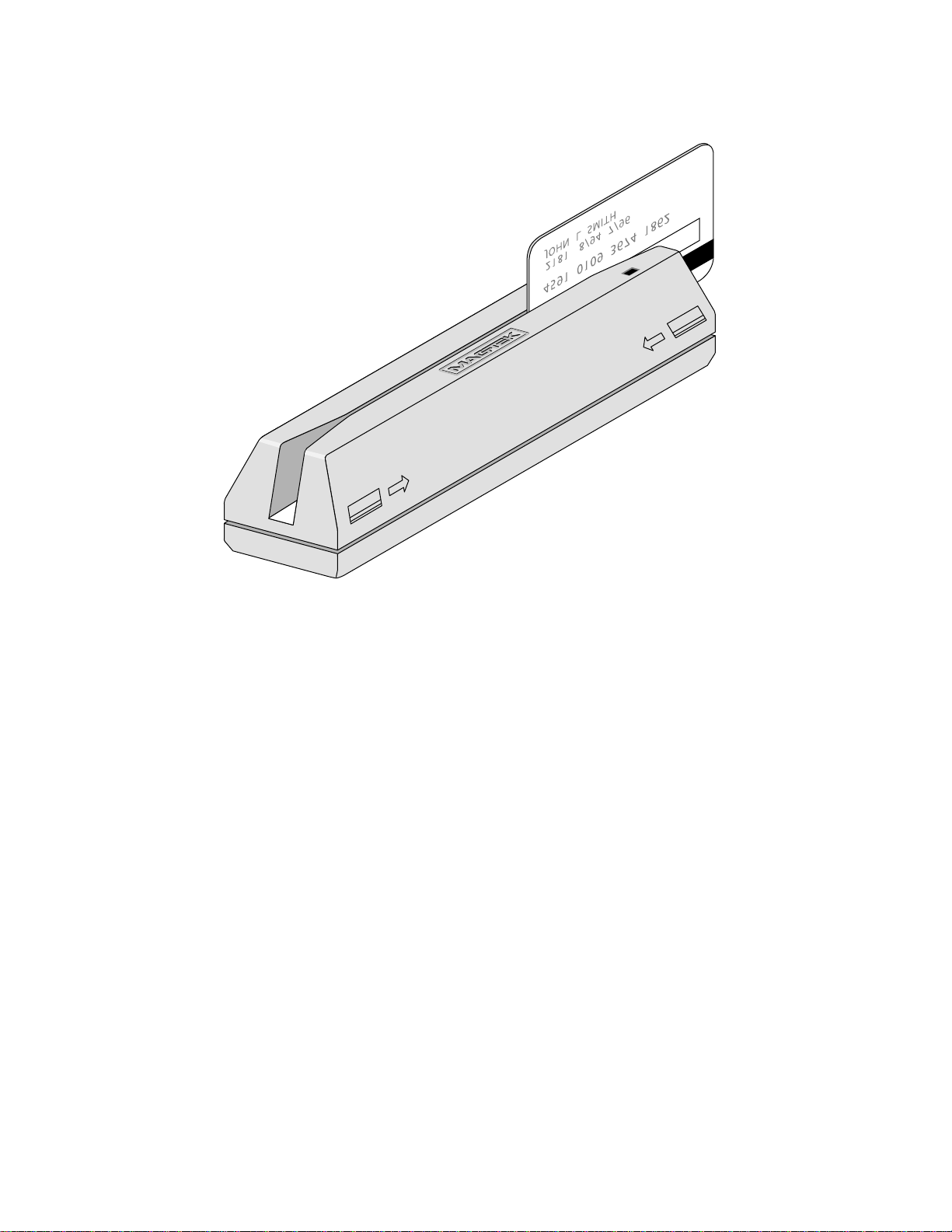
Figure 1-1. RS-232 Swipe Reader
vi
Page 7

SECTION 1. FEATURES AND SPECIFICATIONS
The Model MT-211232, 3-Track, RS-232 Swipe Reader, is a compact magnetic stripe card
reader which conforms to standards of the following: ANSI (American National Standards
Institute), ISO (International Standards Organization), CDL (California Drivers License), and
AAMVA (American Association of Motor Vehicle Administrators).
The Reader is compatible with the PC AT/PS2 series of personal computers or any computer
with an RS-232 interface. A card is read by sliding it, stripe down and facing the LED side,
through the slot either forward or backward.
A block of eight switches selects the RS-232 communication parameters and the user protocol.
A two-color LED (Light Emitting Diode) indicator on the Reader panel and an audible alarm
inside the Reader provide the operator with continuous status of the Reader operations.
Part numbers for the Readers and a brief description of the differences are as follows:
21088045 Normal power adaptor - 115V, 60Hz, output 9VDC.
This supply has the correct plug for MT211232.
21088047 Power adaptor 220V, 50Hz, output 9VDC (P/N64300065) has two
round prongs, 4 mm in diameter and 17.5 mm apart (center to
center) per standard TUV/VDE. This supply has the correct plug
for MT211232.
21088048 No power supply
FEATURES
Major features of the Swipe Reader are as follows:
• Hardware Compatible with AT/PS2 or any computer or terminal with an RS-232 interface
• Software Compatible with ProComm (Customer provided - Windows version 3.0 or higher,
or DOS version 2.0 or higher; or other RS-232 communications programs may be used)
• Switch Selectable Baud Rate
• Switch Selectable Parity
• Switch Selectable Buffered or Unbuffered Mode
• On/Off switch for STX (Start of Text) and ETX (End of Text), framing message characters
1
Page 8

RS-232 Swipe Reader, 3-Track
• On/Off switch for SS (Start Sentinel) and ES (End Sentinel) framing track characters
• On/Off switch for CR (Carriage Return)
• Two way card reading
• Generates an audible beep when reading is successful and three beeps when unsuccessful
• Reads encoded data that meets ANSI/ISO/CDL/AAMVA standards
• External power supply
• Power Supply Adaptor, 115VAC input, Part Number 64300021, included
• ASCII Message Format
• Two-color LED; green for ready to read, red for error
MODES OF OPERATION
The two modes of operation are unbuffered and buffered. The switch setting to select the mode
is shown in Section 3. The Reader must be turned off when selecting either the buffered or
unbuffered mode.
Unbuffered Mode
In the unbuffered operating mode, data from the Reader is automatically sent to the host without
being requested. When a card is passed through the Reader, data is transmitted immediately and
is not retained.
The Reader does not need to receive commands from the host in order to transmit data.
However, the Reader does respond to an Inquiry Command by sending an ASCII “R”. (See Host
to Reader Commands and Reader to Host Commands in Section 3.) An example of the use of an
Inquiry Command would be to determine whether the power is on at a remote MT-211232.
Buffered Mode
In the buffered operating mode, the Reader stores the card data in a memory buffer and does not
transmit any data to the host until an Inquiry Command is received. Upon receipt of an Inquiry
Command, data is transmitted to the host. If no data is present in the memory buffer, only the
2
Page 9

Section 1. Features and Specifications
ASCII “R” will be transmitted. Data is not cleared from the memory buffer until a Release
Command is received. The Reader cannot read another card until the buffer is cleared, and the
green LED is lit.
CONFIGURATION
The Reader, LED Indicator, RJ11 Jack, pin numbers for the 9-pin connector, and the Power
Adaptor are shown in Figure 1-2. This Reader does not support PINPads.
Figure 1-2. Reader Cable and Power Adaptor
RELATED DOCUMENTS
MagTek 99875125 The MagTek Device Drivers for Windows, Part Number
30037385, or 99510030 (Windows 9x/ME), or
99510031(Windows NT), 99510032 (Windows 2000/XP), or may
be used with the Port Powered Insertion Reader. The title of the
manual is MagTek Device Drivers For Windows Programming
Reference Manual.
ISO 7810 ID Cards – Physical Characteristics
ISO 7811-2 ID Cards – Recording Technique – Low Coercivity
ISO 7811-6 ID Cards – Recording Technique – High Coercivity
Available from ANSI; phone 212-642-4900; www.ansi.org
3
Page 10

RS-232 Swipe Reader, 3-Track
Pin numbers and signal descriptions for the 9-pin cable shown in the illustration are listed in
Table 1-1.
Table 1-1. 9-Pin Connector Pin Numbers
Pin
Number
1
2 TXD Transmitted Data, RS-232 Signal. Transmits data from the
3 RXD Received Data, RS-232 Signal. Receives data from the Host
4* DTR Data Terminal Ready, RS-232 Signal. Transmits a signal to
5 GND Ground
6* DSR Data Set Ready, RS-232 Signal. Receives a signal from the
7* RTS Request to Send, RS-232 Signal. Sends a signal to the Host
8* CTS Clear to Sent, RS-232 Signal. Receives a signal from the
9
*The control signals on pins 4 and 6 and 7 and 8 are not supported in this unit and are wired
as indicated, on the PCB Connector JP1.
Signal
Description
Reader to the Host.
to the Reader.
the Host to indicate that the Reader is active, i.e., power is on.
Host to indicate that the Host is active, i.e., power is on.
to indicate that the Reader is ready to transmit data.
Host that allows data to be transmitted.
OPTIONS
The optional cables and adaptor for the Reader are as follows:
Title Description Part Number
RS232 Y Cable 4-Pin RJ11 to 9-Pin DB Female 6 ft. 21083581
RS232 Y Cable 4-Pin RJ11 to 25-Pin DB Female 6 ft. 21083582
RS232 Y Cable 4-Pin RJ11 to 25-Pin DB Male 6 ft. 21083583
Adaptor 9-pin DE Male to 25-pin DB Female, 1.8 in. 78200018
The cables are shown in Figure 1-3. The 9-pin connector is shown on top and the 25-pin
connectors are shown below. The installation is shown in Section 2.
4
Page 11

Section 1. Features and Specifications
Figure 1-3. Cable Options
Pin numbers for the RJ11 9-pin connector (P/N 21083581) are shown in Table 1-2. This
terminal uses Com Port 1.
Table 1-2. Optional 9-Pin Cable
Connector Wire
4-Pin RJ11 Plug and Signal 9-Pin DB Female and Signal
1 RXD 3 TXD
2 GND 5 GND
3 TXD 2 RXD
7 RTS
8 CTS
1 CD
4 DTR
6 DSR
*The control signals on pins 7 and 8 and 1, 4, and 6 are not supported in this unit
and are wired as indicated.
Pin numbers for the RJ11 25-pin female connector (P/N 21083582) are shown in Table 1-3. This
terminal uses Com Port 2 or PS2.
5
Page 12
RS-232 Swipe Reader, 3-Track
Table 1-3. Optional 25-Pin Female Cable
Connector Wire
4-Pin RJ11 Plug and Signal 25-Pin DB Female and Signal
1 RXD 2 TXD
2 GND 7 GND
3 TXD 3 RXD
4 RTS*
5 CTS*
6 DSR*
20 DTR*
8 CD*
*The control signals on pins 4 and 5 and 6, 20, and 8 are not supported in this unit
and are wired as indicated.
Pin numbers for the RJ11 25-pin male cable (P/N 21083583) are shown in Table 1-4. This is for
a dumb terminal (for example, a WYSE terminal).
Table 1-4. Optional 25-Pin Male Cable
Connector Wire
4-Pin RJ11 Plug and Signal 25-Pin DB Male and Signal
1 RXD 2 TXD
2 GND 7 GND
3 TXD 3 RXD
4 RTS*
5 CTS*
6 DSR*
20 DTR*
8 CD*
*The control signals on pins 4 and 5 and 6, 20, and 8 are not supported in this unit
and are wired as indicated.
6
Page 13

Section 1. Features and Specifications
Figure 1-4 shows the Reader, cable and optional adaptor. Pin numbers and signals are listed in
Table 1-5.
LED Indicator
1
6
9 Pin Connector
9 Pin Connector
5
9
9 To 25 Pin
Adaptor
13
25
Figure 1-4. Reader, Cable, and Optional Adapter
Table 1-5. 9-Pin Connector and 25-Pin Adaptor
DE 9-Pin Connector 25-Pin Adaptor Signal
1 8 NC
2 3 RXD
3 2 TXD
4 20 DTR*
5 7 GND
6 6 DSR*
7 4 RTS*
8 5 CTS*
9 22 NC
*The control signals on pins 4, 5, 6, and 20 are not supported in this
unit and are wired as indicated.
1
14
7
Page 14

RS-232 Swipe Reader, 3-Track
SPECIFICATIONS
Table 1-6 lists the specifications for the MT211232, RS-232 Swipe Reader, 3 Track.
Figure 1-5 shows the dimensions.
Table 1-6. Specifications
OPERATING
Reference Standards ANSI/ISO/CDL/AAMVA
Power Input 9 Volt, 300 mA DC Adaptor (Included), 115 VAC, 60 Hz
Power Consumption 115 mA at 9 VDC
Recording Method Two-frequency coherent phase (F2F)
Message Format ASCII
Card Speed 3 to 50 IPS at 75 BPI or 210 BPI (7.6 to 127 cms/sec)
MTBF Electronics: 125,000 hours. Head: 1,000,000 passes
Flammability Meets UL 94V-0
MECHANICAL
Dimensions Length 6 1/2”, Width 1 3/4”, Height 1 5/8”
Weight: Reader 7 oz. Adaptor: 11oz.
Cable length 6’ (1.82 meters) Maximum length is 50’ (15 meters)
Connector 9 pin D female, (May require an optional 25-pin adaptor), P/N 78200018
ENVIRONMENTAL
Temperature
Operating 32
Storage -22
Humidity
Operating 10% to 90% noncondensing
Storage Up to 100% noncondensing
Altitude
Operating 0-10,000 ft. (0-3,048 m.)
Storage 0-50,000 ft. (0-15,240 m.)
o
F to 131 oF (0 oC to 55 oC)
o
F to 158 oF (-30 oC to 70 oC)
8
Page 15

Section 1. Features and Specifications
Figure 1-5. Dimensions
9
Page 16

RS-232 Swipe Reader, 3-Track
10
Page 17

SECTION 2. INSTALLATION
The hardware installation consists of plugging in the appropriate cables for the selected
configuration, setting the switches, and installing the required software.
HARDWARE INSTALLATION
The Reader is connected to a host computer and terminal as indicated in Figure 2-1. The RJ11
cable shown in the illustration is optional and may be either a 9- or 25-pin connection (see
Section 1).
Figure 2-1. Reader Connections
11
Page 18

RS-232 Swipe Reader, 3-Track
Install the Reader as follows:
Caution
Ensure power is off to the computer until all connections are
made. Ensure the power adaptor is not connected until the other
connections to the Reader are made.
1. Connect the serial cable from the Reader to the PC serial port. A 9-pin to 25-pin adaptor
may be required.
2. Connect the power plug to the Reader jack, and plug the adaptor into a 115 VAC wall
socket. The green LED on the Reader should light and the alarm should beep once. If it
does not, recheck the cable connections and if necessary, notify technical personnel, and
if necessary, call MagTek Customer Assistance at 1-888-624-8350.
3. Turn on power to the computer.
4. Open ProComm, either the Windows or DOS version. Other communications programs
may be used.
5. At the bottom of the ProComm screen, the parameters are given. Ensure the switch
settings match the values on the screen. The default values of the switches are listed in
Table 2-3. If PC Com Port 2 is used for the Reader, ensure the screen shows “direct
connect-Com 1 or 2”. The default value of the baud rate is 9600, and the default parity,
(which should show on the screen as O-7-1) is Odd parity, 7 bit, 1 stop bit. If the
switches are not set to the default values, ensure the ProComm screen reflects the values
for the settings.
6. Use a known good, 3-track, magnetic striped, card, and swipe it through the reader.
7. If the Reader beeps once and the LED comes on green, it is working and properly
connected; proceed to the next step. If the Reader beeps three times and the LED comes
on red or orange momentarily, there is an error; the card was swiped incorrectly, or the
unit is not working, or is not properly connected. Check the cabling, reset the unit by
disconnecting and connecting the power plug, try another card, and call technical support
if there is still an error, and if necessary, call MagTek Customer Assistance at 1-888-624-
8350.
8. The Reader will respond with a green LED and one beep if only 1 track on the card is
good. One or more bad tracks will be shown on the screen. Check the screen for each of
the three tracks; Track 1 begins with “%”, Track 2 begins with “;” and Track 3 begins
with “+” or sometimes with “!”.
12
Page 19

Section 2. Installation
9. If 3 tracks were encoded and none of the tracks are good, the red LED will light
momentarily, three beeps will sound, and an “E” or “EEE” will appear on the screen.
Note
If the card is inserted backwards (mag stripe on the opposite side
of the LED) or is not encoded, the LED will not go out and there
will be no audio alarm.
10. If there were no errors during installation, test the red light and alarm by partially
inserting the card approximately one inch, stop, then remove the card. The Red (or
orange LED) should light momentarily and there should be three beeps.
11. Swipe another known good card. If the Reader responds with the green LED and one
beep, the unit is ready for operation.
Switch Settings
The switch block is located on the bottom of the Reader. Figure 2-2 shows the switches and the
ON/OFF positions. Ensure power is off before setting the switches to ensure the switch settings
are properly loaded.
Figure 2-2. Switches
Switches 1 and 2: Table 2-1 shows the switch settings for the baud rate.
Switches 3 and 4: Table 2-2 shows the parity settings, and the other switches are described
below.
13
Page 20

RS-232 Swipe Reader, 3-Track
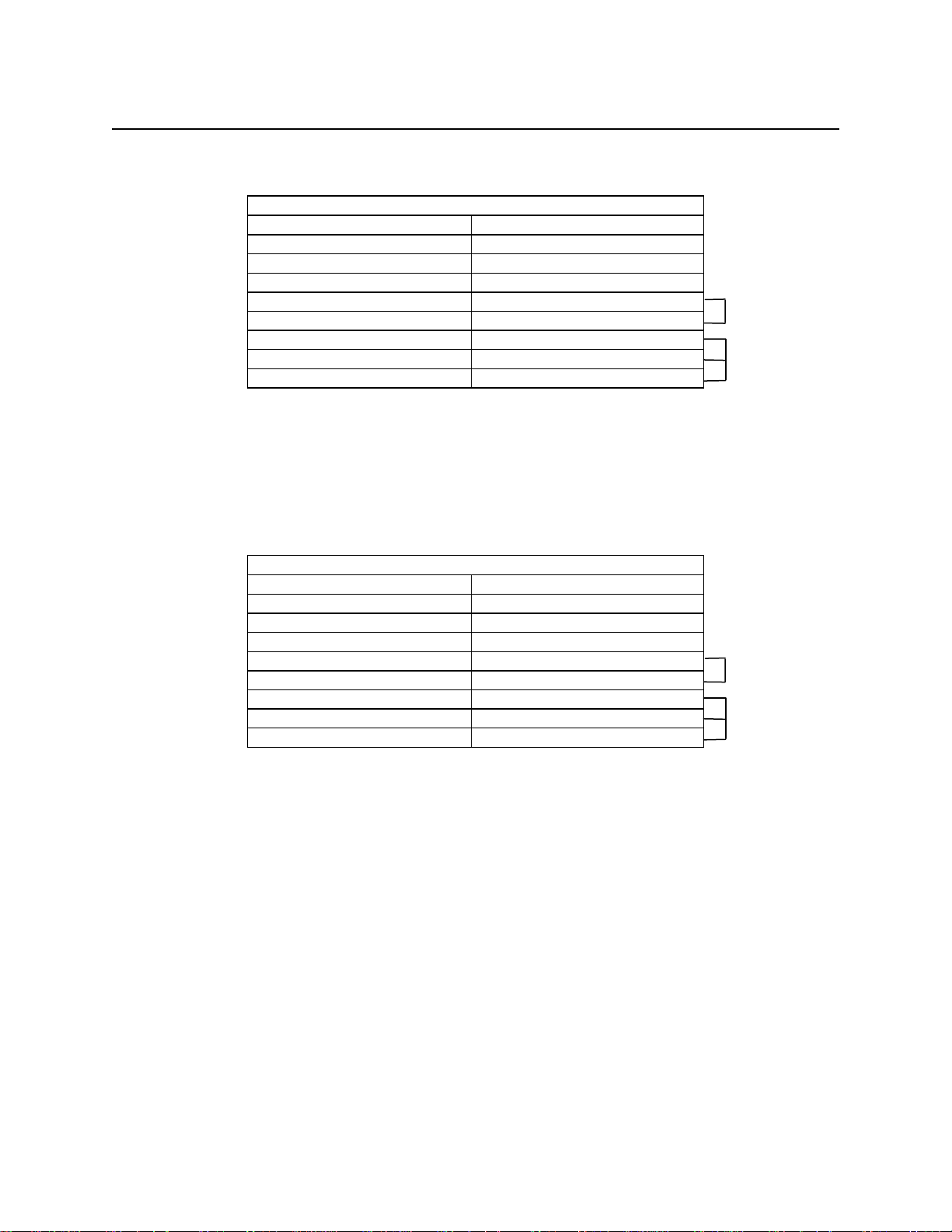
Table 2-1. Baud Rate Settings
Baud Rate SW1 SW2
2400 OFF OFF
4800 ON OFF
9600 OFF ON
19200 ON ON
Table 2-2. Parity Settings
Parity SW3 SW4 Description
ODD OFF OFF Parity Enabled
MARK ON OFF Parity Disabled
EVEN OFF ON Parity Enabled
SPACE ON ON Parity Disabled
Switch 5: This is an option switch that sends Start of Text (STX) and End of Text (ETX)
framing characters when set to the ON position. If framing characters are not desired, set
Switch 5 to the OFF position.
Switch 6: This is an option switch that sends one Carriage Return (CR) after the last
track when set to the ON position. If this control character is not desired, set Switch 6 to
the OFF position.
Switch 7: This is an option switch that sends the Start Sentinel (SS) and the End Sentinel
(ES) framing characters when set to the ON position. If the framing characters are not
desired, set Switch 7 to the OFF position.
Switch 8: When Switch 8 is OFF, the unit is in the unbuffered mode, and data is
automatically sent to the PC without being requested. When ON, the unit is in the
buffered mode, and data is not sent to the PC until the Reader receives an Inquiry
Command.
The switches are preset at the factory as shown in Table 2-3.
14
Table 2-3. Factory Settings
Switch Setting Description
SW1 OFF
SW2 ON
SW3 OFF
SW4 OFF
SW5 ON Send STX and ETX
SW6 ON Send CR
SW7 ON Send SS and ES
SW8 OFF Unbuffered Mode
Baud Rate 9600
1 Start Bit, 7 Data Bits
Odd Parity, 1 Stop Bit
Page 21

SECTION 3. OPERATION
Included in this section are Indicators, Card Read, Reader to Host Message Format, Host to
Reader Commands, a timing diagram of transmission, and the top assembly drawing of the
Reader.
INDICATORS
A two-color LED indicator on the panel gives the operator the status of the Reader. An audio
alarm inside the Reader provides a beep for the operator.
Green LED
The green LED is the ready indicator which lights when the Reader is ready to read a magnetic
stripe or after a card was read without error.
Red LED
The red LED (or orange LED) lights when an error occurs after the card is swiped. This
indicates that the card did not read a track(s) correctly. An “E” will be displayed in place of the
card data for each track that had an error. If the card is swiped with the stripe facing away from
LED side, or was not encoded, nothing will occur, no LED or alarm. The LED is out when the
Reader is processing date or when no power is applied.
Audio Alarm
The Alarm will beep once if the installation is correct or when a magnetic card is read
successfully and will beep three times if the installation is incorrect or when a read error is
detected.
CARD READ
A card may be swiped through the Reader slot when the green LED is lit. The magstripe must
face toward the front (the side with the LED and arrows) and may be swiped from either
direction.
The green LED will go out momentarily when a properly encoded card is swiped through the
Reader. The alarm will beep once and the green LED will reappear when all valid information is
transmitted to the computer and the Reader is ready to accept another card.
The red LED lights momentarily and the alarm beeps three times when an error occurs during a
card read. If the unit was installed correctly, the error will probably be caused by not swiping
the card correctly or the problem may be with the encoding on the card.
15
Page 22

RS-232 Swipe Reader, 3-Track
If the Reader does not respond as described above, make a note of the prompts or error messages
on the display and status of the LED on the Reader. Then call MagTek Customer Assistance at
1-888-624-8350.
READER TO HOST MESSAGE FORMAT
Figure 3-1 shows the format in which data is transmitted after a card with a single track is read
successfully. Track data is sent in the following order: SS, Track Data, ES.
STX> SS CARD DATA ES <CR> <ETX>
End of Text Character
(03 Hex) Optional.
Set SW5 to ON
Carriage Return Character (OD Hex)
Optional. Set SW6 to ON.
End Sentinel Character
(ASCII “?”) Set SW7 to ON.
Card Data in ASCII Track Order
Start Sentinel Character. Set SW7 to ON
(ASCII “%” for ISO Track 1)
(ASCII “;” for ISO Track 2)
(*ASCII “+” for ISO Track 3)
Start of Text Character (02 Hex)
*“+” = Other symbols may be used for Track 3, e.g., “!” , “;”, or “B”.
Figure 3-1. Host Message Format for a Single Track
Figure 3-2 shows the format in which data is transmitted after a card with all three tracks is read
successfully and switches 5, 6, and 7 are on. The output is as follows:
STX SS
TK 1
CD
TK 1
ES
TK 1
SS
TK 2
CD
TK2
ES
TK2
SS
TK 3
CD
TK 3
ES
TK 3
CR ETX
Figure 3-2. Host Message Format for Three Tracks
Where:
STX = Start of Text Character (02 Hex)
SS = Start Sentinel (See above for ASCII symbol for track)
CD = Card Data (Card Data in ASCII Track Order)
ES = End Sentinel (See above for ASCII symbol for track)
CR = Carriage Return (OD Hex)
ETX = End of Text Character (03 Hex)
16
Page 23

Section 3. Operation
HOST TO READER COMMANDS
All commands transmitted from the host to the Reader must be preceded by an ASCII “Escape”
<ESC> character. Characters that precede or follow the command sequence will not affect the
Reader’s command interpretation. All ASCII characters must be transmitted in UPPER CASE
(for example, ASCII “I” and “R”).
Buffer Mode Commands
Commands used in the buffer mode are as follows:
Switch 8 Command Description
ON <ESC> “I “ Inquiry Command: In the buffered mode, requests the Reader
to Transmit data, or “E” for error, or “R” for empty buffer. In
the unbuffered mode transmits an ASCII “R”.
ON <ESC> “R” Release Command: In the buffered mode, requests the Reader
to clear the memory buffer of any data present. This command
has no effect in the unbuffered mode.
TIMING
Transmission timing is shown in Figure 3-3. Each ASCII character is transmitted with 1 start
bit, 7 data bits, 1 parity bit, and 1 stop bit. Logic levels conform to standard RS-232 levels; logic
levels are “true” or “1” if the level is low. The levels are quiescently low.
Figure 3-3. Transmission Timing
TOP ASSEMBLY DRAWING
The top assembly drawing is shown in Figure 3-4.
17
Page 24

RS-232 Swipe Reader, 3-Track
18
Figure 3-4. Top Assembly Drawing
 Loading...