

Page 1

MINIWEDGE
TM
SWIPE READER
TECHNICAL REFERENCE MANUAL
Manual Part Number: 99875123 Rev 11
APRIL 2004
REGISTERED TO ISO 9001:2000
1710 Apollo Court
Seal Beach, CA 90740
Phone: (562) 546-6400
FAX: (562) 546-6301
Technical Support: (651) 415-6800
www.magtek.com
Page 2

Copyright© 1998 - 2005
MagTek®, Inc.
Printed in the United States of America
Information in this document is subject to change without notice. No part of this document may be
reproduced or transmitted in any form or by any means, electronic or mechanical, for any purpose,
without the express written permission of MagTek, Inc.
MagTek and MiniWedge are registered trademarks of MagTek, Inc.
REVISIONS
Rev Number Date Notes
1 30 Nov 98 Initial Release
2 30 Nov 98 No change from initial release. Revised to include ECN
4754, which was included in Revision 1.
3 17 Mar 99 Sec 1: Editorial Changes; Sec 2: Editorial Changes;
Sec 3: Editorial Changes, added Windows Drivers
application, changed Parameter Address List, Moved
Response Codes and Timing; Appendix A: Added
Character Timing Diagram.
4 12 May 99 Sec 1: Added two P/Ns; Sec 2: Modified note under
Cabling, Table 2-1 changed title, Sect 3: Editorial, added
Hardware Track Mapping and examples.
5 17 Sep 99 Sec 1: Added note for foreign keyboards; Sec 2:
changed Device-Specific Operation Table and
Parameter Address List; Sec 3:
Added Parameter P080 and Shift Flag.
6 21 Sep 00 Sec 1: Added 35 language configurations under Part
Numbers; under features, added Auto-detect; Table 1-1,
Specifications, added track formats; under Dimension
and Length changed to 3.94" (100.0 mm); weight
changed to 5.8 oz; Converted symbols to Metric System
[SI]. Sec 2: added error and LED descriptions.
Sec 3: Corrected Table 3-1, and 3-2; Added responses
to examples.
7 8 Jun 01 Front Matter: Updated Agency Approval page to include
Class B and UL approvals; Sec 1: added P/N 21080244;
Sec 3: to Device Specific Operation Table added Mag
Wedge and DOS Mode. Added new section, Index.
8 5 Apr 02 Sec 1, 2, 3: Added index entries. Sec 2: changed Fig 2-
2, 2-3, and added Fig 2-4 to reflect new cable.
9 22 Aug 02 Sec 1: added P/N 21080246 to Table, Trk 1,2, pearl
white (no cover); Sec 3: To Table 3-3 added 02E, Start
Sentinel char for Trk 1, to P014 added BAT AA, Basic
Assurance Test/twice, to P080 added S1, Keyboard uses
shift lock; Index: added LED entries.
10 13 May 03 Front Matter: added ISO line to logo, changed Tech
Support phone number, added new warranty statement.
11 19 Apr 04 Section 1: Removed P/N table and added configuration
table. Editorial throughout.
ii
Page 3

LIMITED WARRANTY
MagTek warrants that the products sold to Reseller pursuant to this Agreement will perform in accordance with
MagTek’s published specifications. This warranty shall be provided only for a period of one year from the date
of the shipment of the product from MagTek (the “Warranty Period”). This warranty shall apply only to the
original purchaser unless the buyer is authorized by MagTek to resell the products, in which event, this warranty
shall apply only to the first repurchase.
During the Warranty Period, should this product fail to conform to MagTek’s specifications, MagTek will, at its
option, repair or replace this product at no additional charge except as set forth below. Repair parts and
replacement products will be furnished on an exchange basis and will be either reconditioned or new. All replaced
parts and products become the property of MagTek. This limited warranty does not include service to repair
damage to the product resulting from accident, disaster, unreasonable use, misuse, abuse, customer’s negligence,
Reseller’s negligence, or non-MagTek modification of the product. MagTek reserves the right to examine the
alleged defective goods to determine whether the warranty is applicable.
Without limiting the generality of the foregoing, MagTek specifically disclaims any liability or warranty for
goods resold in other than MagTek’s original packages, and for goods modified, altered, or treated by customers.
Service may be obtained by delivering the product during the warranty period to MagTek (1710 Apollo Court,
Seal Beach, CA 90740). If this product is delivered by mail or by an equivalent shipping carrier, the customer
agrees to insure the product or assume the risk of loss or damage in transit, to prepay shipping charges to the
warranty service location and to use the original shipping container or equivalent. MagTek will return the product,
prepaid, via a three (3) day shipping service. A Return Material Authorization (RMA) number must accompany
all returns.
MAGTEK MAKES NO OTHER WARRANTY, EXPRESS OR IMPLIED, AND MAGTEK DISCLAIMS ANY
WARRANTY OF ANY OTHER KIND, INCLUDING ANY WARRANTY OF MERCHANTABILITY OR
FITNESS FOR A PARTICULAR PURPOSE.
EACH PURCHASER UNDERSTANDS THAT THE MAGTEK PRODUCT IS OFFERED AS IS. IF THIS
PRODUCT DOES NOT CONFORM TO MAGTEK’S SPECIFICATIONS, THE SOLE REMEDY SHALL BE
REPAIR OR REPLACEMENT AS PROVIDED ABOVE. MAGTEK’S LIABILITY, IF ANY, TO RESELLER
OR TO RESELLER’S CUSTOMERS, SHALL IN NO EVENT EXCEED THE TOTAL AMOUNT PAID TO
MAGTEK BY RESELLER UNDER THIS AGREEMENT. IN NO EVENT WILL MAGTEK BE LIABLE TO
THE RESELLER OR THE RESELLER’S CUSTOMER FOR ANY DAMAGES, INCLUDING ANY LOST
PROFITS, LOST SAVINGS OR OTHER INCIDENTAL OR CONSEQUENTIAL DAMAGES ARISING OUT
OF THE USE OF OR INABILITY TO USE SUCH PRODUCT, EVEN IF MAGTEK HAS BEEN ADVISED OF
THE POSSIBILITY OF SUCH DAMAGES, OR FOR ANY CLAIM BY ANY OTHER PARTY.
LIMITATION ON LIABILITY
EXCEPT AS PROVIDED IN THE SECTIONS RELATING TO MAGTEK’S LIMITED WARRANTY,
MAGTEK’S LIABILITY UNDER THIS AGREEMENT IS LIMITED TO THE CONTRACT PRICE OF THE
PRODUCTS.
MAGTEK MAKES NO OTHER WARRANTIES WITH RESPECT TO THE PRODUCTS, EXPRESSED OR
IMPLIED, EXCEPT AS MAY BE STATED IN THIS AGREEMENT, AND MAGTEK DISCLAIMS ANY
IMPLIED WARRANTY, INCLUDING WITHOUT LIMITATION ANY IMPLIED WARRANTY OF
MERCHANTABILITY OR FITNESS FOR A PARTICULAR PURPOSE.
MAGTEK SHALL NOT BE LIABLE FOR CONTINGENT, INCIDENTAL, OR CONSEQUENTIAL
DAMAGES TO PERSONS OR PROPERTY. MAGTEK FURTHER LIMITS ITS LIABILITY OF ANY KIND
WITH RESPECT TO THE PRODUCTS, INCLUDING ANY NEGLIGENCE ON ITS PART, TO THE
CONTRACT PRICE FOR THE GOODS.
MAGTEK’S SOLE LIABILITY AND BUYER’S EXCLUSIVE REMEDIES ARE STATED IN THIS SECTION
AND IN THE SECTION RELATING TO MAGTEK’S LIMITED WARRANTY.
iii
Page 4

FCC WARNING STATEMENT
This equipment has been tested and found to comply with the limits for Class B digital device, pursuant to Part 15
of FCC Rules. These limits are designed to provide reasonable protection against harmful interference when the
equipment is operated in a residential environment. This equipment generates, uses, and can radiate radio
frequency energy and, if not installed and used in accordance with the instruction manual, may cause harmful
interference to radio communications. However, there is no guarantee that interference will not occur in a
particular installation.
FCC COMPLIANCE STATEMENT
This device complies with Part 15 of the FCC Rules. Operation of this device is subject to the following two
conditions: (1) This device may not cause harmful interference; and (2) this device must accept any interference
received, including interference that may cause undesired operation.
CANADIAN DOC STATEMENT
This digital apparatus does not exceed the Class B limits for radio noise for digital apparatus set out in the Radio
Interference Regulations of the Canadian Department of Communications.
Le présent appareil numérique n’émet pas de bruits radioélectriques dépassant les limites applicables aux
appareils numériques de las classe B prescrites dans le Réglement sur le brouillage radioélectrique édicté par les
ministère des Communications du Canada.
CE STANDARDS
Testing for compliance to CE requirements was performed by an independent laboratory. This equipment has
been tested and demonstrated compliance to current European Union Directive 89/336/EEC for Class B
disturbance level.
UL/CSA
This product is recognized per Underwriter Laboratories and Canadian Underwriter Laboratories 1950.
iv
Page 5

TABLE OF CONTENTS
SECTION 1. FEATURES AND SPECIFICATIONS.....................................................................................1
CONFIGURATIONS .................................................................................................................................1
FEATURES...............................................................................................................................................1
RELATED DOCUMENTS.........................................................................................................................2
SPECIFICATIONS....................................................................................................................................2
SECTION 2. INSTALLATION......................................................................................................................5
HARDWARE INSTALLATION ..................................................................................................................5
Mounting ................................................................................................................................................5
Cabling...................................................................................................................................................6
CARD READING.......................................................................................................................................9
DATA ERROR DETECTED......................................................................................................................9
SECTION 3. OPERATION.........................................................................................................................11
COMMAND CODES FROM THE PC TO THE READER.......................................................................11
MESSAGE FORMAT..............................................................................................................................11
DEVICE-SPECIFIC OPERATION...........................................................................................................12
RESPONSE CODES AND TIMING........................................................................................................13
MINIWEDGE COMMANDS AND RESPONSES....................................................................................13
MAGWEDGE COMPATIBILITY..............................................................................................................15
PARAMETER ADDRESS LIST...............................................................................................................16
P001 Parameter Table ID #...............................................................................................................17
P013 Track/ID Enable........................................................................................................................17
P014 Track Data Send Flags.............................................................................................................17
P022 Terminating Char......................................................................................................................18
P02A Hardware Track Mapping.........................................................................................................18
P080 KB Flag.......................................................................................................................................19
Shift Flag..............................................................................................................................................19
Card Data Format ................................................................................................................................20
Parameter Modifications ......................................................................................................................20
Examples of Command Sequences.....................................................................................................20
DATA ERROR CONDITIONS.................................................................................................................21
APPENDIX A. CHARACTER TIMING.......................................................................................................23
INDEX..........................................................................................................................................................25
FIGURES
Figure 1-1. MiniWedge Reader...................................................................................................................vi
Figure 1-2. Dimensions................................................................................................................................3
Figure 2-1. Mounting Hole Dimensions For Surface....................................................................................6
Figure 2-2. AT-style Configuration – Old Style Cable..................................................................................7
Figure 2-3. PS/2-style Configuration – Old Style Cable...............................................................................7
Figure 2-4. PS/2-style Configuration – New Style Cable.............................................................................8
Figure A-1. Character Timing Diagram......................................................................................................23
TABLES
Table 1-1. Specifications..............................................................................................................................2
Table 2-1. Six-pin Mini DIN connector .........................................................................................................8
Table 2-2. Five-pin DIN Connector ..............................................................................................................8
Table 3-1. Device Specific Operation.........................................................................................................12
Table 3-2. Commands and Responses......................................................................................................14
Table 3-3. Parameter Address List ............................................................................................................16
v
Page 6

Figure 1-1. MiniWedge Reader
vi
Page 7

SECTION 1. FEATURES AND SPECIFICATIONS
The MiniWedgeTM Swipe Reader connects between a PC and its keyboard. The Reader looks
transparent to both the keyboard and the PC until a card is read. When a card is read, the Reader
disables the keyboard and sends card data using the same scan codes used by the keyboard. The
PC cannot distinguish between data from the keyboard and data from the Reader. MiniWedge
Readers can connect to PS/2 or AT type PCs.
The PC keyboard supplies power to the MiniWedge Reader. The Reader can be configured to
send card data with or without start sentinel, end sentinel, and carriage returns. The MiniWedge
Reader also recognizes commands from the PC to enable or disable the keyboard or card reading.
When powered up, all devices are active.
CONFIGURATIONS
Part numbers for the MiniWedge Swipe Reader are 21080201 through 21080247. For
information on individual models, contact MagTek sales.
FEATURES
Major features of the Swipe Reader are as follows:
• Powered through the keyboard interface – no external power supply required
• Hardware Compatible with PC or any computer or terminal with PC keyboard interface
• Bidirectional card reading
• Reads encoded data that meets the standards of ANSI (American National Standards
Institute); ISO (International Standards Organization); CA DL/ID (California Driver License)
AAMVA (American Association of Motor Vehicle Administrators).
• Auto-detects track encoding format. Can read 7-bit, 210 bpi data on all three tracks.
• Two-color LED for status
• Small Footprint
1
Page 8

MiniWedge Swipe Reader
RELATED DOCUMENTS
MagTek Device Drivers For Windows, Programming Reference Manual, P/N 99875125.
SPECIFICATIONS
Table 1-1. Specifications
OPERATING
Reference Standards ISO/ANSI/ CDL/ AAMVA
Recording Method Two-frequency coherent phase (F2F)
Message Format Scan Code
Card Speed 3 to 50 IPS
Track Format Reads 75-210 bpi on all 3 tracks
MTBF Electronics: 125,000 hours. Head: 1,000,000 passes
ELECTRICAL
Power Input From PC: 5VDC; power supplied by keyboard interface
Current 20 mA max
MECHANICAL
Dimensions Length 3.94” (100.0 mm)
Width 1.28” (32.5 mm)
Height 1.23” (31.3 mm)
Weight, Reader only 5.8 oz. (165 gr.)
Reader with Cable 6.5 oz. (184 gr.)
Cable length 6 Ft. (1.8 m)
Connectors 6-pin Mini Din and 5-pin Din; includes adapter cable
ENVIRONMENTAL
Temperature
Operating 32
Storage -22oF to 158oF (-30 oC to 70 oC)
Humidity
Operating 10% to 90% noncondensing
Storage Up to 100% noncondensing
Altitude
Operating 0-10,000 ft. (0-3048 m.)
Storage 0-50,000 ft. (0-15240m.)
o
F to 131 oF (0 oC to 55 oC)
2
Page 9

Section 1. Features and Specifications
Figure 1-2. Dimensions
3
Page 10

MiniWedge Swipe Reader
4
Page 11

SECTION 2. INSTALLATION
The MiniWedge Reader cable is a Y cable that permits the MiniWedge Reader to be installed
between the PC and the PC keyboard. There is also an adapter cable that is used to adapt various
connector configurations to interface with the Reader. These configurations are described and
illustrated below.
HARDWARE INSTALLATION
To install the MiniWedge Reader proceed as follow:
Mounting
1. The Reader can be mounted on a surface in three ways:
• By two screws through the surface attached to the bottom of the unit and running the
cable on the top of the surface;
• By two screws through the surface attached to the bottom of the unit and by drilling a
hole in the surface for the cable and running the cable through the hole;
• By attaching the unit to the surface with Velcro or Dual Lock mounting pads and
running the cable on the top of the surface.
Note
The two mounting inserts are 3 mm diameter; 0.5 mm pitch; 6.4
mm deep. The length of the screws used depends on the mounting
surface thickness and the thickness of washers (if used).
The mounting dimensions are shown in Figure 2-1. Determine the method of mounting
required.
2. Ensure the Reader is positioned on a flat, accessible surface with at least 4 inches
clearance on either end for room to swipe a card. Orient the Reader so the side with the
LED is facing the direction of intended use.
If Velcro or Dual Lock mounting pads are to be used, clean the area that the Reader will
be mounted on with isopropyl alcohol. Remove the adhesive protective cover on the
pads, and position the Reader and push down firmly.
3. Mount the Reader.
5
Page 12

MiniWedge Swipe Reader
Figure 2-1. Mounting Hole Dimensions For Surface
Cabling
1. Power down the PC.
2. Connect the cables as indicated in Figure 2-2, Figure 2-3, or Figure 2-4. One end of the Y
cable plugs into the PC. The other end plugs into the keyboard; however, if a keyboard is
not required, leave this end unconnected. Pin lists with illustrations for the 5-pin and 6pin connectors are provided in Tables 2-1 and 2-2.
Since the MiniWedge Reader provides its own clock, it is not necessary to connect a
keyboard. This can be beneficial in applications that use a touch screen for user interface
or when the interface is for a portable computer.
Note
If multiple devices are connected to the PC via the keyboard port, the
MiniWedge Reader must be connected closest to the PC.
6
Page 13

Section 2. Installation
Figure 2-2. AT-style Configuration – Old Style Cable
Figure 2-3. PS/2-style Configuration – Old Style Cable
7
Page 14

MiniWedge Swipe Reader
Figure 2-4. PS/2-style Configuration – New Style Cable
Table 2-1. Six-pin Mini DIN connector
Pin Signal
1 Data
2 Reserved
3 Ground
4 +5VDC
5 Clock
6 Reserved
Table 2-2. Five-pin DIN Connector
Pin Signal
1 Keyboard Clock
2 Keyboard Data
3 N/C
4 Ground
5 +5VDC
8
Page 15

Section 2. Installation
3. Power up the computer. After a few seconds, the LED (Light Emitting Diode) on the
Reader will glow green. The Reader is now ready to read magnetic stripe cards that are
encoded to the ANSI/ISO, AAMVA, or CDL standards. If the Reader encounters an
internal problem during its power-on self-check, the LED will be red or will flash red and
green.
CARD READING
Hold the card firmly and swipe it through the Reader slot. The green LED will turn off while the
card is being read and while the data is being transmitted. Keep the bottom edge of the card in
contact with the bottom of the slot all the way through the swipe. Do not pull the front of the
card up or out of the slot until the entire length of the card has passed through the Reader slot.
The keyboard is disabled while a card is being read and while the data is being transmitted.
The data read from the card will be transmitted to the computer and will appear on the display.
You may see one, two, or three tracks of data depending on the card information. The alpha
characters will be displayed in upper case if so configured, regardless of the setting of the Caps
Lock on the keyboard. (See Section 3, P014, Track Data Send Flags, for upper and lower case
configurations.)
Cards can be swiped from either end with stripe down and facing the side with the LED.
DATA ERROR DETECTED
If the Reader cannot decode the data on the magnetic stripe, the LED on the Reader will glow
red for a few seconds. If at least one track of data can be decoded, that track will be transmitted.
Any track containing an error will be indicated with an upper case 'E' if the feature is enabled. If
no errors are encountered, the LED will go off for a few seconds during the transmission.
If the Reader does not respond as described above, make a note of the prompts or error messages
on the display and the status of the LED on the Reader. Then call MagTek customer assistance
at 888-624-8350.
9
Page 16

MiniWedge Swipe Reader
10
Page 17

SECTION 3. OPERATION
After the MiniWedge Reader is properly installed, power up the PC as usual. The LED on the
Reader remains off. The Reader determines the type of PC it is attached to by checking the
commands the PC sends to the keyboard when powering up. The LED then illuminates a green
color. The unit is then ready to read a card and receive commands from the PC. If the CRC (Cyclic
Redundancy Check) of the code is incorrect or the internal RAM is bad, the LED will be red until
power is removed. The keyboard will not operate. If the CRC of the parameter table is incorrect,
the LED will slowly flash red and green. The Reader will be disabled, but the keyboard will
operate.
Passing a card through the Reader causes the green LED to extinguish. The data read from the card
will be transmitted to the computer and appear on the display. The LED will reilluminate green
after all track data has been sent. All alpha characters will be sent in upper case if the option is
enabled.
When used with the MagTek Windows Drivers, the green LED will only illuminate when the
application program has enabled a read operation. This feature prevents card data from being sent
to an application that is not expecting it.
COMMAND CODES FROM THE PC TO THE READER
With a Reader attached to the PC, multiple devices can communicate with the PC. All communication
goes through the keyboard port. The Reader is directly connected to the keyboard port and the keyboard
or other device is connected to the Reader. When the PC receives the data from the keyboard port, it
cannot tell if the data has come from the keyboard or the Reader. Application software should be written
to read the information from the keyboard buffer to access the data. When the PC is first powered up, all
devices will be active.
The MiniWedge defaults to keyboard scan set 2 but will be switched by the BIOS to scan set 1 on some
models. The commands written to the Reader should be written to I/0 address Hex 60 for PS/2 Model 50
and AT computers. Commands should be written to Hex 68 for PS/2 Model 30 and PS/2 Model 25
computers. If the MagTek MTD Windows Driver (P/N 30037385) is being used, it will handle all
communication with the Reader.
The communication between the Reader and the PC is always active, and the Reader always responds to
the commands listed below, except when the card reading is in progress.
MESSAGE FORMAT
Characters used in the message format are as follows:
Characters Hex Value Description
<stx> 02 Start of Text
<etx> 03 End of Text
<cr> 0D Carriage Return
11
Page 18

MiniWedge Swipe Reader
DEVICE-SPECIFIC OPERATION
For compatibility with existing applications, the MiniWedge Swipe Reader uses the MagWedge style
commands shown in Table 3-1. The “A8” commands are provided specifically for use with the MagTek
MiniWedge Windows Driver. After sending the 2-byte 0xA8, 0x41 (or 0x42), the MiniWedge will
operate in a “Windows driver-compatible” mode. (The mode command can be bracketed by <stx>/<etx>
for compatibility.)
Table 3-1. Device Specific Operation
Character Function Description
0xA0 ID The reader responds:
KMINIWEDGE (C) MAG-TEK 1999<cr>
210822xx.rnn/CCCC<cr>
0xA1 Enable Pinpad Not implemented; reader responds with ‘O’
0xA2 Enable Reader Reader responds with ‘K’, LED lights green
0xA3 Enable KB Reader responds with ‘K’, KB enabled (should probably be
left in this state)
0xA4 Disable Pinpad Not implemented; reader responds ‘K’, has no affect
0xA5 Disable Reader Reader re sponds ‘K’, LED goes off
0xA6 Disable KB Reader responds ‘K’, KB disabled
0xA7 Request Status Reader responds with one of the following, terminated with
<cr>. Note that each is preceded by ACK (K).
KREADER ACTIVE
KKEYBOARD ACTIVE
KREADER KEYBOARD ACTIVE
KALL DEVICES INACTIVE
0xA8 0x40 MagWedge Mode Restores unit to MagWedge compatibility. Responds
same as 0xA0 above except for the leading "K".
0xA8 0x41 WinDriver mode
using scan
codes*
0xA8 0x42 WinDriver mode
using direct
characters
0xA8 0x43
0xA8 0x44 WinDriver mode
0xA8 0x45 MagWedge DOS Mode. Same as 0xA8 0x40 except that each
* Driver mode will always use the US keyboard scan codes`.
WinDriver mode
using scan
codes*
using direct
characters
All messages sent as scan codes. Responds with:
<stx>WI210822xx.rnn/CCCC<etx>
All messages sent as direct characters. (This allows faster
communication since only a single character is sent for
each character in a message.) Responds with:
<stx>WI210822xx.rnn/CCCC<etx>
Same as 0xA8 0x41 but no ACK sent to any command.
Same as 0xA8 0x42 but no ACK sent to any command.
message begins with <stx> and terminates with <etx>.
where:
xx = final two digits of the firmware part number
rnn = Revision + sub-revision
CCCC = CRC for version verification
12
Page 19

Section 3. Operation
To conform to the keyboard protocol, 0xFA code is sent as an acknowledge for each byte that is
correctly received by the Reader. With Windows NT, it may be desirable to disable the acknowledge for
each character since the error log tends to fill up due to unexpected keyboard responses. Optional driver
modes are offered for the two WinDriver modes. The acknowledge characters can be suppressed for nonkeyboard commands by sending 0xA8 0x43 in place of the 0xA8 0x41 command or 0xA8 0x44 in place
of the 0xA8 0x42.
The maximum time between characters in a command should not exceed about 125 milliseconds or the
device may assume that the command has been terminated.
RESPONSE CODES AND TIMING
K= Acknowledge
O= No PINPad attached
After receiving a valid command from the PC, the scan code "K" will be sent to the PC. There will be no
response if the command is not valid. If the Reader receives the enable PINPad command (0xA1), the
scan code "O" will be sent to the PC since the MiniWedge does not support a PINPad. There is no
carriage return following the response. The response time varies depending on the command. The
maximum response time is 50 milliseconds in cases where a parameter is modified.
MINIWEDGE COMMANDS AND RESPONSES
The basic structure of commands and messages (or responses) consists of a message prefix (<stx> or M),
a device identifier (“W”), the message, and the terminator (<etx> or <cr>). The following are examples
of request status and response:
Mode Request Response
WinDriver <stx>WST<etx> <stx>WSEE<etx>
MagWedge MWST<cr> WSEE<cr>
13
Page 20

MiniWedge Swipe Reader
All command messages consist of two ASCII letters as shown in Table 3-2 below. Some commands
include additional characters for parameters. Any completed command will generate a response.
Responses include an identifying letter following the “W”. All responses are returned as scan codes, e.g.,
<stx> is returned as <ctrl>b. The only exception is when the device is configured for direct character
modes (0xA8 0x42) in which case characters are sent as binary values.
Table 3-2. Commands and Responses
Command ID Function Response
ID Return ID WI210822xx.rnn/CCCC
CY Copyright WCMINIWEDGE (C) MAG-TEK 1999
ST Status WSrk
PVxxx Parameter View WPyy
PWxxx=yy Parameter Write WPyy (note: does not affect WinDriver mode)
DK Disable Keyboard WSrk
EK Enable Keyboard WSrk (default after power on)
DR Disable Reader WSrk (LED goes off)
ER Enable Reader WSrk (default after power on - LED green)
TK Get Track Configuration WTtk
TKtk Set Track Configuration WTtk
DL Character Delay WXdd (defaults to 0x12 = 9.2 ms)
DLdd Set Character Delay WXdd
(none) Track Data
<track data>
Where the following apply to the above commands:
r = E (reader enabled)
D (reader disabled)
k = E (keyboard enabled)
D (keyboard disabled)
U (keyboard not detected)
xxx = 000 to 1FF
yy = 00 to FF
tk = Track/ID parameter as defined in P013 parameter
dd = Delay between characters (* 0.512 μsec.) in hex
14
Page 21

Section 3. Operation
track data will be in the following format:
WD%….?<cr>[;|@]….?<cr>[+|!|#|&]….?<cr>
where:
% = 7-bit Track 1
; = ISO/ABA 5-bit Track 2
@ = 7-bit Track 2
+ = ISO/ABA Track 3
! = CA Driver License Track 3
# = AAMVA Track 3
& = 7-bit Track 3
Any unrecognized command will respond with an error message:
W?<P025>
Note
The MiniWedge monitors the Caps Lock state for the keyboard. If the Caps
Lock is off, it will not send any shift-key scan codes. If the Caps Lock is on,
the MiniWedge sends shift-key scan codes to capitalize all alpha characters.
MAGWEDGE COMPATIBILITY
There are a number of single-byte parameters that uniquely define the operation of the MiniWedge device
when operating in the MagWedge compatibility mode. These parameters are listed in Table 3-3. The
parameters (or properties) are stored in EEPROM and should not be updated unless the value is incorrect
for the operation. It is suggested that the parameter be interrogated prior to writing to a particular address.
If the value is correct, there is no need to write to that address. The parameters and their attributes are
shown in the table below. Only the Start Sentinel Character parameters are used when operating in the
Windows Driver mode.
When a parameter is modified, it may take about 50 milliseconds before the response will be returned.
Other responses will be returned in about 5 ms.
Note
If two or more devices are active at the same time, the PC cannot tell if the
data came from the keyboard or the Reader.
15
Page 22

MiniWedge Swipe Reader
PARAMETER ADDRESS LIST
Table 3-3. Parameter Address List
Address
(Hex)
Access Default
1
Value
001 R 0x00 Parameter ID #
013 R/W 0x95 Track/ID Enable
014 R/W 0x63 Track Data Send Flags
015 R/W '@' (0x40) Start Sentinel Char for TK2 - 7-bit data
016 R/W ‘!’ (0x21) Start Sentinel Char for TK3 - CA Driver License
017 R/W ‘+’ (0x2B) Start Sentinel Char for TK3 - ISO/ABA
018 R/W ‘#’ (0x23) Start Sentinel Char for TK3 - AAMVA
019 R/W '&' (0x26) Start Sentinel Char for TK3 - 7-bit data
01A R/W 18 (0x12)
01B R/W 50 (0x32)
01C R/W 0x00 Pre Card Data code (hex value sent)3
01D R/W 0x00 Pre Card Data char (Scan codes sent)4
01E R/W 0x00 Post Card Data char (Scan codes sent)
01F R/W 0x00 Post Card Data code (hex value sent)
020 R/W 0x00 Pre Track char (Scan codes sent)
021 R/W 0x00 Post Track char (Scan codes sent)
022 R/W 0x0D Terminating Char + per track/per card flag
023 R/W 0x00 Pre response data code value (hex value sent)
024 R/W ‘W’ (0x57) Command Prefix Character
025 R/W 0x0D Post response data char value (scan codes)
026 R/W 0x00 Post response data code (hex value sent)
027 R/W 'M' (0x4D) Command prefix5
028 R/W 'W' (0x57) Device ID
029 R/W 0x0D Command Terminator
02A R/W 0x00 Hardware Track mapping
02C R/W 0x00 Table ID Number (to identify configuration parameters)
02D R/W 0x00 Table Version Number (to identify configuration parameters)
02E R/W 0x25 Start Sentinel Character for TK1
080 R/W 0x00 KB Flag
081-082 R/W 0x00 KB ID #. Not used by MiniWedge. Based on Language ID in
083-114 R/W 0x00 Flags and scan codes for selected ASCII codes as defined
1FE R - - CRC of parameter table – Low byte
1
Any address not shown is reserved for future use.
2
A special character is any character with an ASCII value less than 0x20. See Appendix A for character timing.
3
When a "Hex code" is defined, only a single character is sent (e.g., 0x41 sent as 0x41).
4
When a character requiring scan codes is defined, the appropriate set of scan codes is sent for that character
5
The Command prefix must not be set to a character that could appear in a command since a new command is
1FF R - - CRC of parameter table – High byte
(e.g., 0x41 sent as scan codes representing the letter A).
started whenever this character is detected.
Parameter
Char Output Delay ( x 512 μs) default = 9 ms +
Special Char
2
Delay ( x 512μs) default = 25 ms +
Windows
below.
16
Page 23

Section 3. Operation
Here are definitions of a few of the parameters (Pxxx):
P001 Parameter Table ID #
mod I I I I I I I
mod 0 – Parameters as set by MagTek
1 – Parameters have been modified from the factory default
I 0-127 – MagTek Parameter Identification #
P013 Track/ID Enable
id 0 T3 T3 T2 T2 T1 T1
Id 0 – Reads Std ISO/ABA cards only
1 – Decodes AAMVA & CA DL/ID Cards also
T
00 – Track Disabled
#
01 – Track Enabled
10 – Track Enabled/Required (Error if blank)
Default: 0x95 = Include Driver licenses, all 3 tracks enabled but not required.
P014 Track Data Send Flags
BAT SS ES LRC NBR LC Er Er
BAT
0 – Normal Basic Assurance Test (Twice)
1 – Single BAT (for some special terminals)
SS 0 – Don’t send Start Sentinel for each track
1 – Send Start Sentinel for each track
ES 0 – Don’t send End Sentinel for each track
1 – Send End Sentinel for each track
LRC 0 – Don’t send LRC for each track
1 – Send LRC for each track
17
Page 24

MiniWedge Swipe Reader
NBR 0 – Send numbers (top of keyboard)
1 – Send numeric keypad
LC 0 – Send card data as upper case
1 – Send card data as lower case
Er 00 – Don’t send any card data if error
01 – Don’t send track data if error
11 – Send ‘E’ for each track error
Default: 0x63 = send SS and ES, all upper case, send [SS]E[ES] for each track error.
P022 Terminating Char
mod c c c c c c c
mod 0 – Send c after card data
1 – Send c after each track
c 1-127 – 7 bit ASCII char code
0 – send nothing
Note: 0x80 sends a "NUL" as ^@.
Default: 0x0D = Carriage return at the end of full card message.
P02A Hardware Track Mapping
In some cases, it may be desirable to read a certain track format on a different physical track. The track
mapping parameter allows the electronics to be set so that track 1 data, for example, can be read from the
track 2 position. The table below indicates how the tracks can be mapped.
Hardware track 1 2 3
Map value
0 1 2 3
1 3 2 1
2 2 1 3
3 1 3 2
4 2 3 1
5 3 1 2
18
Page 25

Section 3. Operation
P080 KB Flag
S A3 A2 A1 - - - E
E 0 – Use internal US keyboard scan codes
1 – Use table stored in parameter area
A
0 – OEM, ALT+ASCII Code
1
1 – ANSI, ALT+'0'+ASCII Code
A
00 – No Alt codes
3, 2
01 – Alt only if no scan code in table
10 – Alt for all but fixed keys (CR, LF, TAB, SPACE, ESC, BS, DEL)
11 – Alt for all keys
S 0 – keyboard uses Caps Lock
1 – Keyboard uses Shift Lock
Shift Flag
The Shift Flag is included in flags for each scan code.
A4 A3 A2 A1 - - - -
A1 0 – non-Alpha or (a-z)
1 – key affected by Caps Lock/upper case flag
A
0 – Does not need Ctrl key
2
1 – Needs Ctrl key
A
0 – Does not need AltGr key
3
1 – Needs AltGr
A
0 – Does not need Shift key
4
1 – Needs Shift key
Keyboard scan codes, other than English Language, are stored in locations 083H-114H as two-byte
values. The first byte describes the shift flag condition; the second byte is the scan code.
19
Page 26

MiniWedge Swipe Reader
Card Data Format
The card data codes are not included if the value = 0.
For two tracks of data:
<P01C><P01D><P020>%….?<P021><P22><P020>[;|<P015>]….?<P021><P022><P01E><P01F>
if track 3 is included, it will follow track 2 data after <P022>:
<P020>[<P016>|<P017>|<P018>|<P019>]….?<P021><P022>
Parameter Modifications
Parameters can be viewed and modified by sending the following command strings:
<P027><P024>PVxxx To view a Parameter xxx=000-1FF, responds with hh (00-FF)
for example,
Command: MWPV025
Response: WP0D<P025><P026>
<P027><P024>PWxxx=hh To change a Parameter
for example,
Command: MWPW013=95
Response: WP95<P025><P026> if successful.
Examples of Command Sequences
In some cases, it may be required that a message be preceded by an <stx> (0x02) character and terminated
with an <etx> (0x03) with no carriage return at the end (0x00). The following command sequence can be
used to modify each of the three parameters.
Insert <stx>:
MWPW01D=02
Response:
WP02
Insert <etx>:
MWPW01E=03
Response:
WP03
Remove <cr>:
MWPW022=00
Response:
WP00
20
Page 27

Section 3. Operation
If it is necessary to place a carriage return (0x0D) after each track (+0x80), the following command can
be used.
Send <cr> after each track:
MWPW022=8D
Response:
WP8D
DATA ERROR CONDITIONS
There are only a few conditions that will produce an error. The only Reader related condition is invalid
card data. If the Reader detects Start Sentinel but cannot decode the information on the magnetic stripe,
the LED illuminates red. The Reader will send any valid track(s) of data that it finds. If it only find s two
valid tracks and the other track is invalid, then the valid tracks will be sent, and the LED will illuminate
red for the invalid track.
21
Page 28

MiniWedge Swipe Reader
22
Page 29
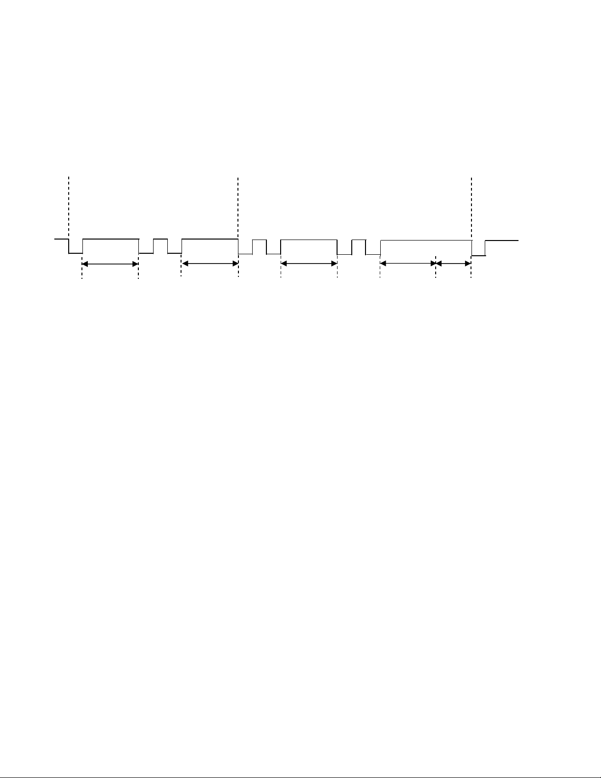
APPENDIX A. CHARACTER TIMING
The character timing is as follows:
Regular Character Special Character Next Character
Make Break Make Break Make
Scan Code Scan Codes Scan Codes Scan Codes Scan Code
Where D = Character delay specified by 01A parameter
Where T = Special character delay specified by 01B parameter (follows special character break code)
1/2 D 1/2 D T
Figure A-1. Character Timing Diagram
1/2 D
1/2 D
23
Page 30

MiniWedge Swipe Reader
24
Page 31

INDEX
A
AAMVA.......................................................................1, 17
ANSI ................................................................................. 1
AT-style Configuration – Old Style.................................. 7
B
BIOS................................................................................ 11
C
CA DL..........................................................................1, 17
CA ID...........................................................................1, 17
Cabling.............................................................................. 6
Card Data Format............................................................ 20
Card Reading..................................................................... 9
Character Delay............................................................... 14
Character Timing............................................................. 23
Class B device.................................................................. iv
Class B limits ................................................................... iv
Command Codes from the PC to the Reader................... 11
Command Sequences, Examples of................................ 20
Copyright......................................................................... 14
D
Data Error Conditions ..................................................... 21
Data Error Detected........................................................... 9
Device identifier.............................................................. 13
Device-specific Operation............................................... 12
Direct character modes.................................................... 14
Disable Keyboard............................................................ 14
Disable Reader ................................................................ 14
Driver License................................................................. 17
E
Enable Keyboard............................................................. 14
Enable PINPad................................................................ 13
Enable Reader ................................................................. 14
End Sentinel.................................................................... 17
Error.................................................................................. 9
Error Conditions.............................................................. 21
ETX................................................................................. 12
F
Features............................................................................. 1
Five-pin DIN Connector.................................................... 8
G
Get Track Configuration ................................................. 14
H
Hardware Installation.........................................................5
Hardware Track Mapping, P02A.....................................18
I
Installation.........................................................................5
ISO.....................................................................................1
ISO/ABA.........................................................................17
K
KB Flag, P080 .................................................................19
Keyboard ......................................................................... 18
L
LED
for status........................................................................1
green, ready to read and receive cmds........................11
orientation.....................................................................5
red detects start sentinel but no decode of magstripe.. 21
red for the invalid track............................................... 21
red if cannot decode magstripe data..............................9
red or flash red and green - internal problem................9
red until power removed.............................................11
slowly flash red and green if CRC wrong...................11
Lower Case......................................................................18
LRC ................................................................................. 17
M
MagWedge.......................................................................12
MagWedge Compatibility................................................15
MagWedge compatibility mode.......................................15
Message...........................................................................13
Message Format...............................................................11
Message prefix.................................................................13
MiniWedge Commands and Responses...........................13
Mounting ...........................................................................5
Mounting Hole Dimensions...............................................6
MTD ................................................................................11
N
Numeric Keypad..............................................................18
O
Operation.........................................................................11
P
Parameter Address List.................................................... 16
25
Page 32

MiniWedge Swipe Reader
Parameter Modifications................................................. 20
Parameter Table ID, P001............................................... 17
Parameter View............................................................... 14
Parameter Write............................................................... 14
PS/2-style Configuration – New........................................ 8
PS/2-style Configuration – Old Style................................ 7
R
Related Documents ........................................................... 2
Response Codes and Timing........................................... 13
Return ID......................................................................... 14
Status ........................................................................... 9, 14
STX..................................................................................12
T
Terminating Char, P022...................................................18
Terminator.......................................................................13
Track Data .......................................................................14
Track Data Send Flags, P014...........................................17
Track Error ......................................................................18
Track Mapping.................................................................18
Track/ID Enable, P013 ....................................................17
S
Scan codes....................................................................... 14
Scan set............................................................................ 11
Set Character Delay......................................................... 14
Set Track Configuration.................................................. 14
Shift Flag......................................................................... 19
Six-pin Mini DIN connector.............................................. 8
Specifications.................................................................... 2
Start Sentinel................................................................... 17
U
Upper Case ...................................................................... 18
US keyboard....................................................................19
US Keyboard Scan Code.................................................12
W
Windows Driver...............................................................11
26
 Loading...