

Page 1

MINI MICR USB
WITH OPTIONAL 3-TRACK MSR
TECHNICAL REFERENCE MANUAL
Manual Part Number: 99875252-4
JUNE 2003
REGISTERED TO ISO 9001:2000
1710 Apollo Court
Seal Beach, CA 90740
Phone: (562) 546-6400
FAX: (562) 546-6301
Technical Support: (651) 415-6800
www.magtek.com
Page 2
Copyright© 2002-2005
MagTek® Inc.
Printed in the United States of America
Information in this document is subject to change without notice. No part of this document may be
reproduced or transmitted in any form or by any means, electronic or mechanical, for any purpose,
without the express written permission of MagTek, Inc.
MagTek is a registered trademark of MagTek, Inc.
REVISIONS
Rev Date Notes
1 13 Dec 02 Initial Release
2 21 Feb 03 Sec 4: SWB Parameters, Communication
modes: deleted last sentence for clarification.
Added LE command and control table.
3 11 Mar 03 Replaced some fonts so manual would print on
all printers.
4 13 Jun 03 Front Matter: added ISO line to logo, changed
Tech Support phone number, and changed to
new warranty.
ii
Page 3

LIMITED WARRANTY
MagTek warrants that the products sold to Reseller pursuant to this Agreement will perform in accordance with
MagTek’s published specifications. This warranty shall be provided only for a period of one year from the date
of the shipment of the product from MagTek (the “Warranty Period”). This warranty shall apply only to the
original purchaser unless the buyer is authorized by MagTek to resell the products, in which event, this warranty
shall apply only to the first repurchase.
During the Warranty Period, should this product fail to conform to MagTek’s specifications, MagTek will, at its
option, repair or replace this product at no additional charge except as set forth below. Repair parts and
replacement products will be furnished on an exchange basis and will be either reconditioned or new. All replaced
parts and products become the property of MagTek. This limited warranty does not include service to repair
damage to the product resulting from accident, disaster, unreasonable use, misuse, abuse, customer’s negligence,
Reseller’s negligence, or non-MagTek modification of the product. MagTek reserves the right to examine the
alleged defective goods to determine whether the warranty is applicable.
Without limiting the generality of the foregoing, MagTek specifically disclaims any liability or warranty for
goods resold in other than MagTek’s original packages, and for goods modified, altered, or treated by customers.
Service may be obtained by delivering the product during the warranty period to MagTek (1710 Apollo Court,
Seal Beach, CA 90740). If this product is delivered by mail or by an equivalent shipping carrier, the customer
agrees to insure the product or assume the risk of loss or damage in transit, to prepay shipping charges to the
warranty service location and to use the original shipping container or equivalent. MagTek will return the product,
prepaid, via a three (3) day shipping service. A Return Material Authorization (RMA) number must accompany
all returns.
MAGTEK MAKES NO OTHER WARRANTY, EXPRESS OR IMPLIED, AND MAGTEK DISCLAIMS ANY
WARRANTY OF ANY OTHER KIND, INCLUDING ANY WARRANTY OF MERCHANTABILITY OR
FITNESS FOR A PARTICULAR PURPOSE.
EACH PURCHASER UNDERSTANDS THAT THE MAGTEK PRODUCT IS OFFERED AS IS. IF THIS
PRODUCT DOES NOT CONFORM TO MAGTEK’S SPECIFICATIONS, THE SOLE REMEDY SHALL BE
REPAIR OR REPLACEMENT AS PROVIDED ABOVE. MAGTEK’S LIABILITY, IF ANY, TO RESELLER
OR TO RESELLER’S CUSTOMERS, SHALL IN NO EVENT EXCEED THE TOTAL AMOUNT PAID TO
MAGTEK BY RESELLER UNDER THIS AGREEMENT. IN NO EVENT WILL MAGTEK BE LIABLE TO
THE RESELLER OR THE RESELLER’S CUSTOMER FOR ANY DAMAGES, INCLUDING ANY LOST
PROFITS, LOST SAVINGS OR OTHER INCIDENTAL OR CONSEQUENTIAL DAMAGES ARISING OUT
OF THE USE OF OR INABILITY TO USE SUCH PRODUCT, EVEN IF MAGTEK HAS BEEN ADVISED OF
THE POSSIBILITY OF SUCH DAMAGES, OR FOR ANY CLAIM BY ANY OTHER PARTY.
LIMITATION ON LIABILITY
EXCEPT AS PROVIDED IN THE SECTIONS RELATING TO MAGTEK’S LIMITED WARRANTY,
MAGTEK’S LIABILITY UNDER THIS AGREEMENT IS LIMITED TO THE CONTRACT PRICE OF THE
PRODUCTS.
MAGTEK MAKES NO OTHER WARRANTIES WITH RESPECT TO THE PRODUCTS, EXPRESSED OR
IMPLIED, EXCEPT AS MAY BE STATED IN THIS AGREEMENT, AND MAGTEK DISCLAIMS ANY
IMPLIED WARRANTY, INCLUDING WITHOUT LIMITATION ANY IMPLIED WARRANTY OF
MERCHANTABILITY OR FITNESS FOR A PARTICULAR PURPOSE.
MAGTEK SHALL NOT BE LIABLE FOR CONTINGENT, INCIDENTAL, OR CONSEQUENTIAL
DAMAGES TO PERSONS OR PROPERTY. MAGTEK FURTHER LIMITS ITS LIABILITY OF ANY KIND
WITH RESPECT TO THE PRODUCTS, INCLUDING ANY NEGLIGENCE ON ITS PART, TO THE
CONTRACT PRICE FOR THE GOODS.
MAGTEK’S SOLE LIABILITY AND BUYER’S EXCLUSIVE REMEDIES ARE STATED IN THIS SECTION
AND IN THE SECTION RELATING TO MAGTEK’S LIMITED WARRANTY.
iii
Page 4

FCC WARNING STATEMENT
This equipment has been tested and found to comply with the limits for Class B digital device, pursuant to Part 15
of FCC Rules. These limits are designed to provide reasonable protection against harmful interference when the
equipment is operated in a residential environment. This equipment generates, uses, and can radiate radio
frequency energy and, if not installed and used in accordance with the instruction manual, may cause harmful
interference to radio communications. However, there is no guarantee that interference will not occur in a
particular installation.
FCC COMPLIANCE STATEMENT
This device complies with Part 15 of the FCC Rules. Operation of this device is subject to the following two
conditions: (1) This device may not cause harmful interference; and (2) this device must accept any interference
received, including interference that may cause undesired operation.
CANADIAN DOC STATEMENT
This digital apparatus does not exceed the Class B limits for radio noise for digital apparatus set out in the Radio
Interference Regulations of the Canadian Department of Communications.
Le présent appareil numérique n’émet pas de bruits radioélectriques dépassant les limites applicables aux
appareils numériques de las classe B prescrites dans le Réglement sur le brouillage radioélectrique édicté par les
ministère des Communications du Canada.
CE STANDARDS
Testing for compliance to CE and FCC requirements was performed by an independent laboratory. The unit
under test was found compliant to Class B.
UL/CSA
This product is recognized per Underwriter Laboratories and Canadian Underwriter Laboratories 1950.
iv
Page 5

TABLE OF CONTENTS
SECTION 1. OVERVIEW.............................................................................................................................1
FEATURES...............................................................................................................................................1
ACCESSORIES........................................................................................................................................1
SOFTWARE DRIVERS REQUIRED ........................................................................................................2
SPECIFICATIONS....................................................................................................................................2
SECTION 2. INSTALLATION......................................................................................................................3
REQUIREMENTS.....................................................................................................................................3
PROCEDURE...........................................................................................................................................3
USB DRIVER INSTALLATION .................................................................................................................4
SECTION 3. OPERATION...........................................................................................................................5
CHECK READING PROCEDURE............................................................................................................5
CARD SWIPE PROCEDURE...................................................................................................................5
LED INDICATORS....................................................................................................................................6
SECTION 4. COMMANDS...........................................................................................................................7
INSTA-CHANGE CHECKS.......................................................................................................................7
MICRBASE SETUP PROGRAM FOR WINDOWS ..................................................................................7
MAGTEK DEVICE DRIVERS FOR WINDOWS .......................................................................................7
COMMAND FORMAT...............................................................................................................................8
SWA - SWITCH A COMMAND.................................................................................................................8
SWA PARAMETERS................................................................................................................................8
SWB - SWITCH B COMMAND.................................................................................................................9
SWB PARAMETERS..............................................................................................................................10
Control Characters and MICR Data ...................................................................................................10
Control Characters and Card Data.....................................................................................................10
Communication Modes.......................................................................................................................10
Send Data After Error.........................................................................................................................11
Send Status After Data.......................................................................................................................11
SWC - SWITCH C COMMAND ..............................................................................................................12
SWC PARAMETERS..............................................................................................................................13
CMC-7 Character Set.........................................................................................................................13
Invalid Command Response ..............................................................................................................13
Data Header .......................................................................................................................................14
Card Data Message............................................................................................................................14
HW - HARDWARE COMMAND..............................................................................................................15
HW PARAMETERS................................................................................................................................16
Disable/Enable Tracks........................................................................................................................16
ID Card Decoding...............................................................................................................................16
EMF Detect.........................................................................................................................................16
FC - FORMAT CHANGE COMMAND....................................................................................................16
VR - VERSION COMMAND....................................................................................................................17
LE - LED COMMAND .............................................................................................................................17
SA - SAVE COMMAND ..........................................................................................................................18
RS - RESET COMMAND........................................................................................................................18
APPENDIX A. FORMAT LIST...................................................................................................................19
APPENDIX B. CHECK READING..............................................................................................................37
v
Page 6

E13-B CHARACTER SET...................................................................................................................... 37
CMC-7 CHARACTER SET..................................................................................................................... 37
CHECK LAYOUTS.................................................................................................................................38
MICR FIELDS.........................................................................................................................................39
1-Transit Field ....................................................................................................................................39
2-On-Us Field.....................................................................................................................................39
3-Amount Field...................................................................................................................................40
4-Auxiliary On-Us Field...................................................................................................................... 40
APPENDIX C. TROUBLESHOOTING GUIDE.......................................................................................... 41
REQUIREMENTS................................................................................................................................... 41
SET-UP................................................................................................................................................... 41
00 CHECK LED.............................................................................................................................. 41
01 CHECK THE POWER TO THE MICR READER ...................................................................... 42
02 READ A CHECK........................................................................................................................ 42
03 DID PC RECEIVE DATA?.........................................................................................................42
04 ANALYZE DATA........................................................................................................................ 42
05 VERIFY PARAMETERS............................................................................................................43
06 READ ERROR........................................................................................................................... 43
07 MISSING CHARACTERS.......................................................................................................... 44
08 COMMUNICATION PARAMETERS DO NOT MATCH ............................................................ 44
09 INCORRECT FORMAT.............................................................................................................44
10 PATH IS OBSTRUCTED...........................................................................................................45
11 MOTOR SENSOR IS BLOCKED.............................................................................................. 45
12 EMF NOISE/INTERFERENCE.................................................................................................. 45
13 DATA SENSOR IS BLOCKED.................................................................................................. 46
14 NO MICR DATA DETECTED....................................................................................................46
15 CABLE PROBLEM....................................................................................................................46
16 NO PROBLEM FOUND............................................................................................................. 47
17 READ INSTA-CHANGE CHECK............................................................................................... 47
18 RETURN MICR READER TO MAGTEK...................................................................................47
APPENDIX D. ASCII CODES ................................................................................................................... 49
FIGURES
Figure 1-1. MINI MICR USB with 3-Track MSR ........................................................................................viii
Figure 3-1. Check Orientation...................................................................................................................... 5
Figure B-1. Personal Checks....................................................................................................................38
Figure B-2. Business Checks ....................................................................................................................39
Figure C-1. Sensor Location......................................................................................................................47
vi
Page 7

TABLES
Table 1-1. Specifications..............................................................................................................................2
Table 3-1. LED indicators.............................................................................................................................6
Table 4-1. SWA Command ..........................................................................................................................8
Table 4-2. SWB Command ..........................................................................................................................9
Table 4-3. Control Characters....................................................................................................................10
Table 4-4. Error and Status Codes ............................................................................................................11
Table 4-5. SWC Command........................................................................................................................12
Table 4-6. HW Command ..........................................................................................................................15
Table 4-7. LED Control...............................................................................................................................17
Table B-1. CMC-7 Nonnumeric Characters................................................................................................38
vii
Page 8
viii
Figure 1-1. MINI MICR USB with 3-Track MSR
Page 9

SECTION 1. OVERVIEW
The MINI MICR USB With Optional 3-Track MSR is both a MICR (Magnetic Ink Character
Recognition) Check Reader and an MSR (Magnetic Stripe Reader).
The MICR Reader, in a typical application, reads the magnetic data encoded on the bottom of
checks or magnetic stripe cards and transmits this data to a Host device. The Host device then
uses a specific authorization or verification process to validate a business transaction.
The use of the MICR Reader improves accuracy and speed because there is no manual data
entry; therefore there are no keying errors or unwanted delays.
The MICR Reader will communicate with the Host system using a standard USB interface. The
driver will emulate a serial port on the host PC. All data is transmitted as ASCII characters (See
Appendix D).
FEATURES
• Available with MICR Reader only or with 3-Track or 2-Track MSR.
• Three track MSR autodiscriminates different card formats: ISO (International Standards
Organization), CDL (California Drivers License), or AAMVA (American Association of
Motor Vehicle Administrators).
• Small footprint.
• Automatic parsing of MICR fields: transit, account, etc.
• Extensive list of formats to transmit MICR data.
• Optional error/status reporting for check reading.
• Reads E13-B and CMC-7 MICR fonts.
• EMF noise detection
• In addition to the USB interface, the MICR Reader is also available with other interfaces.
ACCESSORIES
Accessories available for the MICR Reader are as follows:
• MagTek Device Drivers for Windows, Part Number 30037385
• MagTek Device Drivers for Windows, Programming Reference Manual, Part Number
99875125
• Interface Cable, 9-pin Mini Din, Male, USB A Plug, 6’, Beige, Part Number 22517582, or
• Interface Cable, 9-pin Mini Din, Male, USB A Plug, 6’, MT Gray, Part Number 22517583
• AC Power Adapter with Cable, 120VAC to 12 VAC, 1 Amp, Part Number 64300050
• MICRbase Program, Part Number 22000021
• MICRbase, Setup Program for MICR Readers, Programming Reference Manual, P/N
99875102
1
Page 10

MINI MICR USB with 3-Track MSR
• MICR Reader Cleaning Card, Part Number 96700006
• Sample Checks, Part Number 96530005
SOFTWARE DRIVERS REQUIRED
The USB driver files are available in two forms:
- On a CD (P/N 30035077)
- From the MagTek web site (www.magtek.com) (P/N 99510038).
Refer to the USB Driver Installation in Section 2 for information on installing the drivers.
SPECIFICATIONS
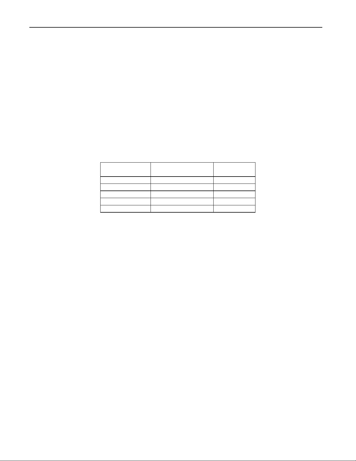
Table 1-1 lists the specifications for the MICR Reader.
Reference Standards ISO/CDL/AAMVA
Power Input 120 VAC, 50/60 Hz
Output Signal Levels 12 VAC, 1 Amp
Check Read/Decode/Transit
Time
MICR fonts supported E13-B
MSR supported Tracks 1, 2, and 3; or Tracks 1 and 2
Dimensions Length 6.0”, Width 4.0”, Height 4.25”
Weight: 3.0 lbs. MSR and Adapter included
Cable length 6’
Connectors DIN-9, USB A
1 second
CMC-7
Temperature
Operating 0oC to 50oC (32oF to 122oF)
Storage -30oC to 70oC (-22oF to 158oF)
Humidity
Operating 10% to 90% noncondensing
Storage Up to 100% noncondensing
Table 1-1. Specifications
OPERATING
MECHANICAL
ENVIRONMENTAL
2
Page 11

SECTION 2. INSTALLATION
The installation for the MICR Reader is as follows:
REQUIREMENTS
The following is required for the Installation:
• MINI MICR USB With Optional MSR
• Interface Cable, 9-pin Mini Din, Male, USB A Plug, 6’, Beige, Part Number 22517582, or
• Interface Cable, 9-pin Mini Din, Male, USB A Plug, 6’, MT Gray, Part Number 22517583
• AC Power Adapter with Cable, 120VAC to 12 VAC, 1 Amp, Part Number 64300050
• Master USB Driver P/N On a CD (Part Number 30035077) or from the MagTek web site
(www.magtek.com) (Part Number 99510038).
PROCEDURE
Perform the following steps:
1. On the interface cable connect the USB A connector to the PC.
2. On the interface cable connect the 9-pin male DIN connector to the MICR Reader.
3. On the AC power adapter, connect the jack to the plug on the MICR Reader.
4. On the AC power adapter, connect the plug to the wall outlet.
5. The first time the Reader is connected to the PC, Windows will need to install the USB
driver. See the instructions below.
6. The LED indicator on the MICR Reader should turn on to a steady green. The LED
indicator is located below the slot where the check is first inserted for reading.
Caution
Do not place the MICR Reader within 6 inches of a computer
monitor or power supply. These devices may cause undesirable
interference with the check reading operation.
3
Page 12

MINI MICR USB with 3-Track MSR
USB DRIVER INSTALLATION
When using the USB version of the Mini MICR, you must install the appropriate files on your
computer. The USB devices will only operate on computers with Windows 98/ME/2000/XP
operating systems.
The USB driver files are available in two forms:
- On a CD (p/n 30035077)
- From the MagTek web site (www.magtek.com) (p/n 99510038). (The files on the
web site are provided in a self-extracting zip file. Run the application and unzip the
files to a temporary folder on your local disk drive.)
If you have the CD or after you have extracted all the files, proceed with installation steps below.
These steps will only have to be performed the first time you attach the device.
1) After the USB cable and the power adapter have been connected to the device and to the
PC, Windows will indicate that it found new hardware and will show the Mini MICR
device has been attached.
2) You will then be prompted to use the USB Wizard to install the device driver and other
appropriate files.
3) When prompted, ask the Wizard to search for a suitable device driver.
4) If you have the MagTek USB drivers on a CD, specify the CD drive as the location of the
driver. If you used the web installation, you many use the Browse button to specify the
location to where the files were extracted.
5) After you locate the requested INF file, click Open.
6) After all of the files have been installed, click Finish.
After the files have been installed, any application program can communicate with the Mini
MICR just as if it is attached to a regular RS-232 COM port. If your application can
automatically detect the available COM ports, the newly installed USB device will be shown as
one of the available COM ports (e.g., COM5).
If your application does not support COM port selection, you can determine the COM port
number by using the device manager. This can be done by right-clicking on the My Computer
icon on the desktop; then select Properties. In Windows 98/ME, click the Device Manager tab;
in Windows 2000/XP, click the Hardware tab, then Device Properties. When the Device
Manager window opens, click on the plus sign next to Ports (COM & LPT). The new device
will be shown in the list with its COM port identified.
4
Page 13
SECTION 3. OPERATION
This section contains check and card reading procedures and LED indicator states.
CHECK READING PROCEDURE
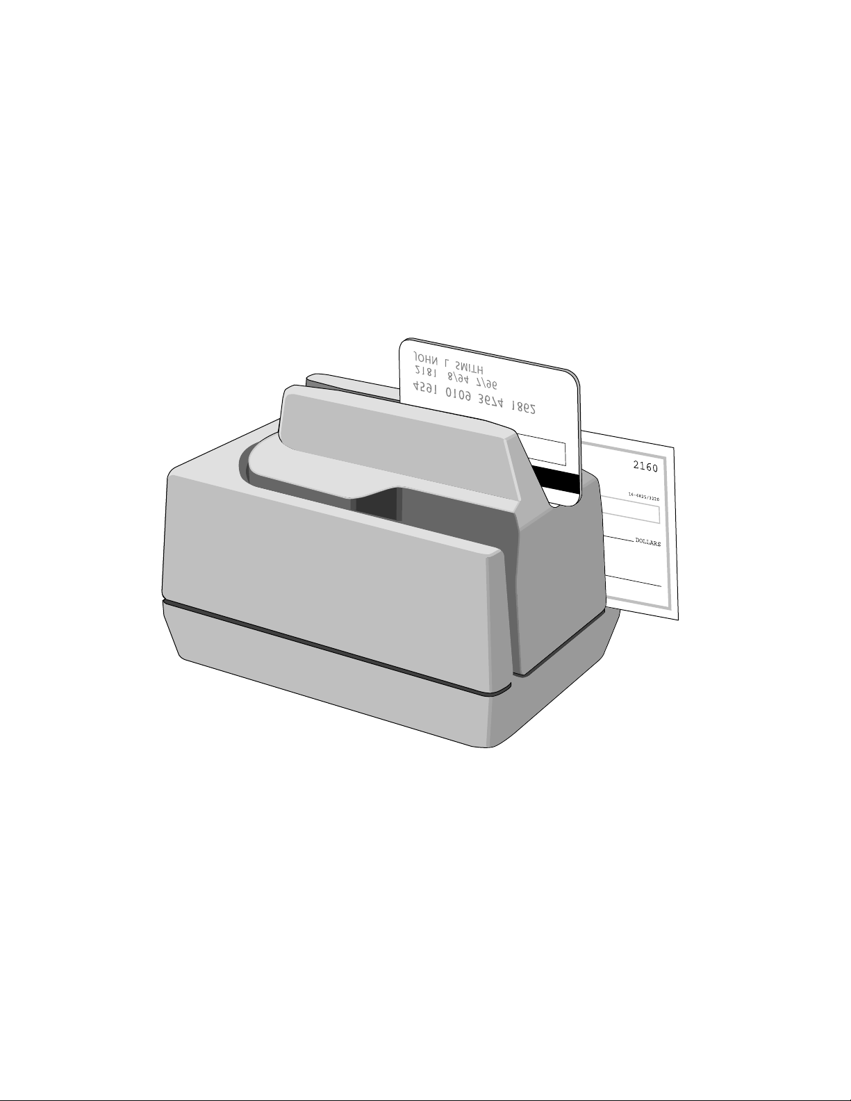
1. Orient the check so the MICR line is down and the printed side faces the center on the MICR
Reader as shown in Figure 3-1.
Figure 3-1. Check Orientation
2. Drop the check so the leading edge is in the open slot.
3. When the MICR Reader detects the presence of the check, the motor will turn on. At this time
gently urge the check forward until the unit grabs the check. When this happens, release the
check. The check will then be transported around the check path and will exit through the other
side.
4. After the check is read, the MICR Reader will transmit the data as specified by the parameters
described in Section 4, Commands.
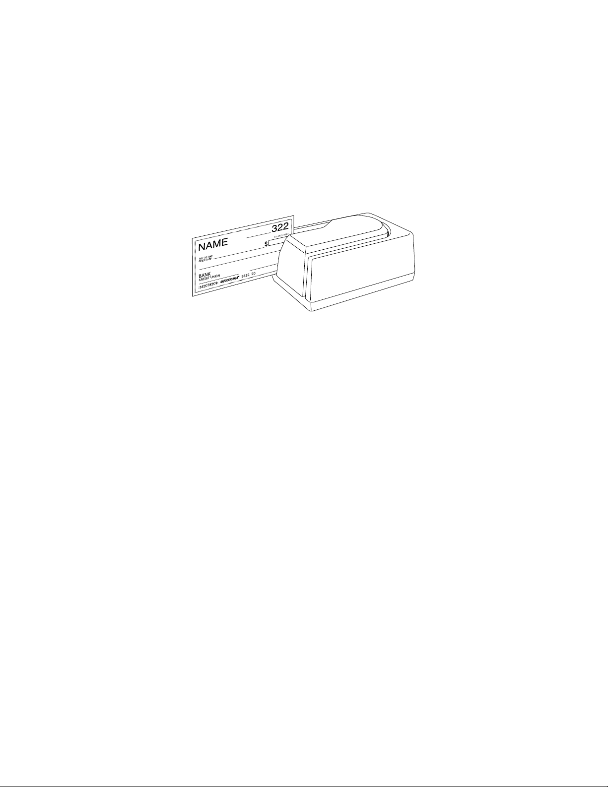
CARD SWIPE PROCEDURE
The card may be swiped through the MSR in either direction, but the magnetic stripe must be oriented in
only one direction as shown in Figure 1-1. The MSR will transmit raw card data (“as is” on the card) for
all tracks that have been enabled using the HW (Hardware) command (Section 4, Commands).
The MSR is capable of reading ISO, AAMVA, and CDL encoded cards. The MSR will autodiscriminate
all the card formats when the ID Card Decoding option is enabled using the HW (Hardware) command
(Section 4, Commands).
5
Page 14

MINI MICR USB with 3-Track MSR
LED INDICATORS
Table 3-1 describes the LED indicator conditions for check and card reading operations. The LED
indicator is located below the slot where the check is first inserted for reading.
Table 3-1. LED indicators
LED INDICATOR DESCRIPTION
OFF Power off
SOLID GREEN Ready to read check or card
OFF→ SOLID RED
OFF→ SOLID GREEN
FLASH GREEN Needs initialization*
FLASH RED/GREEN Data sensor blocked (motor does not run)*
FLASH RED Motor sensor blocked (motor does not run)*
FLASH GREEN FAST Monitor mode (factory use only)*
*Refer to “Appendix C. Troubleshooting Guide.”
Check or card read error
Good read
6
Page 15

SECTION 4. COMMANDS
This section describes the use of commands and programmable options available for the MICR Reader.
Note
All options described below can be factory set as specified by the user when
ordering.
To execute the MICR Reader commands, either one of two methods is required: Insta-Change checks or
the MICRbase Setup Program for Windows.
INSTA-CHANGE CHECKS
The first method is the use of Insta-Change checks, which is a more practical way of setting up the
MICR Reader for most applications. The Insta-Change check is a MICR encoded document that
contains commands and options used to reset the parameters of the MICR Reader. Multiple
commands and options may be contained on one Insta-Change check. When used, the InstaChange checks are run through the MICR Reader the same as a standard check, and the options to
be used are automatically selected. To obtain Insta-Change checks, notify a MagTek
representative and specify what options will be used. To operate Insta-Change checks, install the
MICR Reader as described in Section 2, and watch the LED indicator. When the Insta-Change
check is run through the MICR Reader and read successfully, the LED indicator will blink green.
If the LED indicator turns red, the read is not successful. Try again or use a different InstaChange check.
MICRBASE SETUP PROGRAM FOR WINDOWS
The MICRbase setup program (P/N 22000021) allows the user to control all the programmable
options available in the MICR Reader.
The program provides a graphical, user-friendly interface that hides the complexities involved in
manually entering MICR commands. The user is no longer required to know the specific commands
or the detailed data associated with each command. However, the program still allows manual entry
of commands for advanced users. For more detailed information refer to the MICRbase Setup
Program Reference Manual (P/N 99875102).
The MICRbase setup program may also be downloaded from the internet at www.magtek.com under
Software/Demo Programs.
MAGTEK DEVICE DRIVERS FOR WINDOWS
For Windows applications, the MagTek Device Drivers for Windows (P/N 30037385) are available
to simplify the programming of the MICR Reader. The drivers are easy to install, and they facilitate
the execution of MICR Reader commands. For more detailed information, refer to the MagTek
Device Driver for Windows, Programming Reference Manual (P/N 99875125).
The drivers may also be downloaded from the Internet at www.magtek.com Software/Device
Drivers.
7
Page 16
MINI MICR USB with 3-Track MSR
COMMAND FORMAT
When the commands are entered manually, they must use the following format:
[COMMAND][DATA]<CR>
where:
• [COMMAND] is 2 or 3 alpha characters.
• [Data] is optional as described below for each command.
• <CR> is always required.
• All characters are ASCII
• No spaces, brackets, or angle brackets required.
SWA - SWITCH A COMMAND
The SWA command controls the communication parameters, shown in Table 4-1. The data for
this command consists of 8 ASCII bits (“0” = hex 30 and “1” = hex 31).
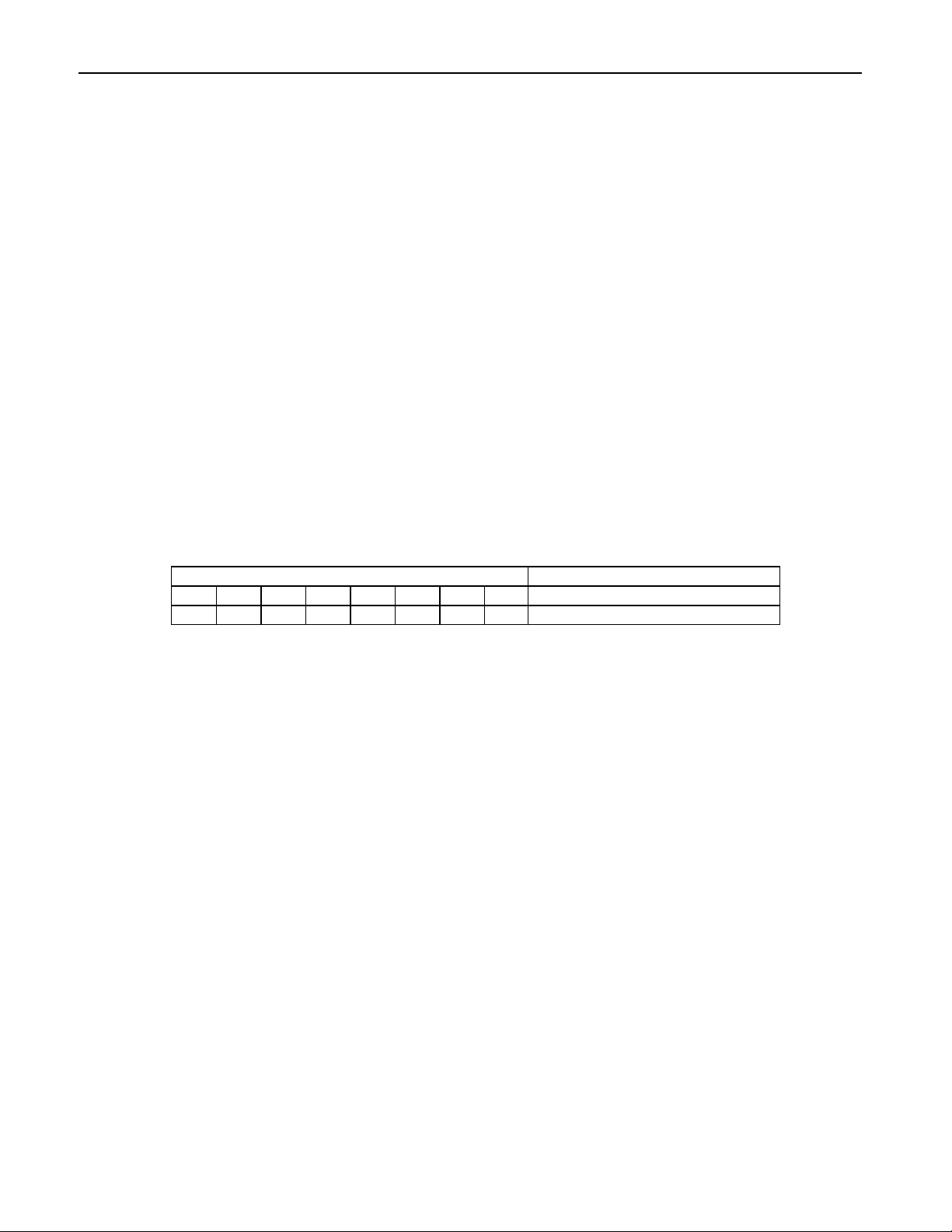
Table 4-1. SWA Command
BITS PARAMETERS
7 6 5 4 3 2 1 0
x x x x x x x x Not Used
To execute, send the SWA command as follows:
SWA 01010101<CR> (with data)
or
SWA <CR> (without data)
When sending data, all 8 bits must be provided. The MICR Reader will execute the command but
it will not reply. To make this command permanent, use the SA (Save) command described at the
end of this section.
If no data is sent, the MICR Reader responds with the current settings for SWA.
SWA PARAMETERS
SWA Has no affect on the Reader and is included only to maintain compatibility with our other
MICR Readers.
8
Page 17

Section 4. Commands
SWB - SWITCH B COMMAND
The SWB command controls the message format, shown in Table 4-2. The data for this command
consists of 8 ASCII bits (“0” = hex 30 and “1” = hex 31).
To execute, send the SWB command as follows:
SWB 01010101<CR> (with data)
or
SWB <CR> (without data)
When sending data, all 8 bits must be provided. The MICR Reader will execute the command but
it will not reply. The new settings become effective immediately. To make this command
permanent, use the command SA (Save) described at the end of this section.
If no data is sent, the MICR Reader responds with the current settings for SWB.
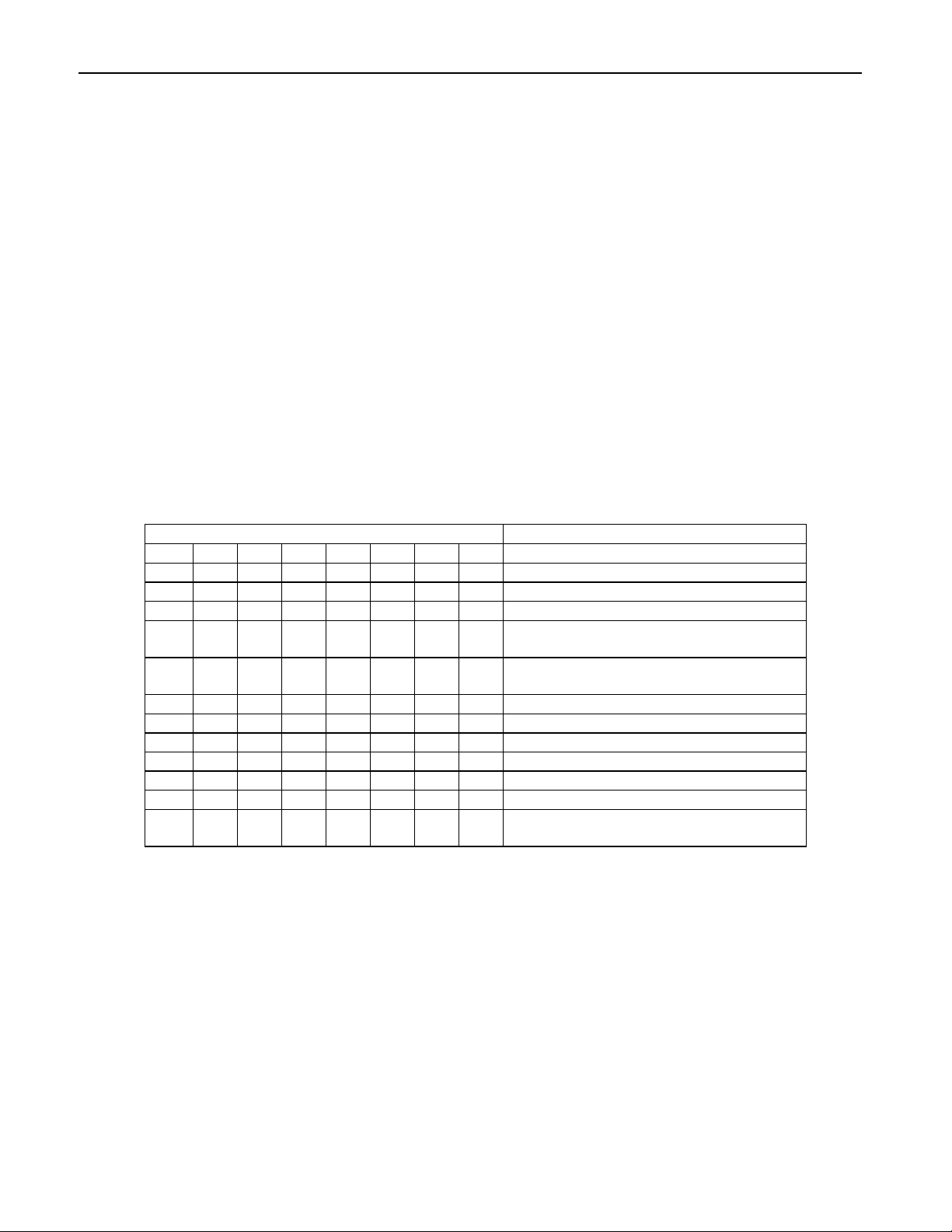
Table 4-2. SWB Command
BIT PARAMETERS
7 6 5 4 3 2 1 0
0 <LF>: No
1 <LF>: Yes
0 <CR>: No
1 <CR>: Yes
0 <ETX>: No
1 <ETX>: Yes
0 <ESC>: No
1 <ESC>: Yes
0 <STX>: No
1 <STX>: Yes
0 Send Data After Error?: No
1 Send Data After Error?: Yes
0 Send Status After Data?: No
1 Send Status After Data?: Yes
0 0 0 0 0 0 Comm Mode: 0 - Data Only
1 0 0 0 0 0 Comm Mode: 1 - Data <CR>
0 0 0 0 0 1 Comm Mode: 2 - Data -<LF>
0 0 0 0 1 1 Comm Mode: 3 - Data -<CR><LF>
0 0 1 0 0 0 Comm Mode: 4 - <ESC> Data
0 0 1 0 1 0 Comm Mode: 5 - <ESC> Data<CR>
0 1 0 1 0 0 Comm Mode: 6 - <STX> Data<ETX>
1 0 0 0 0 1 Comm Mode: 7 - <STX>Data<ETX><LRC>
9
Page 18
MINI MICR USB with 3-Track MSR
SWB PARAMETERS
The SWB functions are listed in Table 4-2 and described below.
Control Characters and MICR Data
Control Characters may be added to the MICR data message. The characters are always in the
following locations:
<STX> <ESC> data <ETX> <CR> <LF>
The control characters, descriptions, and hex values are shown in Table 4-3.
Table 4-3. Control Characters
CONTROL
CHARACTER
<STX> Start of Text 02
<ESC> Escape 1B
<ETX> End of Text 03
<CR> Carriage Return 0D
<LF> Line Feed 0A
DESCRIPTION
HEX VALUE
For example, if <STX> and <CR> are set to YES, the message from the MICR Reader will look
like this:
MICR Data: <STX>data<CR>
Control Characters and Card Data
The control characters are also available for card data but they are applied to each track
individually. For example, if the <STX> and <ETX> options are set to YES, the card data
message is transmitted as follows:
Card Data: <STX>[TK1 data]<ETX><STX>[TK2 data]<ETX><STX>[TK3 data]<ETX>
Communication Modes
The selection of comm modes is a quick way of selecting multiple Control Characters. For
instance, to send a carriage return/line feed pair after the data, you can specify Comm Mode 3.
Comm Mode 7, also known as Packet Mode, calculates an LRC (Longitudinal Redundancy
Check), and appends it to the data message. Also, if a <NAK> (hex 15) character is received in
this mode, the MICR Reader will resend the last message.
10
Page 19

Section 4. Commands
Send Data After Error
The request Send Data After Error specifies whether the MICR Reader will return data to the Host
after a read error. If YES is selected and the MICR Reader detects a read error, the MICR Reader
will still send the data back to the Host. If NO is selected and the MICR Reader finds an error, it
will discard the data and nothing will be sent. The error conditions are listed in Table 4-4.
Send Status After Data
The Send Status After Data option makes the MICR Reader append a two-digit error/status code
to the end of the MICR data. For most formats (See Appendix A), the error/status code will
always be preceded by a forward slash (/). The error/status codes are listed in Table 4-4.
For example, if a Canadian check (code 08) is read and had no errors, and the MICR data is
“1234567890”, then the message from the MICR Reader will look like this:
MICR Data: 1234567890/08
The status code is always at the end of the data, not the end of the message. For example, using
the above conditions, with the message format set to send <STX> and <ETX>, the message from
the MICR Reader will look like this:
MICR Data: <STX>1234567890/08<ETX>
Table 4-4. Error and Status Codes
PRIORITY CODE TYPE DESCRIPTION
9 01 Error No MICR data: no transit and no account found
8 09 Status Mexican check
7 08 Status Canadian check
6 05 Error Transit error: No transit, bad character, bad
length, bad check digit
5 07 Error Account error: No account, bad character
4 04 Error Check # error: Bad character in check number
4 04 Status No check number
3 03 Status Low MICR signal, good read
2 10 Status Business check
1 11 Status Amount field present
0 00 Status Good read
Notes:
• The LED indicator will turn red on all error conditions.
• The absence of a check number is not considered and error.
• If a multiple error condition occurs, the error or status code with the highest priority is reported.
• All unreadable MICR characters are transmitted as an “?” ASCII character (hex 3F), except for
Format 00xx (See Appendix A).
11
Page 20
MINI MICR USB with 3-Track MSR
SWC - SWITCH C COMMAND
The SWC command controls miscellaneous functions, shown in Table 4-5. The data for this
command consists of 8 ASCII bits (“0” = hex 30 and “1” = hex 31).
To execute, send the SWC command as follows:
SWC 01010101<CR> (with data)
or
SWC <CR> (without data)
When sending data, all 8 bits must be provided. The MICR Reader will execute the command but
it will not reply. The new settings become effective immediately. To make this command
permanent, use the SA (Save) command described at the end of this section.
If no data is sent, the MICR Reader responds with the current settings for SWC.
Table 4-5. SWC Command
BITS PARAMETERS
7 6 5 4 3 2 1 0
0 CMC-7 Character Set: No
1 CMC-7 Character Set: Yes
0 0 Invalid Commands: ?<CR>
0 1 Invalid Commands : No Reply (Header
Required)*
1 0 Invalid Commands: No Reply (No
Header Required)
1 1 Ignore all Commands
0 Reserved
0 Data Header: No
1 Data Header: Yes
0 Card Data Message: Multiple
1 Card Data Message: Single
0 0 These bits are always set to 0 but must
be included.
*Header Required means all commands must be preceded by a GS character (Hex 1D).
12
Page 21

Section 4. Commands
SWC PARAMETERS
The SWC functions are listed in Table 4-5 and described below.
CMC-7 Character Set
If NO is selected the MICR Reader will only read E13-B characters. When YES is selected, the
MICR Reader will read both CMC-7 and E13-B characters (see Appendix B). However, the
MICR Reader will only output raw data ("as is" on the check) for checks with CMC-7 characters.
Invalid Command Response
Invalid command response is the action the MICR Reader takes upon receipt of a command it
does not recognize. It can also be used to stop the MICR Reader from receiving any more
commands.
The first option “?<CR>” is the default. If the MICR Reader receives an unrecognized
command, it will return a question mark and carriage return to the Host. The MICR Reader will
then return to an idle state and wait for further commands or check/credit card reads.
For the second option, “no reply - header required,” the MICR Reader will only execute
commands preceded by a GS ASCII character (hex 1D). All other commands will be ignored.
Also, the MICR Reader will not reply to invalid commands.
For the third option, “no reply,” the MICR Reader will execute all valid commands, but it will not
reply to invalid commands.
The fourth option, “ignore all commands,” causes the MICR Reader to ignore any further
commands. Even the SA (Save) command is ignored and therefore this fourth option is only
temporary. To make this option permanent or to reset it, you must use an Insta-Change check.
13
Page 22

MINI MICR USB with 3-Track MSR
Data Header
If YES is selected, a single character header precedes the data. For MICR data, the message is
transmitted as follows:
MICR data: ‘C’[data]
For card data, the header position on the message is controlled by the Card Data Message
parameter (see below). Therefore, the message may be transmitted as follows:
If Multiple Message: ‘M’[TK1]‘M’[TK2]’M’[TK3]
If Single Message: ‘M’[TK1] [TK2] [TK3]
It is important to note that the Data Header precedes the data and not the message. For example, if
<STX>, <ETX> and Data Header are set to YES, a MICR data message will be transmitted as
follows:
MICR data: <STX>‘C’[data]<ETX>
Card Data Message
This option determines the structure of the output message for the individual tracks when a credit
card is read. If Multiple is selected, the Control Characters (see SWB, below) and Data Header
(see Data Header, above) are added to each track individually. On the other hand, if Single is
selected, all available tracks are lumped together into a single message. For example, if <STX>,
<ETX> and Data Header are set to YES, the output message may be transmitted as follows:
If Multiple Message: <STX>‘M’[TK1]<ETX><STX>‘M’[TK2]<ETX><STX>‘M’[TK3]<ETX>
If Single Message: <STX>‘M’[TK1] [TK2] [TK3]<ETX>
14
Page 23

Section 4. Commands
HW - HARDWARE COMMAND
This command controls miscellaneous hardware options, shown in Table 4-6. The data for this
command consists of 8 ASCII bits (“0” = hex 30 and “1” = hex 31).
To execute, send the HW command as follows:
HW 01010101<CR> (with data)
or
HW <CR> (without data)
When sending data, all 8 bits must be provided. The MICR Reader will execute the command but
it will not reply. The new settings become effective immediately. To make this command
permanent, use the SA (Save) command described at the end of this section.
If no data is sent, the MICR Reader responds with the current settings for HW.
Table 4-6. HW Command
7 6 5 4 3 2 1 0 PARAMETERS
0 Track 3: Disable
1 Track 3: Enable
0 Track 2: Disable
1 Track 2: Enable
0 Track 1: Disable
1 Track 1: Enable
0 ID Card decoding: Disable
1 ID Card decoding: Enable
0 EMF detect: Yes
1 EMF detect: No
0 0 0 These bits are always set to 0
15
Page 24

MINI MICR USB with 3-Track MSR
HW PARAMETERS
Disable/Enable Tracks
Each Track can be enabled or disabled individually. The tracks are always transmitted in
ascending order: TK1, TK2, TK3. For example, if TK1 and TK3 are enabled and TK2 is disabled,
the MSR will transmit TK1, TK3.
ID Card Decoding
The MSR has two modes of operation. In the first mode, ID Card decoding disabled, the MSR will
only read ISO encoded cards. In the second mode, ID Card decoding enabled, the MSR will read
and autodiscriminate ISO, AAMVA, and CDL encoded cards. When a card is swiped, the LED
indicator will turn red and indicate an error if any of the enabled tracks read is incompatible with
the selected mode of operation. TK2 is a standard track for all types of cards.
EMF Detect
The EMF Detect option allows the MICR Reader, when idle, to monitor EMF interference in its
immediate environment. If YES is selected, the LED indicator will blink red/green when the
MICR Reader detects a signal with amplitude large enough to affect check reading. If NO is
selected, the MICR Reader will not monitor nor indicate the presence of EMF interference.
FC - FORMAT CHANGE COMMAND
Formats are used by the MICR Reader to process and transmit the MICR fields. The format
command allows the selection of a format from the Format List, Appendix A. The data for this
command consists of 4 digits (ASCII characters 0-9). To execute, send the command as follows:
FC 6600<CR> (with data)
or
FC <CR> (without data)
When sending data, all 4 digits must be provided. The MICR Reader will execute the command
but it will not reply. The new settings become effective immediately. To make this command
permanent, use the SA (Save) command described below.
If no data is provided, the MICR Reader will respond with the current format number.
16
Page 25
Section 4. Commands
VR - VERSION COMMAND
The Version command gives the current software revision in the MICR Reader. To execute, send
the VR command followed by a carriage return as follows:
VR<CR>
The MICR Reader responds as follows:
MICR data: [software revision]<CR>
LE - LED COMMAND
To control the LED, the LE command is sent with a hexadecimal digit (use ASCII characters for
the hex digit):
LE X<Enter>
Where X = Hex digit 0-F.
An example of the “Blink Red” command is:
LE 9<Enter>
The codes and descriptions are shown in Table 4-7. The LE command will control the LED for three
seconds and then return it to the normal state. The description column is a common expression of the
state of the LED.
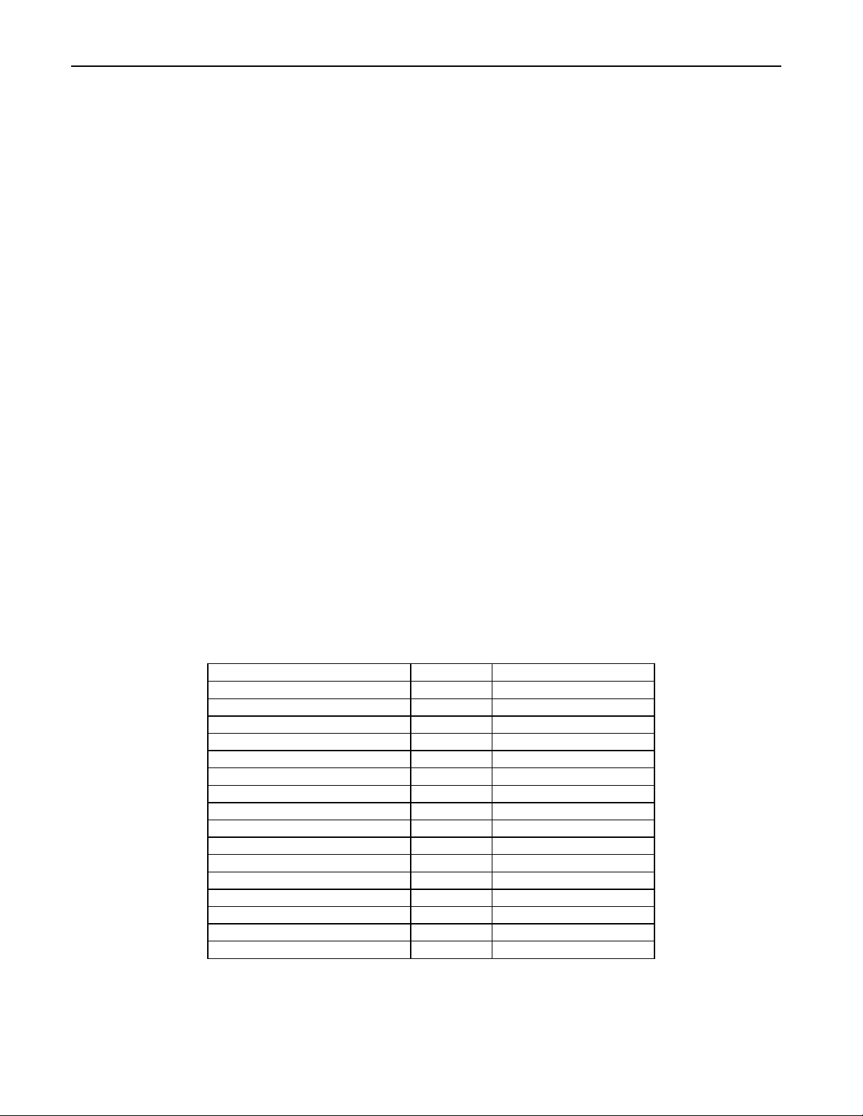
Table 4-7. LED Control
Color Cycle
Off/Off/Off/Off 0 LED Off
Green/Green/Green/Green 1 Steady Green
Red/Red/Red/Red/ 2 Steady Red
Amber/Amber/Amber/Amber 3 Steady Amber
Green/Green/Off/Off 4 Blink Green
Red/Red/Off/Off 5 Blink Red
Amber/Amber/Off/Off 6 Blink Amber
Red/Red/Green/Green 7 Blink Red/Green
Green/Off/Green/Off 8 Blink Green
Red/Off/Red/Off 9 Blink Red
Amber/Off/Amber/Off A Blink Amber
Red/Green/Red/Green B Blink Red/Green
Red/Green/Off/Off C Blink Red/Green
Green/Green/Green/Red D Blink Red/Green
Red/Red/Red/Green E Blink Red/Green
Off/Off/Off/Off F Off
Hex Digit Description
17
Page 26

MINI MICR USB with 3-Track MSR
SA - SAVE COMMAND
All changes are considered temporary until the Save command is executed. The Save command
saves all changes to the MICR Reader memory and makes them permanent. The MICR Reader
will execute the command but it will not reply. To execute, send the SA command followed by a
carriage return as follows:
SA<CR>
RS - RESET COMMAND
The Reset command resets the MICR firmware to the normal operating state of waiting for a
check or card to be read. The command also resets the serial port to the most recent settings
provided by the SWA command. To execute, send the RS command followed by a carriage return
as follows:
RS<CR>
18
Page 27

APPENDIX A. FORMAT LIST
For check reading, the MICR Reader provides the flexibility to format the MICR fields and build a
specific output string that will be transmitted to the Host. These output strings are referred to as formats.
The Reader has a built-in list of formats (described below) from which the user may select one to become
the active format every time a check is read. The formats may be selected using the FC command (Section
4, Commands) or Insta-Change checks provided by MagTek.
Each format is assigned a 4-digit number. The first two digits indicate the format number, and the last two
digits are specific parameters used for various functions by each format. For example, in format “0415”,
the “04” refers to format number 4 and the 15 refers the maximum number of characters allowed for the
account field.
Note
The formats listed in this section apply only to U.S. and Canadian checks.
The MICR line on checks from other countries will not be broken or parsed
as described in these formats.
A complete description for each format follows.
Fmt 00xx:
Xx - specify what symbol set to use. Choose from the table
Add xx + 16 - change multiple spaces to one space
Add xx + 32 - Remove all spaces
Examples:
MICR LINE: T122000218T 1234 5678 9U 1321
FC0001 - t122000218t 1234 5678 9o 1321
Raw Data Format - sends the entire MICR line - where:
(+16) FC0017 - t122000218t 1234 5678 9o 1321
(+32) FC0033 - t122000218t123456789o1321.
xx Transit On-Us Amount Dash Error
00 T U $ - ?
01 t o a d ?
02 T O A D ?
03 T U $ - *
04 T U $ 0 ?
05 T U $ 0 *
06 t o a 0 ?
07 T U $ none ?
19
Page 28

MINI MICR USB with 3-Track MSR
Fmt 01xx:
FC0100 - Parsed text with dashes
FC0101 - Parsed text, replace dashes with “d”
Field Labels - TR-transit, AC-account #, CK-check #, AM-amount, TP-tpc,
EP-epc
Example: - PTTR444455556;AC 999-222-3;CK11045
Fmt 02xx:
FC0200 - Parsed text with dashes
FC0201 - Parsed text, replace dashes with “d”
Error Labels - PE-parsed error, NE-no error, TR-transit error,
CK-chk # error, TC-transit check digit error,
AM-amount error, OU-on us/account# error, TP-tpc error
Examples: - PTTR444455556;AC999-222-3;CK11045/PENE
Fmt 03xx:
• [acct #]: - maximum of xx characters; when xx=00 all characters are sent
- keep spaces and dashes
Fmt 04xx:
• [acct #]: - maximum of xx characters; when xx=00 all characters are sent
- remove spaces and dashes
Fmt 05xx:
• [acct #]: - maximum of xx characters; when xx=00 all characters are sent
- replace spaces and dashes with zeros
Fmt 06xx:
• [acct #]: - always xx characters, zero filled;
when xx=00 all characters are sent
- replace spaces and dashes with zeros
Fmt 07xx:
• [acct #]: - always xx characters, zero filled;
when xx=00 all characters are sent
- remove spaces and dashes
Fmt 08xx:
• [transit]: - all characters in the field
- keep dashes
• [acct #]: - maximum of xx characters; when xx=00 all characters are sent
- remove spaces and dashes
Parsed Text Format
Parsed Text Format with Error Labels
- PTTR111?11111;AC123456/PETR (“?” = unreadable character)
[acct #]
[acct #]
[acct #]
[acct #]
[acct #]
[transit] [acct #]
20
Page 29

Appendix A. Format List
Fmt 09xx:
• [transit]: - all characters in the field
- keep dashes
• [acct #]: - maximum of xx characters; when xx=00 all characters are sent
Fmt 10xx:
• [transit]: - all characters in the field
- keep dashes
• [acct #]: - always xx characters, zero filled;
when xx=00 all characters are sent
- replace spaces and dashes with zeros
Fmt 11xx:
• [transit]: - all characters in the field
- keep dashes
• [acct #]: - maximum of xx characters; when xx=00 all characters are sent
- remove spaces and dashes
• [check #]: - all characters in the field
Fmt 12xx:
• [transit]: - all characters in the field
- keep dashes
• [acct #]: - maximum of xx characters; when xx=00 all characters are sent
- remove spaces and dashes
• [check #]: - always 6 characters, zero filled
Fmt 13xx:
• [transit]: - all characters in the field
- keep dashes
• [acct #]: - maximum of xx characters; when xx=00 all characters are sent
- remove spaces and dashes
• [check #]: - always 6 characters, zero filled
[transit] [acct #]
- replace spaces and dashes with zeros
[transit] [acct #]
[transit] 'T' [acct #] 'A' [check #]
[transit] 'T' [acct #] 'A' [check #]
[transit] 'T' [acct #] 'A' [check #] '000'
21
Page 30

MINI MICR USB with 3-Track MSR
Fmt 14xx:
• [transit]: - all characters in the field
- keep dashes
• [acct #]: - maximum of xx characters; when xx=00 all characters are sent
- remove spaces and dashes
• [check #]: - always 6 characters, zero filled
Fmt 15xx:
• [bank #]: - all characters in the field
- keep spaces and dashes
• [acct #]: - maximum of xx characters; when xx=00 all characters are sent
- remove spaces and dashes
Fmt 16xx:
• [bank #]: - all characters in the field
- keep spaces and dashes
• [chk dgt]: - all characters (one character long)
• [acct #]: - maximum of xx characters; when xx=00 all characters are sent
- remove spaces and dashes
Fmt 17xx:
• [transit]: - all characters in the field
- keep dashes
• [acct #]: - maximum of xx characters; when xx=00 all characters are sent
- keep spaces and dashes
Fmt 18xx:
• [acct #]: - maximum of xx characters; when xx=00 all characters are sent
- keep spaces and dashes
• [check #]: - all characters in the field
Fmt 19xx:
• [transit]: - all characters in the field
- keep dashes
• [acct #]: - maximum of xx characters; when xx=00 all characters are sent
- replace spaces and dashes with zeros
• [check #]: - all characters in the field
[transit] [acct #] [check #]
[bank #] [acct #]
[bank #] [chk dgt] [acct #]
[transit] [acct #]
[acct #] "/" [check #]
[transit] [acct #] [check #]
22
Page 31

Appendix A. Format List
Fmt 20xx:
• [transit]: - all characters in the field
- keep dashes
• [acct #]: - maximum of xx characters; when xx=00 all characters are sent
- replace spaces and dashes with zeros
• [check #]: - all characters in the field
Fmt 21xx:
• [transit]: - all characters in the field
- keep dashes
• [acct #]: - always xx characters, zero filled;
when xx=00 all characters are sent
- replace spaces and dashes with zeros
• [check #]: - all characters in the field
Fmt 22xx:
• [bank #]: - all characters in the field
- keep dashes
• [acct #]: - always xx characters, zero filled;
when xx=00 all characters are sent
- replace spaces and dashes with zeros
• [check #]: - all characters in the field
Fmt 23xx:
• [error #]: - one digit, always present
- '0' read OK
- '1' read error: bad char, empty field, invalid length, validation
• [transit]: - always 9 characters, zero filled
- keep dashes
• [acct #]: - always xx characters, trailing spaces;
when xx=00 all characters are sent
- remove spaces and dashes
• [check #]: - always 6 characters, zero filled
- remove spaces and dashes
[transit] [acct #] <CR> [check #]
[transit] [acct #] [check #]
[bank #] [acct #] [check #]
[error #] [transit] [acct #] [check #] 'S'
23
Page 32

MINI MICR USB with 3-Track MSR
Fmt 24xx:
• [transit]: - all characters in the field
- keep dashes
• [acct #]: - maximum of xx characters; when xx=00 all characters are sent
- remove spaces and dashes
• [check #]: - always 6 characters, zero filled
• [amount]: - all characters in the field
Fmt 25xx:
• [transit]: - all characters in the field
- remove dashes and keep spaces (contig spcs = 1 spc)
- if the field is empty, remove 'C'
• [acct #]: - include leading characters
- maximum of xx characters; when xx=00 all characters are sent
- remove dashes and keep all spaces
- if the field is empty, remove 'D'
• [check #]: - all characters in the field
- if the field is empty, remove 'E'
Fmt 26xx:
• [acct #]: - work with characters in acct and transit fields
- a window of xx characters; xx must be greater than 00
- remove spaces and dashes
Fmt 27xx:
• [acct #]: - work with characters in the acct field only
- a window of xx characters; xx must be greater than 00
- remove spaces and dashes
Fmt 28xx:
• [acct #]: - work with characters in the acct field only
- a window of xx characters; xx must be greater than 00
- minimum of 6 digits, fill with zeros if necessary
- remove spaces and dashes
[transit] 'T' [acct #] 'A' [check #] 'C' [amount] '$'
'M' 'C' [transit] 'D' [acct #] 'E' [check #]
[acct #]
[acct #]
[acct #]
24
Page 33

Appendix A. Format List
Fmt 29xx:
• [transit]: - all characters in the field
- keep dashes
• [acct #]: - maximum of xx characters; when xx=00 all characters are sent
- remove spaces and dashes
• [check #]: - maximum of 6 digits
• [status]: - this is a programmable option that must be enabled (See Table 4-4).
Fmt 30xx:
• [zero fill]: - if length of (transit+account) is less than xx;
xx must be greater than 00
• [transit]: - all characters in the field
- remove dashes
• [acct #]: - all characters in the field
- remove spaces and dashes
Fmt 31xx:
• [transit]: - all characters in the field
- remove dashes
• [acct #]: - maximum of xx characters; when xx=00 all characters are sent
- remove spaces and dashes
• [check #]: - maximum of 10 digits
- remove spaces and dashes
- if no check number, remove preceding slash ('/')
Fmt 3200:
• [transit]: - all characters in the field
- remove dashes
• [acct #]: - all characters in the field
- remove spaces and dashes
• [check #]: - all characters in the field
- remove spaces and dashes
• [status] : - this is a programmable option that must be enabled (See Table 4-4).
'C' '/' [transit] '/' [acct #] '/' [check #] '/' [status]
[zero fill] [transit] [acct #]
[transit] '/' [acct #] '/' [check #]
'^' [transit] '^' [acct #] '^' [check #] '^' [status]
25
Page 34

MINI MICR USB with 3-Track MSR
Fmt 3300:
• [transit]: - all characters in the field
- remove dashes
• [acct #] : - maximum of 14 digits
- remove spaces and dashes
• [check #]: - maximum of 8 digits
- remove spaces and dashes
• [status]: - this is a programmable option that must be enabled (See Table 4-4).
Fmt 34xx:
• [transit]: - all characters in the field
- remove dashes
• [acct #]: - all characters in the field
- remove spaces and dashes
• [zero fill]: - zero filled up to xx; xx must be greater than 00
Fmt 3500:
This format is defined specifically for Target Test Checks. A description of the
Target Test Check must be loaded in the exception table.
• [aux], [epc], [tran], [chk], [tpc], [amt]:
- all characters in the field
- keep spaces and dashes
• [acct]: - all characters in the field
- keep spaces and remove dashes
Fmt 36xx:
Read error: '0' '/'
• [transit]: - all characters in the field
- remove spaces and dashes
• [acct #]: - maximum of xx characters; when xx=00 all characters are sent
- remove spaces and dashes
• [check #]: - always 6 characters, zero filled
- remove spaces and dashes
'=' [transit] '=' [acct #] '=' [check #] '=' [status]
[transit] [acct #] [zero fill]
MA [aux] B [epc] C [tran] D [acct] E [chk] F [tpc] G [amt]
Read OK : [transit] [acct #] [check #] '/'
26
Page 35

Appendix A. Format List
Fmt 37xx:
• [ABA], [chk dgt]:
- all characters in the field
- keep spaces and dashes
• [acct #]: - work with characters in the acct field only
- window of xx characters; xx must be greater than 00
- remove spaces and dashes
Fmt 38xx:
• [transit]: - all characters in the field
- keep dashes
• [acct #]: - maximum of xx characters; when xx=00 all characters are sent
- include leading characters
- keep spaces and dashes
• [check #]: -all characters in the field
Fmt 39xx:
• [transit]: - all characters in the field
- remove dashes
• [acct #]: - maximum of xx characters; when xx=00 all characters are sent
- remove spaces and keep dashes
Fmt 40xx:
• [country code]: - '1' for US checks
- '2' for Canadian checks
• [transit]: - all characters in the field
- remove dashes
• [acct #]: - maximum of xx characters; when xx=00 all characters are sent
- remove spaces and dashes
Fmt 4100:
• [transit]: - all characters in the field
- remove dashes
• [acct #]: - all characters in the field
- place a slash ('/') after 10th character
- if 10 characters or less, precede with a slash ('/')
- remove spaces and dashes
• [check #]: - always 6 characters, zero filled
[ABA] [chk dgt] [acct #]
'T' [transit] 'A' [acct #] 'C' [check #]
[transit] <CR> [acct #]
[country code] [transit] [acct #]
'S' 'T' [transit] 'A' [acct #] 'C' [check #]
remove spaces and dashes
27
Page 36

MINI MICR USB with 3-Track MSR
Fmt 42xx:
Can check: '9' [transit] [acct #]
• [transit]: - all characters in the field
- remove dashes
• [acct #]: - always xx characters; zero filled;
when xx=00 all characters are sent.
- remove spaces and dashes
Fmt 43xx:
• [check #]: - maximum of 6 digits
- remove spaces and dashes
• [transit]: - all characters in the field
- remove dashes
• [acct #]: - maximum of xx characters; when xx=00 all characters are sent
- remove spaces and dashes
Fmt 44xx:
• [transit]: - all characters in the field
- if Canadian check, replace dash with a space
• [acct #]: - always xx characters, trailing spaces,
when xx=00 all characters are sent
- remove spaces and dashes
Fmt 45xx:
• [transit]: - all characters in the field
- remove dashes
• [acct #]: - maximum of xx characters; when xx=00 all characters are sent
- remove spaces, dashes and leading zeros
• [check #]: - all characters in the field
Fmt 46xx:
• [transit]: - all characters in the field
- remove dashes
• [acct #]: - always xx characters, zero filled;
when xx=00 all characters are sent
- remove spaces and dashes
• [check #]: - always 6 characters, zero filled
- remove spaces and dashes
US check : [transit] [acct #]
[check #] <CR> <CR> [transit] <CR> [acct #]
[transit] [acct #]
[transit] <CR> [acct #] <CR> [check #]
[transit] [acct #] [check #]
28
Page 37

Appendix A. Format List
Fmt 47xx:
• [transit]: - all characters in the field
- remove dashes
• [acct #]: - maximum of xx characters; when xx=00 all characters are sent
- remove spaces and dashes
• [check #]: - all characters in the field
Fmt 48xx:
• [transit]: - all characters in the field
- remove dashes
• [acct #]: - maximum of xx characters; when xx=00 all characters are sent
- remove spaces and dashes
Fmt 49xx:
• [transit]: - always 9 characters, zero filled
- remove dashes
• [acct #]: - maximum of xx characters; when xx=00 all characters are sent
- remove spaces and dashes
• [check #]: - maximum of 9 digits
• [check type]:- personal checks ('1'); commercial checks ('2')
Fmt 50xx:
• [transit]: - all characters in the field
- remove dashes
• [acct #]: - maximum of xx characters; when xx=00 all characters are sent
- remove spaces and dashes
• [check #]: - all characters in the field
Fmt 51xx:
• [transit]: - all characters in the field
- remove dashes
• [acct #]: - maximum of xx characters; when xx=00 all characters are sent
- remove spaces and dashes
[transit] 'T' [acct #] 'A' [check #]
[transit] 'T' [acct #] 'A'
[transit] '/' [acct #] '/' [check #] '/' [check type]
'T' [transit] 'T' 'O' [acct #] 'O' [check #]
'=' [transit] '=' [acct #] '='
29
Page 38

MINI MICR USB with 3-Track MSR
Fmt 52xx:
• [transit]: - all characters in the field
- remove dashes
• [acct #]: - maximum of xx characters; when xx=00 all characters are sent
- remove spaces and dashes
• [check #]: - all characters in the field
- remove dashes and spaces
Fmt 53xx:
• [transit]: - all characters in the field
- remove dashes
• [acct #]: - maximum of xx characters; when xx=00 all characters are sent
- remove spaces and dashes
• [check #]: - all characters in the field
• [tpc]: - all characters in the field
• [status]: - this is a programmable option that must be enabled (See Table 4-4)
Fmt 54xx:
• [transit]: - always 12 characters, zero filled
- remove dashes
• [acct #]: - always xx characters, zero filled;
when xx=00 all characters are sent
- remove spaces and dashes
• [check #]: - always 12 characters, zero filled
- remove dashes and spaces
• [status]: - this is a programmable option that must be enabled (See Table 4-4)
Fmt 55xx:
• [acct #]: - always xx characters, zero filled;
when xx=00 all characters are sent
- remove spaces and dashes
• [transit]: - all characters in the field
- remove dashes
• [check #]: - always 6 characters, zero filled
- remove dashes and spaces
'T' [transit] 'T' [acct #] 'A' [check #]
'/' [transit] '/' [acct #] '/' [check #] '/' [tpc] '/' [status] '/'
[transit] [acct #] [check #] [status]
'C' '/' [acct #] '/' [transit] '/' [check #] '/' 0000000000
30
Page 39

Appendix A. Format List
Fmt 56xx:
• [transit]: - all characters in the field
- remove dashes
• [acct #]: - maximum of xx characters; when xx=00 all characters are sent
- remove spaces and dashes
• [check #]: - all characters in the field
- remove dashes and spaces
• [amount]: - all characters in the field
- remove dashes and spaces
Fmt 57xx:
• [acct #]: - maximum of xx characters; when xx=00 all characters are sent
- remove spaces and dashes
• [amount]: - all characters in the field
- remove dashes and spaces
Fmt 58xx:
• [transit]: - 3 rightmost characters
- remove dashes
• [acct #]: - maximum of xx characters; when xx=00 all characters are sent
- remove spaces and dashes
Fmt 59xx:
• [transit]: - all characters in the field
- remove dashes
• [acct #]: - maximum of xx characters; when xx=00 all characters are sent
- remove spaces and dashes
• [check #]: - always 9 characters, zero filled
- remove dashes and spaces
• [amount]: - all characters in the field
- remove dashes and spaces
- insert decimal point ('.') before 2nd rightmost digit
[transit] <CR> [acct #] <CR> [check #] <CR> [amount]
[acct #] <CR> [amount]
[short transit] [acct #] ':'
[transit] [acct #] <TAB> [check #] [amount]
31
Page 40

MINI MICR USB with 3-Track MSR
Fmt 60xx:
• [transit]: - all characters in the field
- remove dashes
• [acct #]: - maximum of xx characters; when xx=00 all characters are sent
- remove spaces and dashes
• [check #]: - maximum of 10 characters
- remove spaces and dashes
- if no check #, remove preceding slash ('/')
• [check type]:- personal checks ('1'); commercial checks ('2')
Fmt 61xx:
• [transit]: - all characters in the field
- remove dashes
• [acct #]: - maximum of xx characters; when xx=00 all characters are sent
- remove spaces, dashes and leading zeros
• [check #]: - all characters in the field
Fmt 62xx:
• [transit]: - all characters in the field
- remove dashes
• [acct #]: - maximum of xx characters; when xx=00 all characters are sent
- remove spaces and dashes
• [check #]: - all characters in the field
- remove dashes and spaces
• [status]: - this is a programmable option that must be enabled (See Table 4-4).
Fmt 63xx:
• [transit]: - all characters in the field
- remove dashes
• [acct #]: - maximum of xx characters; when xx=00 all characters are sent
- remove spaces and dashes
• [check #]: - always 4 characters, zero filled
- remove spaces and dashes
[transit] '/' [acct #] '/' [check #] '/' [check type]
[transit] <TAB> [acct #] <TAB> [check #] <TAB>
'T' [transit] 'T' [acct #] 'A' [check #] 'S' [status]
[transit] [acct #] [check #]
32
Page 41

Appendix A. Format List
Fmt 64xx:
• [transit]: - all characters in the field
- keep dashes
• [acct #]: - always xx characters, trailing spaces;
when xx=00 all characters are sent
- keep spaces and dashes
• [check #]: - always 6 characters (N is on quick-init check), trailing spaces
- remove spaces and dashes
• [amount]: - all characters in the field
- remove spaces and dashes
- insert decimal point ('.') before 2nd rightmost digit
Fmt 65xx:
• [transit]: - all characters in the field
- remove dashes
• [acct #]: - maximum of xx characters; when xx=00 all characters are sent
- remove spaces and dashes
• [check #]: - all characters in the field
- remove dashes and spaces
• [amount]: - all characters in the field
- remove dashes and spaces
Fmt 66xx:
• [transit]: - all characters in the field
- keep dashes
• [acct #]: - maximum of xx characters; when xx=00 all characters are sent
- remove spaces and dashes
Fmt 67xx:
• [check #] : - maximum of xx characters; when x=00 all characters are sent
- remove spaces and dashes
[transit] [acct #] [check #] [amount]
'!' [transit] '/' [acct #] '/' [check #] '/' [amount]
[transit] [acct #] <CR> '7' '1' <CR>
<CR> <CR> [check #]
33
Page 42

MINI MICR USB with 3-Track MSR
Fmt 68xx:
• [transit]: - all characters in the field
- remove dashes
• [acct #]: - maximum of xx characters; when xx=00 all characters are sent
- remove spaces and dashes
• [check #]: - all characters in the field
- remove dashes and spaces
• [amount]: - all characters in the field
- remove dashes, spaces and leading zeros
- insert decimal point ('.') before 2nd rightmost digit
Fmt 69xx:
Read error: '0' '/'
• [transit]: - all characters in the field
- remove dashes
• [acct #]: - always xx characters, trailing spaces;
when xx=00 all characters are sent
- remove spaces and dashes
• [check #]: - always 6 characters, zero filled
Fmt 70:
• [transit]: - all characters in the field
- keep dashes
• [acct #]: - always N characters (N is on quick-init check), space filled
- remove spaces and dashes from the account
• [check #]: - always 8 characters, zero filled
- remove dashes and spaces
• [amount]: - all characters in the field
- remove dashes and spaces
- if amount is not present, remove last ','
Fmt 71:
• [acct #]: - work with a window of N characters in the acct field
- always N characters (N is on quick-init check), zero filled
- remove spaces and dashes
• [check #]: - maximum of 4 characters
- remove spaces and dashes
[transit] <TAB> [acct #] <TAB> [check #] <TAB> [amount] <TAB>
Read OK : [transit] [acct #] [check #]
- remove dashes and spaces
[transit] ',' [acct #] ',' [check #] ',' [amount]
[acct #] '?' [check #]
34
Page 43

Appendix A. Format List
Fmt 72:
• [transit]: - all characters in the field
- remove dashes
• [acct #]: - maximum of N characters (N is on quick-init check)
- remove spaces and dashes
Fmt 73:
• [transit]: - all characters in the field
- remove dashes
• [acct #]: - maximum of N characters (N is on quick-init check)
- remove spaces and dashes
• [check #]: - all characters in the field
- remove dashes and spaces
Fmt 74:
• [transit]: - all characters in the field
- remove dashes
• [acct #]: - always N characters (N is on quick-init check), zero filled
- remove spaces and dashes
• [check #]: - always 8 characters, zero filled
- remove spaces and dashes
Fmt 75xx:
•[transit]: - always 9 characters, zero filled
•[acct #]: - maximum of xx characters; when xx=00 all characters are sent
•[check #]: - maximum of 12 characters
[transit] <TAB> [acct #]
[transit] <CR> [acct #] <CR> [check #]
[transit] [acct #] [check #]
[transit] <CR> [acct #] <CR> [check #] <CR> [status]
- keep dashes; remove spaces
- remove dashes and spaces
- remove dashes and spaces
Fmt 76xx: 'T' [transit] 'A' [acct #] 'C' [check #] 'M' [raw data]
• [transit]: - all characters in the field
- remove dashes and spaces
• [acct #]: - maximum of xx characters; when xx=00 all characters are sent
- remove dashes and spaces
• [check #]: - all characters in the field- remove dashes and spaces
• [raw data]: - translate MICR symbols to t,o,a,d
35
Page 44

MINI MICR USB with 3-Track MSR
Fmt 7700: The Flexible Format
Select this format to activate a preloaded Flexible Format. The Flexible
Format is a feature that allows the user to create custom MICR formats. The
Flexible formats can be easily created and downloaded using the Windows based
MICRbase program provided by MagTek (P/N 22000021). For more detailed
information refer to Section 7 in the MICRbase reference manual (P/N
99875102).
36
Page 45

APPENDIX B. CHECK READING
The characters printed on the bottom line of commercial and personal checks are special. They
are printed with magnetic ink to meet specific standards . These characters can be read by a
MICR Reader at higher speeds and with more accuracy than manual data entry. Two MICR
character sets are used world wide; they are: E13-B and CMC-7. The E13-B set is used in the
US, Canada, Australia, United Kingdom, Japan, India, Mexico, Venezuela, Colombia, and the
Far East. The CMC-7 set is used in France, Spain, other Mediterranean countries, and most
South American countries.
E13-B CHARACTER SET
The MICR font character set E13-B includes digits 0 through 9 and four symbols. The numbers
found on U.S. checks are of the E13-B character set. The numbers and symbols of E13-B are as
follows:
Transit symbol
CMC-7 CHARACTER SET
The numbers and symbols of the CMC-7 character set are as follows:
SI SII SIII SIV SV
Dash Symbol
On-Us Symbol
Amount Symbol
37
Page 46

MINI MICR USB with 3-Track MSR
The nonnumeric CMC-7 characters are translated by the MICR Reader as shown in Table B-1.
Table B-1. CMC-7 Nonnumeric Characters
CMC-7 Character MICR Reader Output
SI
SII
SIII
SIV
SV
A
B
C
D
E
CHECK LAYOUTS
Personal checks with MICR fields are shown in Figure B-1. Business checks are shown in
Figure B-2. The digits 1 through 4 in the illustrations are described below under MICR Fields.
6.00”
2.75”
1
2 3
Figure B-1. Personal Checks
38
Page 47

Appendix B. MICR Check Reading
8.75”
3.67”
4
1
Figure B-2. Business Checks
2
3
MICR FIELDS
The numbers 1 through 4 refer to the numbers below the checks on the illustration and represent
the 4 MICR fields.
1-Transit Field
The Transit field is a 9-digit field bracketed by two Transit symbols. The field is subdivided as
follows:
• Digits 1-4 Federal Reserve Routing Number
• Digits 5-8 Bank ID Number (American Banking Association)
• Digit 9 Check Digit
2-On-Us Field
The On-Us field is variable, up to 19 characters (including symbols). Valid characters are digits,
spaces, dashes, and On-Us symbols. The On-Us field contains the account number and may also
contain a serial number (Check number) and/or a transaction code. Note that an On-Us symbol
must always appear to the right of the account number.
39
Page 48

MINI MICR USB with 3-Track MSR
3-Amount Field
The Amount field is a 10-digit field bracketed by Amount symbols. The field is always zerofilled to the left.
4-Auxiliary On-Us Field
The Auxiliary On-Us field is variable, 4-10 digits, bracketed by two On-Us symbols. This field
is not present on personal checks. On business checks, this field contains the check serial
number.
40
Page 49

APPENDIX C. TROUBLESHOOTING GUIDE
REQUIREMENTS
• Personal Computer.
• USB Cable, P/N 22517582, or 22517583
• AC adapter, P/N 64300050.
USB Driver, on a CD P/N 30035077, from the MagTek web site P/N 99510038.
• MICRbase program, P/N 22000021.
• Sample checks, P/N 96530005.
• A small bottle of compressed air.
• A cleaning card, P/N 96700006.
SET-UP
1. Ensure the USB Driver is installed (see Section 2 for details).
2. Plug the USB Interface Cable into the MICR and the host, 9-pin Mini Din, Male, USB A
Plug, 6’, Part Number 22517582, or Part Number 22517583.
3. Power on the MICR Reader.
4. Run the MICRbase program on the PC.
5. Press <F9> to establish communication between the PC and the MICR Reader.
6. Start trouble-shooting procedure at Step 00.
00 CHECK LED
Check the status of the LED indicator:
◊ off, continue to step 01.
◊ green, continue to step 02.
◊ blinking red, continue to step 11.
◊ blinking green, continue to step 16.
◊ blinking red/green, continue to 12.
◊ red or orange, continue to step 17.
41
Page 50

MINI MICR USB with 3-Track MSR
01 CHECK THE POWER TO THE MICR READER
Possible causes for this problem are:
• AC adapter connection to outlet - make sure the AC adapter is securely connected to outlet
on the wall or power strip.
• AC adapter connection to MICR Reader - make sure the AC adapter is securely connected to
the power jack on the MICR Reader.
• Power strip - if using a power strip, make sure the strip is connected to outlet on the wall and
the switch on the strip is turned on.
• AC adapter is defective - replace the AC adapter.
Determine if any of the conditions described above are true:
◊ If yes, rectify and continue to step 00.
◊ If no, continue to step 17.
02 READ A CHECK
Read a check through the MICR Reader:
◊ If the check is transported all the way around the check path, continue to step 03.
◊ If the check gets "stuck" in the check path, continue to step 10.
◊ If the motor does not turn on, continue to step 17.
03 DID PC RECEIVE DATA?
After the check is read, did the PC receive any data?
◊ If yes, continue to step 04.
◊ If no, continue to step 05
04 ANALYZE DATA
Analyze the data received by the PC:
◊ If the data is good, continue to step 15.
◊ If the data contains one or more '?', continue to step 06.
◊ If the data is missing characters, continue to step 07.
◊ If the data is garbled, continue to step 08.
◊ If the data is good but not what is expected, continue to step 09.
42
Page 51

Appendix C. Troubleshooting Guide
05 VERIFY PARAMETERS
Use MICRbase to verify the following parameters:
• "Send Data After Error" - if this option is set to NO, the MICR Reader will not send any data
after a read error. Use MICRbase to change this option to YES.
Determine if any of the conditions described above are true:
◊ If yes, rectify and continue to step 02.
◊ If no, continue to step 13.
06 READ ERROR
Possible causes for this problem are:
• Interference - the MICR Reader may be too close to a monitor, AC adapter or magnetic
device. Move the MICR Reader away from the source of interference.
• Printing problem - the check being read may not meet the requirements of the ANSI
Standards. Use one the sample checks provided by MagTek .
• Feeding the check - do not hold on to the check as it goes around the path. Release the check
immediately after the MICR Reader "grabs" it. Also, make sure that the front end is not tilted
up while the check is being read.
• Foreign debris – power off the MICR Reader and try to push out any loose debris on the
check path. Grab the cleaning card and force it through the check path (this is a manual
process, the motor will not turn on). Try this procedure several times until the debris comes
out. Power on the MICR Reader again.
Determine if any of the conditions described above are true:
◊ If yes, rectify and continue to step 02.
◊ If no, continue to step 14.
43
Page 52
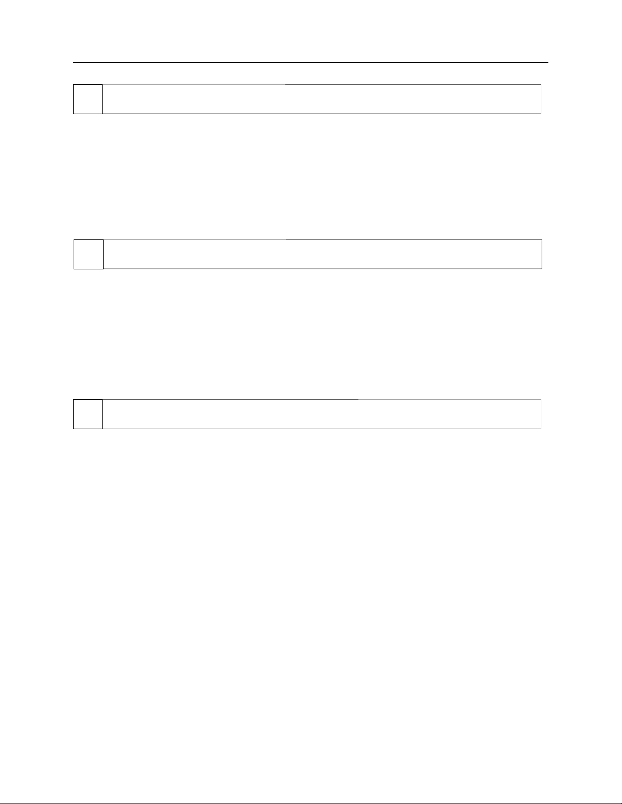
MINI MICR USB with 3-Track MSR
07 MISSING CHARACTERS
Possible causes for this problem are:
• Feeding the check - When feeding the check, make sure that the MICR line is at the bottom
and the printed side of the check is facing the MagTek logo on the MICR Reader.
Determine if any of the conditions described above are true:
◊ If yes, rectify and continue to step 02.
◊ If no, continue to step 08.
08 COMMUNICATION PARAMETERS DO NOT MATCH
Verify that the communication parameters of the MICR Reader match the parameters of the PC.
Use MICRbase to verify/change the communication parameters.
Determine if the condition described above is true:
◊ If yes, rectify and continue to step 02.
◊ If no, continue to step 14.
09 INCORRECT FORMAT
Possible causes for this problem are:
• Incorrect Format Number - the current Check data format in the MICR Reader is not the
desired format. Use MICRbase to verify/change the format.
• Incorrect Message Format - the current Message format in the MICR Reader is not the
desired format. Use MICRbase to verify/change the Message format.
Determine if any of the conditions described above are true:
◊ If yes, rectify and continue to step 02.
◊ If no, continue to step 17.
44
Page 53
Appendix C. Troubleshooting Guide
10 PATH IS OBSTRUCTED
Foreign debris is obstructing the check path:
• Loose debris - power off the MICR Reader and try to push out any loose debris on the check
path. Grab the cleaning card and force it through the check path (this is a manual process, the
motor will not turn on). Try this procedure several times until the debris comes out. Power
on the MICR Reader.
• Wedged debris - the debris is wedged in and cannot be removed with the procedure described
above.
Is the foreign debris removable?
◊ if yes, remove and continue to step 02.
◊ If no, continue to step 17.
11 MOTOR SENSOR IS BLOCKED
The Motor sensor may be blocked by dust build-up or foreign debris (see Figure C-1). Use
forced air to clean the sensor.
Power off the MICR Reader and then power on again, observe the LED indicator:
◊ If the LED indicator blinks red, continue to step 17.
◊ Any other LED indicator status, continue to step 00.
12 EMF NOISE/INTERFERENCE
When idle, if EMF detect is set to YES (see HW Command, Section 4), the MICR Reader
monitors the signal coming from the MICR head. If any signal (noise/interference) with
amplitude large enough to affect check reading is detected, the LED indicator blinks red/green.
Possible sources of EMF are monitors, AC adapters, or magnetic devices. Set EMF to NO, or
move the MICR Reader at least 6 inches away from the source of noise/interference.
Determine if the condition described above is true:
◊ If yes, rectify and continue to step 00.
◊ If no, continue to step 13.
45
Page 54

MINI MICR USB with 3-Track MSR
13 DATA SENSOR IS BLOCKED
The data sensor may be blocked (see Figure C-1). Try one or both of the following procedures:
• Forced air - use forced air to clean the sensor.
• Cleaning card - power off the MICR Reader and try to push out any loose debris on the
check path. Grab the cleaning card and force it through the check path (this is a manual
process, the motor will not turn on). Try this procedure several times until the debris comes
out.
Power off the MICR Reader and then power on again, observe the LED indicator:
◊ If the LED indicator blinks red/green, continue to step 17.
◊ Any other LED indicator status, continue to step 00.
◊
14 NO MICR DATA DETECTED
Possible causes for this problem are:
• No MICR characters - the ink used to print the MICR characters does not have magnetic
properties. Try one of the sample checks provided by MagTek.
• Feeding the check - When feeding the check, make sure that the MICR line is at the bottom
and the printed side of the check is facing the MagTek logo on the MICR Reader.
Determine if any of the conditions described above are true:
◊ If yes, rectify and continue to step 02.
◊ If no, continue to step 14.
15 CABLE PROBLEM
Possible causes for this problem are:
• Loose connection - the cable connector on the PC or the MICR Reader may be loose. Make
sure that both connectors are tightly connected.
• Damaged cable - the connectors, pins or wires in the cable may be damaged. Replace cable.
Determine if any of the conditions described above are true:
◊ If yes, rectify and continue to step 02.
◊ If no, continue to step 17.
46
Page 55

Appendix C. Troubleshooting Guide
16 NO PROBLEM FOUND
The MICR Reader is operating properly. If you have additional concerns or requirements please
contact your MagTek representative.
17 READ INSTA-CHANGE CHECK
Read Insta-Change check with the appropriate settings. Return to step 00. If condition persists,
continue to step 18.
18 RETURN MICR READER TO MAGTEK
The MICR Reader has a problem that needs further analysis, testing, and possibly repair. Please
contact the MagTek Help Desk at (888) 624-8350, and make arrangements to send the unit back
to MagTek. Include a detailed description of the problem.
↑
Motor Sensor Data Sensor →
Figure C-1. Sensor Location
47
Page 56

MINI MICR USB with 3-Track MSR
48
Page 57

APPENDIX D. ASCII CODES
The following is a listing of the ASCII (American Standard Code for Information Interchange)
codes. ASCII is a 7-bit code, which is represented here with a pair of hexadecimal digits.
ASCII Hex Dec ASCII Hex Dec ASCII Hex Dec ASCII Hex Dec
NUL 00 0 SP 20 32 @ 40 64 ` 60 96
SOH 01 1 ! 21 33 A 41 65 a 61 97
STX 02 2 " 22 34 B 42 66 b 62 98
ETX 03 3 # 23 35 C 43 67 c 63 99
EOT 04 4 $ 24 36 D 44 68 d 64 100
ENQ 05 5 % 25 37 E 45 69 e 65 101
ACK 06 6 & 26 38 F 46 70 f 66 102
BEL 07 7 ' 27 39 G 47 71 g 67 103
BS 08 8 ( 28 40 H 48 72 h 68 104
HT 09 9 ) 29 41 I 49 73 i 69 105
LF 0A 10 * 2A 42 J 4A 74 j 6A 106
VT 0B 11 + 2B 43 K 4B 75 k 6B 107
FF 0C 12 , 2C 44 L 4C 76 l 6C 108
CR 0D 13 - 2D 45 M 4D 77 m 6D 109
SO 0E 14 . 2E 46 N 4E 78 n 6E 110
SI 0F 15 / 2F 47 O 4F 79 o 6F 111
DLE 10 16 0 30 48 P 50 80 p 70 112
DC1 11 17 1 31 49 Q 51 81 q 71 113
DC2 12 18 2 32 50 R 52 82 r 72 114
DC3 13 19 3 33 51 S 53 83 s 73 115
DC4 14 20 4 34 52 T 54 84 t 74 116
NAK 15 21 5 35 53 U 55 85 u 75 117
SYN 16 22 6 36 54 V 56 86 v 76 118
ETB 17 23 7 37 55 W 57 87 w 77 119
CAN 18 24 8 38 56 X 58 88 x 78 120
EM 19 25 9 39 57 Y 59 89 y 79 121
SUB 1A 26 : 3A 58 Z 5A 90 z 7A 122
ESC 1B 27 ; 3B 59 [ 5B 91 { 7B 123
FS 1C 28 < 3C 60 \ 5C 92 | 7C 124
GS 1D 29 = 3D 61 ] 5D 93 } 7D 125
RS 1E 30 > 3E 62 ^ 5E 94 ~ 7E 126
US 1F 31 ? 3F 63 _ 5F 95 DEL 7F 127
49
Page 58

MINI MICR USB with 3-Track MSR
50
 Loading...