

Page 1

MICRSAFE
TECHNICAL REFERENCE MANUAL
Manual Part Number: 99875466-3
OCTOBER 2010
REGISTERED TO ISO 9001:2008
1710 Apollo Court
Seal Beach, CA 90740
Phone: (562) 546-6400
FAX: (562) 546-6301
Technical Support: (651) 415-6800
www.magtek.com
Page 2

ii
Copyright© 2002-2010
Rev
Date
Notes
1.01
Mar 3, 2010
Initial Release
2.01
Aug 27, 2010
Updated images; change AC to DC; updated
command information
3.01
Oct 20, 2010
Noted configuration 8.3; In troubleshooting
Removed 08 from troubleshooting guide
MagTek® Inc.
Printed in the United States of America
Information in this document is subject to change without notice. No part of this document may be
reproduced or transmitted in any form or by any means, electronic or mechanical, for any purpose,
without the express written permission of MagTek, Inc.
MagTek is a registered trademark of MagTek, Inc.
REVISIONS
guide changed18 “Return MICRSAFE to
MagTek” to “Return MICRSAFE for service”;
Page 3

iii
LIMITED WARRANTY
MagTek warrants that the products sold pursuant to this Agreement will perform in accordance with MagTek’s
published specifications. This warranty shall be provided only for a period of one year from the date of the
shipment of the product from MagTek (the “Warranty Period”). This warranty shall apply only to the “Buyer”
(the original purchaser, unless that entity resells the product as authorized by MagTek, in which event this
warranty shall apply only to the first repurchaser).
During the Warranty Period, should this product fail to conform to MagTek’s specifications, MagTek will, at its
option, repair or replace this product at no additional charge except as set forth below. Repair parts and
replacement products will be furnished on an exchange basis and will be either reconditioned or new. All
replaced parts and products become the property of MagTek. This limited warranty does not include service to
repair damage to the product resulting from accident, disaster, unreasonable use, misuse, abuse, negligence, or
modification of the product not authorized by MagTek. MagTek reserves the right to examine the alleged
defective goods to determine whether the warranty is applicable.
Without limiting the generality of the foregoing, MagTek specifically disclaims any liability or warranty for
goods resold in other than MagTek’s original packages, and for goods modified, altered, or treated without
authorization by MagTek.
Service may be obtained by delivering the product during the warranty period to MagTek (1710 Apollo Court,
Seal Beach, CA 90740). If this product is delivered by mail or by an equivalent shipping carrier, the customer
agrees to insure the product or assume the risk of loss or damage in transit, to prepay shipping charges to the
warranty service location, and to use the original shipping container or equivalent. MagTek will return the
product, prepaid, via a three (3) day shipping service. A Return Material Authorization (“RMA”) number must
accompany all returns. Buyers may obtain an RMA number by contacting Technical Support at (888) 624-8350.
EACH BUYER UNDERSTANDS THAT THIS MAGTEK PRODUCT IS
OFFERED AS IS.
MAGTEK MAKES NO OTHER WARRANTY, EXPRESS OR
IMPLIED, AND MAGTEK DISCLAIMS ANY WARRANTY OF ANY OTHER
KIND, INCLUDING ANY WARRANTY OF MERCHANTABILITY OR FITNESS
FOR A PARTICULAR PURPOSE.
IF THIS PRODUCT DOES NOT CONFORM TO MAGTEK’S SPECIFICATIONS, THE SOLE REMEDY
SHALL BE REPAIR OR REPLACEMENT AS PROVIDED ABOVE. MAGTEK’S LIABILITY, IF ANY,
SHALL IN NO EVENT EXCEED THE TOTAL AMOUNT PAID TO MAGTEK UNDER THIS
AGREEMENT. IN NO EVENT WILL MAGTEK BE LIABLE TO THE BUYER FOR ANY DAMAGES,
INCLUDING ANY LOST PROFITS, LOST SAVINGS, OR OTHER INCIDENTAL OR CONSEQUENTIAL
DAMAGES ARISING OUT OF THE USE OF, OR INABILITY TO USE, SUCH PRODUCT, EVEN IF
MAGTEK HAS BEEN ADVISED OF THE POSSIBILITY OF SUCH DAMAGES, OR FOR ANY CLAIM BY
ANY OTHER PARTY.
LIMITATION ON LIABILITY
EXCEPT AS PROVIDED IN THE SECTIONS RELATING TO MAGTEK’S LIMITED WARRANTY,
MAGTEK’S LIABILITY UNDER THIS AGREEMENT IS LIMITED TO THE CONTRACT PRICE OF THIS
PRODUCT.
MAGTEK MAKES NO OTHER WARRANTIES WITH RESPECT TO THE PRODUCT, EXPRESSED OR
IMPLIED, EXCEPT AS MAY BE STATED IN THIS AGREEMENT, AND MAGTEK DISCLAIMS ANY
IMPLIED WARRANTY, INCLUDING WITHOUT LIMITATION ANY IMPLIED WARRANTY OF
MERCHANTABILITY OR FITNESS FOR A PARTICULAR PURPOSE.
MAGTEK SHALL NOT BE LIABLE FOR CONTINGENT, INCIDENTAL, OR CONSEQUENTIAL
DAMAGES TO PERSONS OR PROPERTY. MAGTEK FURTHER LIMITS ITS LIABILITY OF ANY KIND
WITH RESPECT TO THE PRODUCT, INCLUDING ANY NEGLIGENCE ON ITS PART, TO THE
CONTRACT PRICE FOR THE GOODS.
MAGTEK’S SOLE LIABILITY AND BUYER’S EXCLUSIVE REMEDIES ARE STATED IN THIS SECTION
AND IN THE SECTION RELATING TO MAGTEK’S LIMITED WARRANTY.
Page 4

iv
FCC WARNING STATEMENT
This equipment has been tested and was found to comply with the limits for a Class B digital device pursuant to
Part 15 of FCC Rules. These limits are designed to provide reasonable protection against harmful interference
when the equipment is operated in a residential environment. This equipment generates, uses, and can radiate
radio frequency energy and, if not installed and used in accordance with the instruction manual, may cause
harmful interference with radio communications. However, there is no guarantee that interference will not occur
in a particular installation.
FCC COMPLIANCE STATEMENT
This device complies with Part 15 of the FCC Rules. Operation of this device is subject to the following two
conditions: (1) this device may not cause harmful interference, and (2) this device must accept any interference
received, including interference that may cause undesired operation.
CANADIAN DOC STATEMENT
This digital apparatus does not exceed the Class B limits for radio noise from digital apparatus set out in the
Radio Interference Regulations of the Canadian Department of Communications.
Le présent appareil numérique n’émet pas de bruits radioélectriques dépassant les limites applicables aux
appareils numériques de la classe B prescrites dans le Réglement sur le brouillage radioélectrique édicté par le
ministère des Communications du Canada.
This Class B digital apparatus complies with Canadian ICES-003.
Cet appareil numériqué de la classe B est conformé à la norme NMB-003 du Canada.
CE STANDARDS
Testing for compliance with CE requirements was performed by an independent laboratory. The unit under test
was found compliant with standards established for Class B devices.
UL/CSA
This product is recognized per Underwriter Laboratories and Canadian Underwriter Laboratories 1950.
RoHS STATEMENT
When ordered as RoHS compliant, this product meets the Electrical and Electronic Equipment (EEE) Reduction
of Hazardous Substances (RoHS) European Directive 2002/95/EC. The marking is clearly recognizable, either as
written words like “Pb-free”, “lead-free”, or as another clear symbol ( ).
Page 5

v
Contents
SECTION 1. OVERVIEW ............................................................................................................................. 1
FEATURES ............................................................................................................................................... 2
ACCESSORIES ......................................................................................................................................... 2
SOFTWARE DRIVERS REQUIRED ......................................................................................................... 2
REFERENCE DOCUMENTS .................................................................................................................... 3
SPECIFICATIONS..................................................................................................................................... 3
SECTION 2. INSTALLATION....................................................................................................................... 5
REQUIREMENTS...................................................................................................................................... 5
PROCEDURE ............................................................................................................................................ 5
USB DRIVER INSTALLATION (WINDOWS) ............................................................................................ 6
SECTION 3. OPERATION ........................................................................................................................... 7
CHECK READING PROCEDURE............................................................................................................. 7
CARD SWIPE PROCEDURE .................................................................................................................... 7
LED INDICATORS .................................................................................................................................... 8
SECTION 4. LEGACY COMMANDS ........................................................................................................... 9
INSTA-CHANGE CHECKS ....................................................................................................................... 9
MICRBASE SETUP PROGRAM FOR WINDOWS ................................................................................... 9
COMMAND FORMAT ............................................................................................................................. 10
SWB - SWITCH B COMMAND ............................................................................................................... 11
SWB PARAMETERS .............................................................................................................................. 12
Control Characters and MICR Data .................................................................................................... 12
Control Characters and Card Data...................................................................................................... 12
Communication Modes ....................................................................................................................... 12
Send Data After Error .......................................................................................................................... 13
Send Status After Data ....................................................................................................................... 13
SWC - SWITCH C COMMAND ............................................................................................................... 14
SWC PARAMETERS .............................................................................................................................. 15
CMC-7 Character Set .......................................................................................................................... 15
Invalid Command Response ............................................................................................................... 15
Data Header ........................................................................................................................................ 16
Card Data Message ............................................................................................................................ 16
HW - HARDWARE COMMAND .............................................................................................................. 16
HW PARAMETERS ................................................................................................................................. 17
Disable/Enable Tracks ........................................................................................................................ 17
ID Card Decoding ................................................................................................................................ 17
EMF Detect ......................................................................................................................................... 17
FC - FORMAT CHANGE COMMAND ..................................................................................................... 18
VR - VERSION COMMAND .................................................................................................................... 18
SA - SAVE COMMAND ........................................................................................................................... 18
RS - RESET COMMAND ........................................................................................................................ 18
DM – DISABLE MICR COMMAND .......................................................................................................... 19
EM – ENABLE MICR COMMAND ........................................................................................................... 19
KS – ENABLE KEYSTROKE COMMAND ............................................................................................... 19
SLP – SLEEP MODE COMMAND .......................................................................................................... 19
RD – ENABLE AUXILIARY PORT COMMAND ...................................................................................... 19
CHKCNT – CHECK COUNT COMMAND ............................................................................................... 20
SECTION 5. USB COMMUNICATIONS .................................................................................................... 21
HOST APPLICATIONS ........................................................................................................................... 21
CARD AND MICR DATA ......................................................................................................................... 22
PROGRAMMABLE CONFIGURATION OPTIONS ................................................................................. 22
LOW LEVEL COMMUNICATIONS ......................................................................................................... 22
HID USAGES .......................................................................................................................................... 23
REPORT DESCRIPTOR ......................................................................................................................... 23
COMMANDS ........................................................................................................................................... 24
COMMAND PROCESSING..................................................................................................................... 25
COMMAND NUMBER ............................................................................................................................. 25
DATA LENGTH ....................................................................................................................................... 25
Page 6

vi
DATA ....................................................................................................................................................... 25
RESULT CODE ....................................................................................................................................... 26
GET AND SET PROPERTY COMMANDS ............................................................................................. 26
SOFTWARE ID PROPERTY .................................................................................................................. 27
SERIAL NUM PROPERTY ...................................................................................................................... 28
POLLING INTERVAL PROPERTY ......................................................................................................... 29
TRACK DATA SEND FLAGS PROPERTY ............................................................................................. 29
ASCII TO KEYPRESS CONVERSION TYPE PROPERTY .................................................................... 30
ACTIVE KEYMAP PROPERTY ............................................................................................................... 32
CONVERT FROM CHAR A PROPERTY ................................................................................................ 33
CONVERT TO STRING A PROPERTY .................................................................................................. 34
CONVERT FROM CHAR B PROPERTY ................................................................................................ 34
CONVERT TO STRING B PROPERTY .................................................................................................. 35
RESET DEVICE COMMAND .................................................................................................................. 36
GET KEYMAP ITEM COMMAND............................................................................................................ 37
SET KEYMAP ITEM COMMAND ............................................................................................................ 38
SAVE CUSTOM KEYMAP COMMAND .................................................................................................. 40
SEND LEGACY COMMAND COMMAND ............................................................................................... 40
SECTION 6. ENCRYPTION ....................................................................................................................... 43
APPENDIX A. FORMAT LIST .................................................................................................................... 45
APPENDIX B. CHECK READING ............................................................................................................... 49
E13-B CHARACTER SET ....................................................................................................................... 49
CMC-7 CHARACTER SET ...................................................................................................................... 49
CHECK LAYOUTS .................................................................................................................................. 50
MICR FIELDS .......................................................................................................................................... 51
1-Transit Field ..................................................................................................................................... 51
2-On-Us Field ...................................................................................................................................... 51
3-Amount Field .................................................................................................................................... 52
4-Auxiliary On-Us Field ....................................................................................................................... 52
APPENDIX C. TROUBLESHOOTING GUIDE ........................................................................................... 53
REQUIREMENTS.................................................................................................................................... 53
SET-UP ................................................................................................................................................... 53
00 CHECK LED ............................................................................................................................... 53
01 CHECK THE POWER TO THE MICRSAFE .............................................................................. 54
02 READ A CHECK ......................................................................................................................... 54
03 DID PC RECEIVE DATA? .......................................................................................................... 54
04 ANALYZE DATA ......................................................................................................................... 54
05 VERIFY PARAMETERS ............................................................................................................. 55
06 READ ERROR............................................................................................................................ 55
07 MISSING CHARACTERS .......................................................................................................... 55
09 INCORRECT FORMAT .............................................................................................................. 56
10 PATH IS OBSTRUCTED ............................................................................................................ 56
11 MOTOR SENSOR IS BLOCKED ............................................................................................... 57
12 EMF NOISE/INTERFERENCE ................................................................................................... 57
13 DATA SENSOR IS BLOCKED ................................................................................................... 57
14 NO MICR DATA DETECTED ..................................................................................................... 58
15 CABLE PROBLEM ..................................................................................................................... 58
16 NO PROBLEM FOUND .............................................................................................................. 58
17 READ INSTA-CHANGE CHECK ................................................................................................ 58
18 RETURN MICRSAFE FOR SERVICE ....................................................................................... 59
APPENDIX D. ASCII CODES ..................................................................................................................... 61
APPENDIX E. USAGE ID DEFINITIONS ................................................................................................... 63
APPENDIX F. MODIFIER BYTE DEFINITIONS ........................................................................................ 71
Page 7

vii
FIGURES and TABLES
Figure 1-1. MICRSafe with 3-Track MSR ...................................................................................................viii
Table 1-1. Specifications .............................................................................................................................. 3
Figure 3-1. Check Orientation ....................................................................................................................... 7
Table 3-1. LED indicators ............................................................................................................................. 8
Table 4-2. SWB Command......................................................................................................................... 11
Table 4-3. Control Characters .................................................................................................................... 12
Table 4-4. Error and Status Codes ............................................................................................................. 13
Table 4-5. SWC Command ........................................................................................................................ 14
Table 4-6. HW Command ........................................................................................................................... 17
Table B-1. CMC-7 Nonnumeric Characters ................................................................................................ 50
Figure B-1. Personal Checks ...................................................................................................................... 50
Figure B-2. Business Checks ..................................................................................................................... 51
Figure C-1. Sensor Location ....................................................................................................................... 59
Table E-1. Keyboard/Keypad ...................................................................................................................... 63
Table F-1. Modifier Byte .............................................................................................................................. 71
Page 8
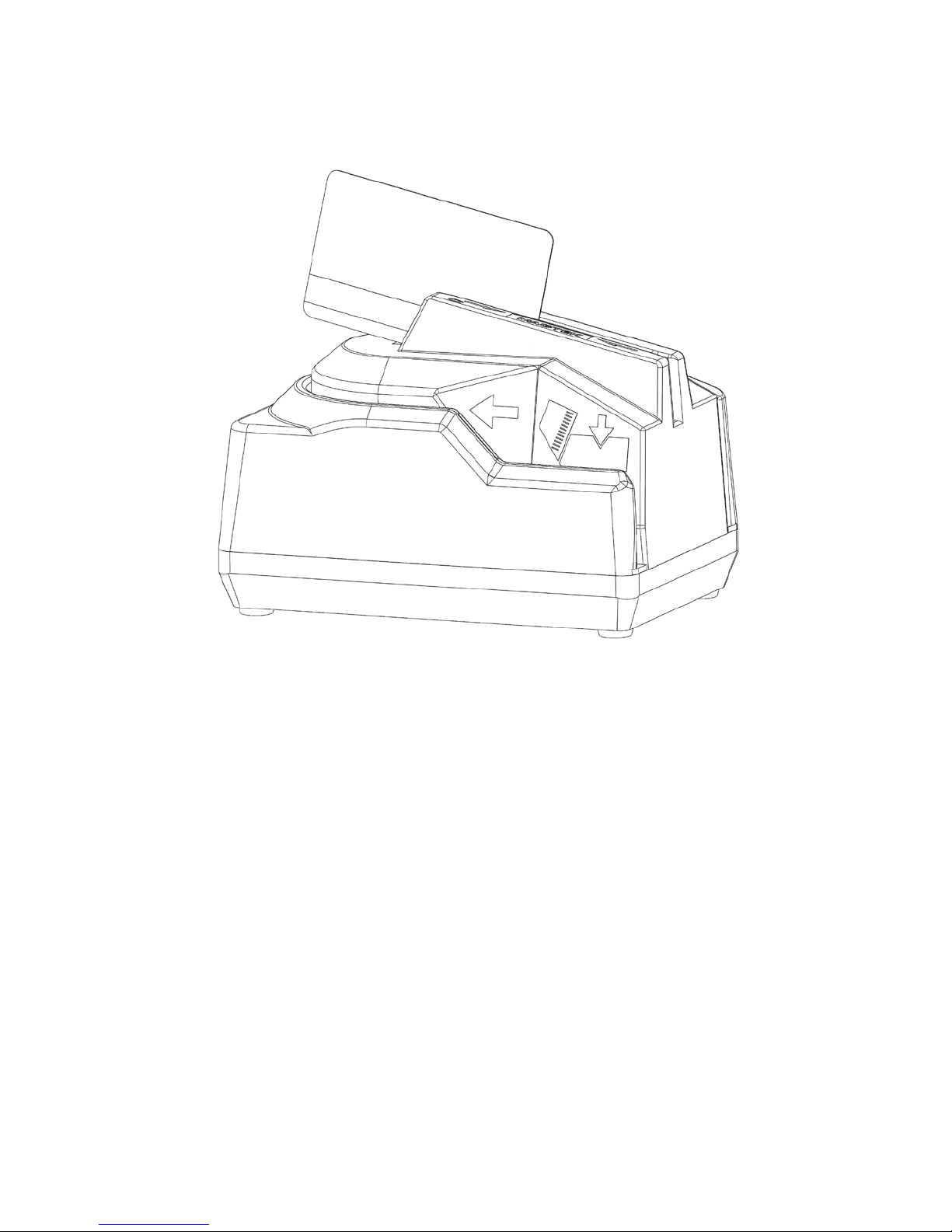
viii
Figure 1-1. MICRSafe with 3-Track MSR
Page 9

SECTION 1. OVERVIEW
The MICRSafe with 3-Track MSR is both a MICR (Magnetic Ink Character Recognition) Check
Reader and an MSR (Magnetic Stripe Reader).
The MICRSafe, in a typical application, reads the magnetic data encoded on the bottom of
checks or on magnetic stripe cards and transmits this data to a Host device. The Host device then
uses a specific authorization or verification process to validate a business transaction.
The use of the MICRSafe improves accuracy and speed because there is no manual data entry;
therefore there are no keying errors or unwanted delays.
The MICRSafe has three interface capabilities. First, the MICRSafe can communicate with the
Host system using a standard USB interface. The driver will emulate a serial port on the host
PC. All data is transmitted as ASCII characters (See Appendix D). This is MICRSafe VCOM
unit.
Second, the MICRSafe can emulate a USB keyboard. This device is compatible with PCs or
hosts that support USB keyboards. The Reader emulates a USB Human Interface Device (HID)
United States keyboard or optionally all international keyboards using ALT ASCII code keypad
key combinations or customizable key maps. This allows host applications designed to acquire
card data from keyboard input to seamlessly acquire the card data from the reader. This is
MICRSafe HID unit.
Caution
If another keyboard is connected to the same host as this device and a
key is pressed on the other keyboard while this device is transmitting,
then the data transmitted by this device may get corrupted.
Because of potential “data interleave” issues associated with the USB Keyboard interface,
MagTek recommends that this product should only be used if the application requires data to be
provided via the keyboard input.
Third, the MICRSafe can communicate with a device other than the host, for instance a POS
terminal, through an auxiliary RS-232 interface. All data is transmitted as ASCII characters (See
Appendix D). The MICRSafe has the capability of supporting some hardware handshaking
signals. (See Section 4, Legacy Commands.) Depending on POS connection port, a ‘Mini DIN 9
Pin’ or a ‘DB9’ cable can be used to connect. Communication in this mode is one-way only,
outputting data from the MICRSafe to POS terminal. Baudrate is always set to 9600 bps.
1
Page 10

MICRSafe with 3-Track MSR
2
FEATURES
• This device incorporates a MICR Reader with a 3-Track MagneSafe MSR.
• The three track MSR autodiscriminates different card formats: ISO (International Standards
Organization), CDL (California Drivers License), or AAMVA (American Association of
Motor Vehicle Administrators).
• Small footprint.
• Automatic parsing of MICR fields: transit, account, etc.
• Extensive list of formats to transmit MICR data.
• Optional error/status reporting for check reading.
• Optional TDES DUKPT encryption of MICR and Card data.
• Reads E13-B and CMC-7 MICR fonts.
• Automatically goes into sleep mode when not in use; meets EnergyStar requirements.
• EMF noise detection
• Compatible with USB specification Revisions 2.0 and 1.1
• Compatible with HID specification Versions 2.0 and 1.1
• USB communications with the host may occur via a Virtual COM port or by HID/keyboard
emulation.
• Communications with third party systems may occur via an auxiliary RS-232 interface or
using standard Windows HID drivers. No third party device driver is required.
ACCESSORIES
Accessories available for the MICRSafe are as follows:
• Standard USB cable, Part Number 22553301
• Optional auxiliary RS-232 cable, Part Number 22517584 /22517509
• DC Power Adapter with Cable, 120VAC to 12 VDC, 1 Amp, Part Number 64300118
(64300121 for international customers)
• MICR Reader Cleaning Card, Part Number 96700006
• Sample Checks, Part Number 96530005
• MICRbase Setup Program, Part Number 22000021
SOFTWARE DRIVERS REQUIRED
If you are using the HID unit, the standard HID and Keyboard drivers that come with an
operating system are usually all that is needed. For example, the Windows operating system
provides all the drivers needed to communicate to the device, unless you requested that the
factory configure your MICRSafe device(s) to use a VCOM port. In that case, you would need to
download the VCOM driver from the MagTek website. This driver allows a USB device such as
the MICRSafe to appear as an additional COM port available to the PC, enabling application
software to access the USB device as if it were connected via a standard COM (RS-232) port.
Page 11

Section 1. Overview
3
OPERATING
Reference Standards
ISO/CDL/AAMVA
Power Input
120 VAC, 50/60 Hz
Output Signal Levels
12 VDC, 200 mA (Idle), 600mA (Operating)
Check Read/Decode/Transit
Time
2 second
CMC-7
MSR supported
Tracks 1, 2, and 3
MECHANICAL
Dimensions
Length 6.25”, Width 4.0”, Height 4.25”
Weight:
3.0 lbs. MSR and Adapter included
Cable length
6’
Connectors
USB Type B connector
ENVIRONMENTAL
Temperature
Operating
0oC to 50oC (32oF to 122oF)
Storage
-30oC to 60oC (-22oF to 140oF)
Humidity
Operating
10% to 90% noncondensing
Storage
Up to 95% noncondensing
REFERENCE DOCUMENTS
Axelson, Jan. USB Complete, Everything You Need to Develop Custom USB Peripherals, 1999.
Lakeview Research, 2209 Winnebago St., Madison WI 53704, 396pp., http://www.lvr.com
MICRbase setup program for MICR readers Software and Operation P/N 99875102USB Human
Interface Device (HID) Class Specification Version 1.1
Universal Serial Bus (USB): HID Usage Tables Version 1.12 (1/21/2005)
USB (Universal Serial Bus) Specification, Version 1.1, Copyright© 1998 by Compaq Computer
Corporation, Intel Corporation, Microsoft Corporation, NEC Corporation
USB Implementers Forum, Inc., www.usb.org
ANS X9.24-2004 Retail Financial Services Symmetric Key Management Part 1: Using
Symmetric Techniques
SPECIFICATIONS
Table 1-1 lists the specifications for the MICRSafe device:
Table 1-1. Specifications
MICR fonts supported E13-B
Mini Din-9 male,
Page 12

MICRSafe with 3-Track MSR
4
Page 13

SECTION 2. INSTALLATION
The installation for the MICRSafe is as follows:
REQUIREMENTS
The following is required for the Installation:
• MICRSafe Device, Part Number 22551001 (VCOM) or 22551002(HID)
• Standard USB cable, Part Number 22553301
• Optional auxiliary RS-232 cable, Part Number 22517584
• DC Power Adapter with Cable, 120VAC to 12 VDC, 1 Amp, Part Number 64300118
(64300121 for international customers)
• MICRbase software, included in the CD Package Part Number 30037855, or can be
downloaded from: http://www.magtek.com/support/software/demo_programs/ under
‘MICRbase Setup Program
• VCOM Driver for MICRSAFE, included in the CD Part Number 30037903 or can be
downloaded from: http://www.magtek.com/support/software/programming_tools/, under
‘MICRSafe VCOM’.
PROCEDURE
Perform the following steps:
1. Connect the interface cable’s USB A connector to the PC.
2. Connect the interface cable’s USB B connector to the MICRSafe.
3. Connect the DC power adapter’s jack to the plug on the MICRSafe.
4. Connect the DC power adapter’s plug to the wall outlet.
5. The first time the Reader is connected to the PC, Windows will need to install the USB
driver. See the instructions below.
6. The LED indicator on the MICRSafe should turn on to a steady green. The LED indicator is
located to the left of the slot where the check is first inserted for reading.
Do not place the MICRSafe within 6 inches of a computer
monitor or power supply. These devices may cause undesirable
interference with the check reading operation.
’
Caution
5
Page 14

MICRSafe with 3-Track MSR
6
USB DRIVER INSTALLATION (WINDOWS)
On hosts with the Windows operating system, the first time the MICRSafe is plugged into a
specific USB port, Windows will open a dialog box which will guide you through the process of
installing a driver for the device; follow the instructions given in the dialog box. Windows will
install the driver that is used for HID keyboard devices; this driver is a basic component of all
modern versions of the Windows operating system. Sometimes, Windows will find all the files it
needs. Other times, Windows will need to know the location of the files it needs. If Windows
prompts for the file locations, insert the CD that was used to install Windows on your PC and
point Windows to the CD’s root directory. Windows should find all the files it needs there.
Once completed, the driver installation process described above will not recur unless the device
is subsequently plugged into a different USB port. After this installation, the device can
communicate with user’s application programs such as MICRbase (P/N 22000021) to read
checks, credit cards and setup configurations.
Page 15
SECTION 3. OPERATION
This section contains check and card reading procedures and LED indicator states.
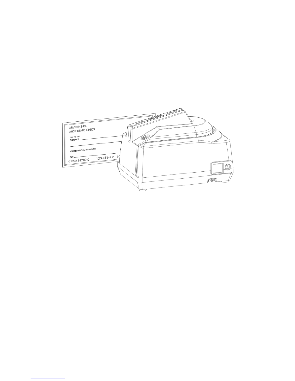
CHECK READING PROCEDURE
1. Orient the check so the MICR line is down and the printed side faces the center of the
MICRSafe as shown in Figure 3-1.
Figure 3-1. Check Orientation
2. Drop the check so the leading edge is in the open slot.
3. When the MICRSafe detects the presence of the check, the motor will turn on. At this
time, gently urge the check forward until the unit grabs the check. When this happens,
release the check. The check will then be transported around the check path and will exit
through the other side.
4. After the check is read, the MICRSafe will transmit the data as specified by the
parameters described in Section 4, Commands.
CARD SWIPE PROCEDURE
The card may be swiped through the MSR in either direction, but the magnetic stripe must be
oriented in only one direction as shown in Figure 1-1. The MSR will transmit raw card data (“as
is” on the card) for all tracks that have been enabled using the HW (Hardware) command
(Section 4, Legacy Commands
7
Page 16

MICRSafe with 3-Track MSR
8
LED INDICATOR
DESCRIPTION
OFF
Power off
SOLID GREEN
Ready to read check or card
OFF→ SOLID RED
Check or card read error
OFF→ SOLID GREEN
Good read
FLASH RED/GREEN
Data sensor blocked (motor does not run)*
FLASH RED
Motor sensor blocked (motor does not run)*
The MSR is capable of reading ISO, AAMVA, and CDL encoded cards. The MSR will
autodiscriminate all the card formats when the ID Card Decoding option is enabled using the HW
(Hardware) command (Section 4, Legacy Commands).
LED INDICATORS
Table 3-1 describes the LED indicator conditions for check and card reading operations. The
LED indicator for check reading is located to the left of the slot where the check is first inserted
for reading. The LED indicator for card reading is located on the upper left side of the MSR rail.
Table 3-1. LED indicators
*Refer to Appendix C. Troubleshooting Guide.
Page 17

SECTION 4. LEGACY COMMANDS
This section describes the use of commands and programmable options available for the
MICRSafe.
Note
All options described below can be factory set as specified by the
user when ordering.
You may use either of two methods to execute the MICRSafe commands: Insta-Change checks
or the MICRbase Setup Program for Windows (see *NOTE below).
INSTA-CHANGE CHECKS
The first method is the use of Insta-Change checks, which is a more practical way of setting
up the MICRSafe for most applications. The Insta-Change check is a MICR encoded
document that contains commands and options used to reset the parameters of the MICR
Reader. Multiple commands and options may be contained on one Insta-Change check.
When used, the Insta-Change checks are run through the MICRSafe the same as a standard
check, and the options to be used are automatically selected. To obtain Insta-Change checks,
notify a MagTek representative and specify what options will be used. To operate InstaChange checks, install the MICRSafe as described in Section 2 and watch the LED indicator.
When the Insta-Change check is run through the MICRSafe and read successfully, the LED
indicator will blink green. If the LED indicator turns red, the read was not successful. If the
LED is blinking red and green, the Insta-Change check contains an invalid format. Try again
or use a different Insta-Change check.
MICRBASE SETUP PROGRAM FOR WINDOWS
The MICRbase program (P/N 22000021) allows the user to control all the programmable
options available in the MICRSafe. *NOTE: MICRbase version 8.3 or newer will work
with this device in either configuration. If the MICRSafe model used is a Keyboard
Emulation HID device, you may also program the device using the USB Swipe and Insert
Reader demo (version 1.08 or newer). For details on this usage see the USB
Communications section (section 5) of this manual.
The program provides a graphical, user-friendly interface that hides the complexities
involved in manually entering MICR commands. The user is no longer required to know the
specific commands or the detailed data associated with each command. However, the
program still allows manual entry of commands for advanced users, and it also displays data
from cards and checks that are read. If your MICRSafe is using a VCOM port,; the legacy
MICR commands found in this section may be sent to the device exactly as described below.
However, if your MICRSafe is using an HID interface, you must send the legacy MICR
commands to the device using the “Send Legacy Command”, details of which can be found
in the “USB Communications” section of this manual. For details and examples of how to
use MICRbase see P/N 99875102. For more detailed information also refer to the
Readme.txt file that comes with this program. You can download the MICRbase program
from the Internet at http://www.magtek.com/support/software/demo_programs/ under
‘MICRbase Setup Program’
9
Page 18

MICRSafe with 3-Track MSR
COMMAND FORMAT
You must use the following format when entering the commands manually:
• [COMMAND][DATA]<CR>
where:
• [COMMAND] is a string of alpha characters (usually 2 or 3 bytes in length).
• [Data] is optional as described below for each command.
• <CR> is always required.
• All characters are ASCII.
• No spaces, brackets, or angle brackets required.
If your MICRSafe is using an HID Keyboard Emulation interface, then all legacy MICR
commands found in this section must be sent to the device using the “Send Legacy Command”
Command. Details of this command can be found in the “USB Communications” section of this
manual.
10
Page 19

Section 4. Legacy Commands
BIT
PARAMETERS
7
6
5
4
3
2
1
0
0
<LF>: No
1
<LF>: Yes
0 <CR>: No
1 <CR>: Yes
0
<ETX>: No
1
<ETX>: Yes
0 <ESC>: No
1 <ESC>: Yes
0
<STX>: No
1
<STX>: Yes
0 Send Data After Error?: No
1 Send Data After Error?: Yes
0
Send Status After Data?: No
1
Send Status After Data?: Yes
0 0 0 0 0 0 Comm Mode: 0 - Data Only
1 0 0 0 0 0 Comm Mode: 1 - Data<CR>
0 0 0 0 0 1 Comm Mode: 2 - Data<LF>
0 0 0 0 1 1 Comm Mode: 3 - Data<CR><LF>
0 0 1 0 0 0 Comm Mode: 4 - <ESC>Data
0 0 1 0 1 0 Comm Mode: 5 - <ESC>Data<CR>
0 1 0 1 0 0 Comm Mode: 6 - <STX>Data<ETX>
1 0 0 0 0 1 Comm Mode: 7 - <STX>Data<ETX><LRC>
0 1 1 1 1 1 Comm Mode- 8 – All controls
0 0 0 1 0 1 Comm Mode- 9- Data<ETX><LF>
0 1 0 0 1 0 Comm Mode- 10- <STX>Data<CR>
SWB - SWITCH B COMMAND
The SWB command controls the message format, shown in Table 4-2. The data for this
command consists of 8 ASCII bits (“0” = hex 30 and “1” = hex 31).
To execute, send the SWB command as follows:
SWB01010101<CR> (with data)
or
SWB<CR> (without data)
When sending data, all 8 bits must be provided. The MICRSafe will execute the
command but it will not reply. The new settings become effective immediately. To make
this command permanent, use the command SA (Save) described at the end of this
section.
If no data is sent, the MICRSafe responds with the current settings for SWB.
Table 4-2. SWB Command
11
Page 20

MICRSafe with 3-Track MSR
CHARACTER
DESCRIPTION
HEX VALUE
<STX>
Start of Text
02
<ESC>
Escape
1B
<ETX>
End of Text
03
<CR>
Carriage Return
0D
<LF>
Line Feed
0A
SWB PARAMETERS
The SWB functions are listed in Table 4-2 above and are described below:
Control Characters and MICR Data
Control Characters may be added to MICR Data messages. The MICRSafe will insert
any control characters selected using this command into outgoing formatted MICR Data
messages in the following sequence:
<STX> <ESC> data <ETX> <CR> <LF>
The control characters, descriptions, and hex values are shown in Table 4-3.
Table 4-3. Control Characters
CONTROL
For example, if the <STX> and <CR> options are set to YES, a MICR Data message
from the MICRSafe will look like this:
MICR Data: <STX>data<CR>
Control Characters and Card Data
If the card reader’s head is set to security level 2, then the same control characters may
also be added to Card Data messages, but they are applied to each track individually. For
example, if the <STX> and <ETX> options are set to YES, a Card Data message from the
MICRSafe will look like this:
Card Data: <STX>[TK1 data]<ETX><STX>[TK2 data]<ETX><STX>[TK3
data]<ETX>
Please note again that card reader heads that are set to security level 1 and 3 do not support this control
characters.
Communication Modes
The selection of Comm modes is a quick way of selecting multiple Control Characters.
For instance, to send a carriage return/line feed pair after the data, you can specify Comm
Mode 3.
12
Page 21

Section 4. Legacy Commands
PRIORITY
CODE
TYPE
DESCRIPTION
9
01
Error
No MICR data: no transit and no account found
8
09
Status
Mexican check
7
08
Status
Canadian check
6
05
Error
Transit error: No transit, bad character, bad
length, bad check digit
5
07
Error
Account error: No account, bad character
4
04
Error
Check # error: Bad character in check number
4
04
Status
No check number
3
03
Status
Low MICR signal, good read
2
10
Status
Business check
1
11
Status
Amount field present
0
00
Status
Good read
Comm Mode 7, also known as Packet Mode, calculates an LRC (Longitudinal
Redundancy Check), and appends it to the data message. Also, if a <NAK> (hex 15)
character is received in this mode, the MICRSafe will resend the last message.
Send Data After Error
The Send Data After Error option specifies whether the MICRSafe will return data to the
Host after a read error. If YES is selected and the MICRSafe detects a read error, the
MICRSafe will still send the data back to the Host. If NO is selected and the MICRSafe
finds an error, it will discard the data and nothing will be sent. The error conditions are
listed in Table 4-4.
Send Status After Data
The Send Status After Data option causes the MICRSafe to append a two-digit
error/status code to the end of the MICR data. For most formats (See Appendix A), the
error/status code will always be preceded by a forward slash (/). The error/status codes
are listed in Table 4-4.
For example, if a Canadian check (code 08) is read and has no errors, and the MICR data
is “1234567890”, then the message from the MICRSafe will look like this:
MICR Data: 1234567890/08
The status code is always at the end of the data, not the end of the message. For example,
using the above conditions, with the message format set to send <STX> and <ETX>, the
message from the MICRSafe will look like this:
MICR Data: <STX>1234567890/08<ETX>
Table 4-4. Error and Status Codes
Notes:
• The LED indicator will turn red on all error conditions.
• The absence of a check number is not considered an error.
13
Page 22

MICRSafe with 3-Track MSR
BITS
PARAMETERS
7
6
5
4
3
2
1
0
0
CMC-7 Character Set: No
1
CMC-7 Character Set: Yes
0 0 Invalid Commands: ?<CR>
0 1 Invalid Commands : No Reply (Header
Required)*
1 0 Invalid Commands: No Reply (No Header
Required)
1 1 Ignore all Commands
0 Reserved
0 Data Header: No ¹
1 Data Header: Yes ¹
0 Card Data Message: Multiple ¹
1 Card Data Message: Single ¹
included.
• If a multiple error condition occurs, the error or status code with the highest priority is
reported.
• All unreadable MICR characters are transmitted as an “?” ASCII character (hex 3F), except
for Format 00xx (See Appendix A).
SWC - SWITCH C COMMAND
The SWC command controls miscellaneous functions, shown in Table 4-5. The data for
this command consists of 8 ASCII bits (“0” = hex 30 and “1” = hex 31).
To execute, send the SWC command as follows:
SWC01010101<CR> (with data)
or
SWC<CR> (without data)
When sending data, all 8 bits must be provided. The MICRSafe will execute the
command but it will not reply. The new settings become effective immediately. To make
this command permanent, use the SA (Save) command described at the end of this
section.
If no data is sent, the MICRSafe responds with the current settings for SWC.
Table 4-5. SWC Command
0 0 These bits are always set to 0 but must be
* ‘Header Required’ means all commands must be preceded by a GS character (Hex 1D).
¹ For the card data, this parameter does not apply to units with card reader head set to security level 1 or 3
14
Page 23

Section 4. Legacy Commands
SWC PARAMETERS
The SWC functions are listed in Table 4-5 above and are described below:
CMC-7 Character Set
If NO is selected, the MICRSafe will only read E13-B characters. When YES is selected,
the MICRSafe will read both CMC-7 and E13-B characters (see Appendix B). However,
the MICRSafe will only output raw data ("as is" on the check) for checks with CMC-7
characters.
Invalid Command Response
Invalid command response is the action the MICRSafe will take upon receipt of a
command it does not recognize. It can also be used to stop the MICRSafe from receiving
any more commands.
The first option “?<CR>” is the default. If the MICRSafe receives an unrecognized
command, it will return a question mark and carriage return to the Host. The MICRSafe
will then return to an idle state and wait for further commands or check/credit card reads.
For the second option, “no reply - header required,” the MICRSafe will only execute
commands preceded by a GS ASCII character (hex 1D). All other commands will be
ignored. Also, the MICRSafe will not reply to invalid commands.
For the third option, “no reply – no header required,” the MICRSafe will execute all valid
commands, but it will not reply to invalid commands.
The fourth option, “ignore all commands,” causes the MICRSafe to ignore any further
commands. Even the SA (Save) command is ignored and therefore this fourth option is
only temporary. To make this option permanent or to reset it, you must use an InstaChange check.
15
Page 24

MICRSafe with 3-Track MSR
Data Header
If YES is selected, a single character header precedes the data. For MICR data, the
message is transmitted as follows:
MICR data: ‘C’[data]
For card data, the header position on the message is controlled by the Card Data Message
parameter (see below). Therefore, the message may be transmitted as follows:
If Multiple Message: ‘M’[TK1]‘M’[TK2]’M’[TK3]
If Single Message: ‘M’[TK1] [TK2] [TK3]
It is important to note that the Data Header precedes the data and not the message. For
example, if <STX>, <ETX> and Data Header are set to YES, a MICR data message will
be transmitted as follows:
MICR data: <STX>‘C’[data]<ETX>
Card Data Message
This option determines the structure of the output message for the individual tracks when
a credit card is read. If Multiple is selected, the Control Characters (see SWB command,
above) and Data Header (see Data Header section, above) are added to each track
individually. On the other hand, if Single is selected, all available tracks are lumped
together into a single message. For example, if <STX>, <ETX> and Data Header are set
to YES, the output message may be transmitted as follows:
Note: This option applies only when the card reader head is set to security level 2
If Multiple Message:
<STX>‘M’[TK1]<ETX><STX>‘M’[TK2]<ETX><STX>‘M’[TK3]<ETX>
If Single Message: <STX>‘M’[TK1] [TK2] [TK3]<ETX>
HW - HARDWARE COMMAND
This command controls miscellaneous hardware options, as shown in Table 4-6. The
data for this command consists of 8 ASCII bits (“0” = hex 30 and “1” = hex 31).
To execute, send the HW command as follows:
HW 01010101<CR> (with data)
or
HW <CR> (without data)
16
Page 25

Section 4. Legacy Commands
7 6 5 4 3 2 1
0
PARAMETERS
0 Track 3: Disable*
1 Track 3: Enable*
0 Track 2: Disable*
1 Track 2: Enable*
0 Track 1: Disable*
1 Track 1: Enable*
0 ID Card decoding: Disable*
1 ID Card decoding: Enable*
0 EMF detect: Yes
1 EMF detect: No
0 0 0 These bits are always set to 0
When sending data, all 8 bits must be provided. The MICRSafe will execute the
command but it will not reply. The new settings become effective immediately. To make
this command permanent, use the SA (Save) command described at the end of this
section.
If no data is sent, the MICRSafe responds with the current settings for HW.
Table 4-6. HW Command
* Note: This option applies only when the card reader head is set to security level 2
HW PARAMETERS
Disable/Enable Tracks
Each Track can be enabled or disabled individually. The tracks are always transmitted in
ascending order: TK1, TK2, TK3. For example, if TK1 and TK3 are enabled and TK2 is
disabled, the MSR will transmit TK1, TK3.
ID Card Decoding
The MSR has two modes of operation. In the first mode, ID Card decoding disabled, the
MSR will only read ISO encoded cards. In the second mode, ID Card decoding enabled,
the MSR will read and autodiscriminate ISO, AAMVA, and CDL encoded cards. When a
card is swiped, the LED indicator will turn red and indicate an error if any of the enabled
tracks read is incompatible with the selected mode of operation. TK2 is a standard track
for all types of cards.
EMF Detect
The EMF Detect option allows the MICR Reader, when idle, to monitor EMF
interference in its immediate environment. If YES is selected, the LED indicator will
blink red/green when the MICRSafe detects a signal with amplitude large enough to
affect check reading. If NO is selected, the MICRSafe will not monitor nor indicate the
presence of EMF interference.
17
Page 26

MICRSafe with 3-Track MSR
FC - FORMAT CHANGE COMMAND
Formats are used by the MICRSafe to process and transmit the MICR fields. The format
command allows the selection of a format from the Format List (see Appendix A). The
data for this command consists of 4 digits (ASCII characters 0-9). To execute, send the
command as follows:
FCXXXX<CR> (with data)
or
FC<CR> (without data)
When sending data, all 4 digits must be provided. The MICRSafe will execute the
command but it will not reply. The new settings become effective immediately. To make
this command permanent, use the SA (Save) command described below.
If no data is sent, the MICRSafe responds with the current format number.
VR - VERSION COMMAND
The Version command gives the current software revision in the MICR Reader. To
execute, send the VR command followed by a carriage return as follows:
VR<CR>
The MICRSafe responds as follows:
MICR data: [software revision]<CR>
SA - SAVE COMMAND
All changes are considered temporary until the Save command is executed. The Save
command saves all changes to the MICRSafe memory and makes them permanent. The
MICRSafe will execute the command but it will not reply. To execute, send the SA
command followed by a carriage return as follows:
SA<CR>
RS - RESET COMMAND
The Reset command resets the MICRSafe firmware to the normal operating state of
waiting for a check or card to be read. The command also resets the serial port to the
most recently saved settings. To execute, send the RS command followed by a carriage
return as follows:
RS<CR>
18
Page 27

Section 4. Legacy Commands
DM – DISABLE MICR COMMAND
This command disables the document reading function and turns off the LED.
Communications are not affected. The motor will not turn on when a document is
inserted. To execute, send the DM command followed by a carriage return as follows:
DM<CR>
EM – ENABLE MICR COMMAND
This command enables the document reading function, and the LED will turn green. To
execute, send the EM command followed by a carriage return as follows:
EM<CR>
KS – ENABLE KEYSTROKE COMMAND
This command determines if the MICRSafe will send responses to the host via the USB
interrupt pipe or as Keystrokes (that will appear to the host application as if typed on a
keyboard). To execute, send the KS command followed by a carriage return as follows:
KS00<CR> (to send responses to the host via the USB interrupt pipe)
or
KS01<CR> (to send responses as keystrokes)
SLP – SLEEP MODE COMMAND
This command puts the MICRSafe into sleep mode for the specified time interval. While
in sleep mode, the green LED dims to half brightness. To execute, send the SLP
command followed by a carriage return as follows:
SLPB4<CR> (to put the MICRSafe in sleep mode after thirty minutes of idle state)
NOTE: The two characters following “SLP” contain the Hex value of the time before the device
goes into sleep mode, with time measured in ten-second intervals. Hex FF (numeric
255) is the maximum time you can specify; 255 ten second intervals equal 42 minutes.
RD – ENABLE AUXILIARY PORT COMMAND
This command determines if the MICRSafe will send responses to the host via the
auxiliary RS-232 port. To execute, send one of the following RD commands followed by
a carriage return:
19
Page 28

MICRSafe with 3-Track MSR
RD00<CR> (to disable the use of the auxiliary RS-232 port)
or
RD01<CR> (to enable the use of the auxiliary RS-232 port for transmitting MSR data
only)
or
RD02<CR> (to enable the use of the auxiliary RS-232 port for transmitting check data
only)
or
RD03<CR> (to enable the use of the auxiliary RS-232 port for transmitting both MSR
and check data)
If no data is sent, the MICRSafe responds with the current value of RD.
CHKCNT – CHECK COUNT COMMAND
This command returns the number of checks that have been processed by the device. To
execute, send the CHKCNT command followed by a carriage return as follows:
CHKCNT<CR>
20
Page 29

SECTION 5. USB COMMUNICATIONS
This device conforms to the USB specification revisions 2.0 and 1.1. This device also conforms
with the Human Interface Device (HID) class specification versions 2.0 and 1.1. The device
communicates to the host as a HID keyboard device. The latest versions of the Windows
operating systems come with a standard Windows USB HID keyboard driver. This section
pertains only to the HID Keyboard Emulation configuration. For character mapping and character
conversion, you may reference appendices D, E, and F for ASCII codes and USB Usage ID
definitions.
This is a full speed USB device. This device has a number of programmable configuration
properties. These properties are stored in non-volatile memory. These properties can be
configured at the factory or by the end user. The device has an adjustable endpoint descriptor
polling interval value that can be set to any value in the range of 1ms to 255ms. This property
can be used to speed up or slow down the keyboard data transfer rate. The device also has an
adjustable serial number descriptor. More details about these properties can be found later in this
document in the command section.
The device will go into suspend mode when directed to do so by the host. The device will wake
up from suspend mode when directed to do so by the host. The device does not support remote
wakeup.
This device is powered from the USB bus. The vendor ID is 0x0801 and the product ID is
0x2251.
HOST APPLICATIONS
If your MICRSafe was configured as an HID device, then it can be used with existing
applications that acquire card data via keyboard input. Also, applications that communicate with
this device can be easily developed. These applications can be developed using compilers such
as Microsoft’s Visual Basic or Visual C++. To demonstrate this device’s card reading
capabilities, any application that accepts keyboard input (for instance Windows Notepad) can be
used.
21
Page 30

MICRSafe with 3-Track MSR
CARD and MICR DATA
The card and MICR data is converted to ASCII and transmitted to the host as if it had been typed
on a keyboard.
Caution
If another keyboard is connected to the same host as this device and a
key is pressed on the other keyboard while this device is transmitting,
then the data transmitted by this device may get corrupted.
Because of potential “data interleave” issues associated with the USB Keyboard interface,
MagTek recommends that you do not depress the keyboard while swiping a card or scanning a
check. If previous applications were based upon RS-232 serial interface on a Windows operating
system, it is recommended that you use MagTek’s MINI MICR USB Virtual COM Port product.
The device’s programmable configuration options affect the format of the card and MICR data.
Refer to the legacy commands section for a description of how the card and MICR data is
formatted. Some of the properties in this section also affect the format of the card and MICR
data.
All data will be sent in upper case regardless of the state of the caps lock key on the keyboard.
PROGRAMMABLE CONFIGURATION OPTIONS
This device has a number of programmable configuration properties. These properties are stored
in non-volatile memory. These properties can be configured at the factory or by the end user
using a program supplied by MagTek. Programming these parameters requires low level
communications with the device. During normal device operation, the device acts like a
keyboard; the host operating system takes care of all low level communications with the device
so that the application developer is not burdened with these low level details. Details on how to
communicate with the device to change programmable configuration properties follows in the
next few sections. These details are included as a reference only. Most users will not need to
know these details because the device will be configured at the factory or by a program supplied
by MagTek. Most users may want to skip over the next few sections on low level
communications and continue with the details of the configuration properties.
LOW LEVEL COMMUNICATIONS
It is strongly recommended that application software developers become familiar with the HID
specification the USB specification before attempting to communicate directly with this device.
This document assumes that the reader is familiar with these specifications. These specifications
can be downloaded free from www.usb.org.
22
Page 31

Section 5. USB Communications
Usage ID
(Hex)
Usage Name
Usage
Type
Report
Type
20
Command message
Data
Feature
Item
Value(Hex)
Usage Page (Generic Desktop)
05 01
Usage (Keyboard)
09 06
Collection (Application)
A1 01
Usage Page (Key Codes)
05 07
Usage Minimum (224)
19 E0
Usage Maximum (231)
29 E7
Logical Minimum (0)
15 00
Logical Maximum (1)
25 01
Report Size (1)
75 01
Report Count (8)
95 08
Input (Data, Variable, Absolute)
81 02
Report Count (1)
95 01
Report Size (8)
75 08
Input (Constant)
81 03
Report Count (5)
95 05
Report Size (1)
75 01
Usage Page (LEDs)
05 08
Usage Minimum (1)
19 01
Usage Maximum (5)
29 05
HID USAGES
HID devices send data in reports. Elements of data in a report are identified by unique identifiers
called usages. The structure of the device’s reports and the device’s capabilities are reported to
the host in a report descriptor. The host usually gets the report descriptor only once, right after
the device is plugged in. The report descriptor usages identify the device’s capabilities and
report structures. For example, a device could be identified as a keyboard by analyzing the
device’s report descriptor. Usages are four byte integers. The most significant two bytes are
called the usage page and the least significant two bytes are called usage IDs. Usages that are
related can share a common usage page. Usages can be standardized or they can be vendordefined. Standardized usages, such as usages for mice and keyboards, can be found in the HID
Usage Tables document and can be downloaded free at www.usb.org. Vendor-defined usages
must have a usage page in the range 0xFF00 – 0xFFFF. All usages for this device use the
standard HID keyboard usages or vendor-defined magnetic stripe reader usage page 0xFF00.
The vendor-defined usage IDs for this device are defined in the following table. The usage types
are also listed. These usage types are defined in the HID Usage Tables document.
Magnetic Stripe Reader usage page 0xFF00:
REPORT DESCRIPTOR
The HID report descriptor is structured as follows:
Output (Data, Variable, Absolute) 91 02
Report Count (1) 95 01
23
Page 32

MICRSafe with 3-Track MSR
Report Size (3)
75 03
Output (Constant)
91 03
Report Count (6)
95 06
Report Size (8)
75 08
Logical Minimum (0)
15 00
Logical Maximum (101)
25 66
Usage Page (Key Codes)
05 07
Report Count
95 18
Feature (Data, Variable, Absolute, Buffered Bytes)
B2 02 01
End Collection
C0
Offset
Field Name
0
Command Number
1
Data Length
2 – 23
Data
Offset
Field Name
0
Result Code
1
Data Length
2 – 23
Data
Item Value(Hex)
Usage Minimum (0) 19 00
Usage Maximum (101) 29 66
Input (Data, Array) 81 00
Logical Maximum (255) 26 FF 00
Usage Page (vendor-defined (MSR)) 06 00 FF
Usage (command data) 09 20
COMMANDS
Command requests and responses are sent to and received from the device using feature reports.
Command requests are sent to the device using the HID class specific request Set Report. The
response to a command is retrieved from the device using the HID class specific request Get
Report. The requests are sent over the default control pipe. When a command request is sent,
the device will Nak the Status stage of the Set Report request until the command is completed.
This insures that as soon as the Set Report request is completed, the Get Report request can be
sent to get the command response. The usage ID for the command message was shown
previously in the Usage Table.
The following table shows how the feature report is structured for command requests:
The following table shows how the feature report is structured for command responses.
24
Page 33

Section 5. USB Communications
Value
Command Number
Description
0
Get Property
Gets a property from the device
1
Set Property
Sets a property in the device
2
Reset Device
Resets the device
3
Get Keymap Item
Gets a key map item
4
Set Keymap Item
Sets a key map item
5
Save Custom Keymap
Saves the custom key map
7
Send Legacy Command
Sends a legacy command
COMMAND PROCESSING
Firmware in the MSR normally handles card swipes, gets MagnePrint data, and encrypts the data;
it then passes the output to firmware in the MICRSafe for transmission to the host. Firmware in
the MICRSafe controls all functions relating to check reading and handles all communications
between the host and the device. Thus, all commands are received by the MICRSafe firmware,
which, unless instructed otherwise, will attempt to process the command. For this reason,
commands that affect card reading only (which are unknown to the MICRSafe firmware) must be
distinguished from commands which the MICRSafe firmware is equipped to handle. The
convention adopted to enable this necessary distinction is to prefix the data portion of a card
reading command with the literal “MSR”. This will cause the MICRSafe firmware not to
process a specific command. Instead, the MICRSafe firmware will pass the command through to
the MSR firmware which will process the command.
COMMAND NUMBER
This one-byte field contains the value of the requested command number. The following table
lists all the existing commands.
DATA LENGTH
This one-byte field contains the length of the valid data contained in the Data field.
DATA
This multi-byte field contains command data, if any. Note that the length of this field is fixed at
22 bytes. Valid data should be placed in the field starting at offset 2. Any remaining data after
the valid data should be set to zero. This entire field must always be set even if there is no valid
data. The HID specification requires that Reports be fixed in length. Command data may vary in
length. Therefore, the Report should be filled with zeros after the valid data.
25
Page 34

MICRSafe with 3-Track MSR
Value
Result Code
Description
0
SUCCESS
The command completed successfully.
1
FAILURE
The command failed.
2
BAD_PARAMETER
The command failed due to a bad
parameter or command syntax error.
Data Offset
Value
0
Property ID
Data Offset
Value
0 – n
Property Value
Data Offset
Value
0
Property ID
1 – n
Property Value
RESULT CODE
This one-byte field contains the value of the result code. There are two types of result codes:
generic result codes and command-specific result codes. Generic result codes always have the
most significant bit set to zero. Generic result codes have the same meaning for all commands
and can be used by any command. Command-specific result codes always have the most
significant bit set to one. Command-specific result codes are defined by the command that uses
them. The same code can have different meanings for different commands. Command-specific
result codes are defined in the documentation for the command that uses them. Generic result
codes are defined in the following table.
GET AND SET PROPERTY COMMANDS
The Get Property command gets a property from the device. The Get Property command
number is 0.
The Set Property command sets a property in the device. The Set Property command number
is 1.
The Get and Set Property command data fields for the requests and responses are structured as
follows:
Get Property Request Data:
Get Property Response Data:
Set Property Request Data:
Set Property Response Data:
None
The result codes for the Get and Set Property commands can be any of the codes listed in the
generic result code table.
26
Page 35

Section 5. USB Communications
Value
Property ID
Description
0x00 (0)
Software ID
The device’s software identifier
0x01 (1)
Serial Num
The device’s serial number
0x02 (2)
Polling Interval
The interrupt pipe’s polling interval
0x04 (4)
Track Data Send Flags
Track data send flags
0x0F (15)
ASCII To Keypress Conversion Type
Type of conversion performed when
converting ASCII data to key strokes
0x11 (17)
Active Keymap
Selects which key map to use
0x1A (26)
Selects character to use when converting to
string A
char A
0x1C (28)
Convert From Char B
Selects character to use when converting to
string B
0x1D (29)
Selects string to use when converting from
char B
Property Type
Description
Byte
This is a one-byte value. The valid values depend on the property.
String
This is a multiple byte ASCII string. Its length can range from zero to
length of the string does not include a terminating NUL character.
Cmd Num
Data Len
Prp ID
00
01
00
Result Code
Data Len
Prp Value
00
01
32 32 38 32 37 30 32 31 41 30 31
Property ID is a one-byte field that contains a value that identifies the property. The following
table lists all the current property ID values:
Convert From Char A
0x1B (27)
Convert To String A
Convert To String B
Selects string to use when converting from
Property Value is a multiple-byte field that contains the value of the property. The number of
bytes in this field depends on the type of property and the length of the property. The following
table lists all of the property types and describes them.
a maximum length that depends on the property. The value and
SOFTWARE ID PROPERTY
Property ID: 0
Property Type: String
Length: Fixed at 11 bytes
Get Property: Yes
Set Property: No
Description: This is an 11 byte read only property that identifies the software part number
and version for the device’s USB CPU. The first 8 bytes represent the part
number and the last 3 bytes represent the version. For example this string
might be “22827021A01”. Examples follow:
Example Get Software ID property Request (Hex):
Example Get Software ID property Response (Hex):
27
Page 36

MICRSafe with 3-Track MSR
Cmd Num
Data Len
Prp ID
Prp Value
01
04
01
32 32 38 32 37
31
Result Code
Data Len
Data
00
00
Cmd Num
Data Len
Prp ID
00
01
01
Result Code
Data Len
Prp Value
00
03
32 32 38 32 37 30 32 31 41
30 31
SERIAL NUM PROPERTY
Property ID: 1
Property Type: String
Length: 0 – 15 bytes
Get Property: Yes
Set Property: Yes
Default Value: The default value is no string with a length of zero.
Description: The value is an ASCII string that represents the device’s serial number. This
string can be 0 – 15 bytes long. The value of this property, if any, will be sent
to the host when the host requests the USB string descriptor.
This property is stored in non-volatile memory, so it will persist when the unit
is power cycled. When this property is changed, the unit must be reset (see
Command Number 2) or power cycled for these changes to take effect.
Example Set Serial Num property Request (Hex):
Example Set Serial Num property Response (Hex):
Example Get Serial Num property Request (Hex):
Example Get Serial Num property Response (Hex):
30 32 31 41 30
28
Page 37

Section 5. USB Communications
Cmd Num
Data Len
Prp ID
Prp Value
01
02
02
0A
Result Code
Data Len
Data
00
00
Cmd Num
Data Len
Prp ID
00
01
02
Result Code
Data Len
Prp Value
00
01
0A
POLLING INTERVAL PROPERTY
Property ID: 2
Property Type: Byte
Length: 1 byte
Get Property: Yes
Set Property: Yes
Default Value: 1
Description: The value is a byte that represents the device’s polling interval for the
Interrupt In Endpoint. The value can be set in the range of 1 – 255 and has
units of milliseconds. The polling interval tells the host how often to poll the
device for keystroke data packets. For example, if the polling interval is set to
10, the host will poll the device for keystroke data packets every 10ms. This
property can be used to speed up or slow down the time it takes to send
keystroke data to the host. The trade-off is that speeding up the card data
transfer rate increases the USB bus bandwidth used by the device, and slowing
down the card data transfer rate decreases the USB bus bandwidth used by the
device. The value of this property will be sent to the host when the host
requests the device’s USB endpoint descriptor.
This property is stored in non-volatile memory, so it will persist when the unit
is power cycled. When this property is changed, the unit must be reset (see
Command Number 2) or power cycled for these changes to take effect.
Example Set Polling Interval property Request (Hex):
Example Set Polling Interval property Response (Hex):
Example Get Polling Interval property Request (Hex):
Example Get Polling Interval property Response (Hex):
TRACK DATA SEND FLAGS PROPERTY
Property ID: 4
Property Type: Byte
Length: 1 byte
Get Property: Yes
Set Property: Yes
Default Value: 0x00
29
Page 38

MICRSafe with 3-Track MSR
Description: This property is defined as follows:
ICL 0 0 0 0 0 0 0
ICL 0 – Changing the state of the caps lock key will not affect the case of the data
1 – Changing the state of the caps lock key will affect the case of the data
This property is stored in non-volatile memory, so it will persist when the unit
is power cycled. When this property is changed, the unit must be reset (see
Command Number 2) or power cycled for these changes to take effect.
ASCII TO KEYPRESS CONVERSION TYPE PROPERTY
Property ID: 15 (0x0F)
Property Type: Byte
Length: 1 byte
Get Property: Yes
Set Property: Yes
Default Value: 0 (keymap)
Description: The value is a byte that represents the device’s ASCII to keypress conversion
type. The value can be set to 0 for keymap (The active keymap is set with the
Active Keymap property) or to 1 for ALT ASCII code (international keyboard
emulation). When the value is set to 0 (keymap), data will be transmitted to
the host according to the active keymap which defaults to the United States
keyboard keymap. For example, to transmit the ASCII character ‘?’ (063
decimal), the character is looked up in a keymap. For a United States
keyboard keymap, the ‘/’ (forward slash) key combined with the left shift key
modifier are stored in the keymap to represent the key press combination that
is used to represent the ASCII character ‘?’ (063 decimal). When the value is
set to 1 (ALT ASCII code), instead of using the key map, an international
keyboard key press combination consisting of the decimal value of the ASCII
character combined with the ALT key modifier is used. For example, to
transmit the ASCII character ‘?’ (063 decimal), keypad ‘0’ is sent combined
with left ALT key modifier, next keypad ‘6’ is sent combined with the left
ALT key modifier, last keypad ‘3’ is sent combined with the left ALT key
modifier. In general, if this device only needs to emulate United States
keyboards then this property should be set to 0 (keymap).
If this device needs to be able to emulate all countries’ keyboards then this
property should be set to 1 (ALT ASCII code). The tradeoff is that the ALT
ASCII code mode is slightly slower than keymap mode because more key
presses need to be transmitted. Some applications are not compatible with
ALT ASCII code mode.
30
Page 39

Section 5. USB Communications
Cmd Num
Data Len
Prp ID
Prp Value
01
02
0F
00
Result Code
Data Len
Data
00
00
Cmd Num
Data Len
Prp ID
00
01
0F
Result Code
Data Len
Prp Value
00
01
00
This property is stored in non-volatile memory, so it will persist when the unit
is power cycled. When this property is changed, the unit must be reset (see
Command Number 2) or power cycled for these changes to take effect.
Example Set ASCII To Keypress Conversion Type property Request (Hex):
Example Set ASCII To Keypress Conversion Type property Response (Hex):
Example Get ASCII To Keypress Conversion Type property Request (Hex):
Example Get ASCII To Keypress Conversion Type property Response (Hex):
31
Page 40

MICRSafe with 3-Track MSR
Cmd Num
Data Len
Prp ID
Prp Value
01
02
11
00
Result Code
Data Len
Data
00
00
Cmd Num
Data Len
Prp ID
00
01
11
Result Code
Data Len
Prp Value
00
01
00
ACTIVE KEYMAP PROPERTY
Property ID: 17 (0x11)
Property Type: Byte
Length: 1 byte
Get Property: Yes
Set Property: Yes
Default Value: 0 (United States)
Description: The value is a byte that represents the device’s active key map. The value can
be set to 0 for the United States key map or to 1 for the custom key map. The
active key map will be used by the device to convert ASCII data into key
strokes. The United States key map should be used with all hosts that are
configured to use United States keyboards. The custom key map can be used
to set up the device to work with hosts that are configured to use other
countries’ keyboards. The default custom key map is the same as the United
States key map. The key map can be modified to another country’s key map
by using commands “Get Key Map”, “Set Key Map” and “Save Custom Key
Map”. See the command section of this manual for a complete description of
these commands. To set up a device to use a custom key map, select the
appropriate key map to be modified using the active key map property, reset
the device to make this change take effect, use the “Get Key Map” and “Set
Key Map” commands to modify the active key map, use the “Save Custom
Key Map” command to save the active key map as the custom key map, set
the active key map property to custom to use the custom key map, reset the
device to make these changes take effect.
This property is stored in non-volatile memory, so it will persist when the unit
is power cycled. When this property is changed, the unit must be reset (see
Command Number 2) or power cycled for these changes to take effect.
Example Set Active Keymap property Request (Hex):
Example Set Active Keymap property Response (Hex):
Example Get Active Keymap property Request (Hex):
Example Get Active Keymap property Response (Hex):
32
Page 41

Section 5. USB Communications
Cmd Num
Data Len
Prp ID
Prp Value
01
02
1A
FF
Result Code
Data Len
Data
00
00
Cmd Num
Data Len
Prp ID
00
01
1A
Result Code
Data Len
Prp Value
00
01
FF
CONVERT FROM CHAR A PROPERTY
Property ID: 26 (0x1A)
Property Type: Byte
Length: 1 byte
Get Property: Yes
Set Property: Yes
Default Value: 255 (0xFF) (None)
Description: The value is a byte that represents the ASCII value of a character transmitted
by the device as keystroke data that is to be changed into a string of ASCII
values prior to being transmitted by the device as keystroke data. The string
of ASCII values that this value will be changed into is contained in the
Convert To String A property. If the value of this property is set to 0xFF, no
characters will be changed into the string. For example, if you would like a
carriage return to be sent as an end of text character you could set the Convert
From Char A property to 0x0D (carriage return) and set the Convert To
String A property to 0x03 (end of text). If you would like a carriage return to
be sent as two carriage returns you could set the Convert From Char A
property to 0x0D (carriage return) and set the Convert To String A property
to 0x0D 0x0D (carriage return, carriage return). If you would like a carriage
return not to be sent you could set the Convert From Char A property to
0x0D (carriage return) and set the Convert To String A property to no string.
This property is stored in non-volatile memory, so it will persist when the unit
is power cycled. When this property is changed, the unit must be reset (see
Command Number 2) or power cycled for these changes to take effect.
Example Set Convert From Char A property Request (Hex):
Example Set Convert From Char A property Response (Hex):
Example Get Convert From Char A property Request (Hex):
Example Convert From Char A property Response (Hex):
33
Page 42

MICRSafe with 3-Track MSR
Cmd Num
Data Len
Prp ID
Prp Value
01
03
1B
0D 0D
Result Code
Data Len
Data
00
00
Cmd Num
Data Len
Prp ID
00
01
1B
Result Code
Data Len
Prp Value
00
02
0D 0D
CONVERT TO STRING A PROPERTY
Property ID: 27 (0x1B)
Property Type: String
Length: 0 – 7 bytes
Get Property: Yes
Set Property: Yes
Default Value: The default value is no string with a length of zero.
Description: The value is an ASCII string that represents the device’s Convert To String
A property. This string can be 0 – 7 bytes long. This string is sent in place of
the character specified in the Convert From Char A property. See the
Convert From Char A property for more information and examples.
This property is stored in non-volatile memory, so it will persist when the unit
is power cycled. When this property is changed, the unit must be reset (see
Command Number 2) or power cycled for these changes to take effect.
Example Set Convert To String A property Request (Hex):
Example Set Convert To String A property Response (Hex):
Example Get Convert To String A property Request (Hex):
Example Get Convert To String A property Response (Hex):
CONVERT FROM CHAR B PROPERTY
Property ID: 28 (0x1C)
Property Type: Byte
Length: 1 byte
Get Property: Yes
Set Property: Yes
Default Value: 255 (0xFF) (None)
Description: The value is a byte that represents the ASCII value of a character transmitted
by the device as keystroke data that is to be changed into a string of ASCII
values prior to being transmitted by the device as keystroke data. The string
of ASCII values that this value will be changed into is contained in the
Convert To String B property. If the value of this property is set to 0xFF, no
characters will be changed into the string. For example, if you would like a
34
Page 43

Section 5. USB Communications
Cmd Num
Data Len
Prp ID
Prp Value
01
02
1C
FF
Result Code
Data Len
Data
00
00
Cmd Num
Data Len
Prp ID
00
01
1C
Result Code
Data Len
Prp Value
00
01
FF
carriage return to be sent as an end of text character you could set the Convert
From Char B property to 0x0D (carriage return) and set the Convert To
String B property to 0x03 (end of text). If you would like a carriage return to
be sent as two carriage returns you could set the Convert From Char B
property to 0x0D (carriage return) and set the Convert To String B property
to 0x0D 0x0D (carriage return, carriage return). If you would like a carriage
return not to be sent you could set the Convert From Char B property to
0x0D (carriage return) and set the Convert To String B property to no string.
This property is stored in non-volatile memory, so it will persist when the unit
is power cycled. When this property is changed, the unit must be reset (see
Command Number 2) or power cycled for these changes to take effect.
Example Set Convert From Char B property Request (Hex):
Example Set Convert From Char B property Response (Hex):
Example Get Convert From Char B property Request (Hex):
Example Convert From Char B property Response (Hex):
CONVERT TO STRING B PROPERTY
Property ID: 29 (0x1D)
Property Type: String
Length: 0 – 7 bytes
Get Property: Yes
Set Property: Yes
Default Value: The default value is no string with a length of zero.
Description: The value is an ASCII string that represents the device’s Convert To String B
property. This string can be 0 – 7 bytes long. This string is sent in place of
the character specified in the Convert From Char B property. See the
Convert From Char B property for more information and examples.
This property is stored in non-volatile memory, so it will persist when the unit
is power cycled. When this property is changed, the unit must be reset (see
Command Number 2) or power cycled for these changes to take effect.
35
Page 44

MICRSafe with 3-Track MSR
Cmd Num
Data Len
Prp ID
Prp Value
01
03
1D
0D 0D
Result Code
Data Len
Data
00
00
Cmd Num
Data Len
Prp ID
00
01
1D
Result Code
Data Len
Prp Value
00
02
0D 0D
Cmd Num
Data Len
Data
02
00
Result Code
Data Len
Data
00
00
Example Set Convert To String B property Request (Hex):
Example Set Convert To String B property Response (Hex):
Example Get Convert To String B property Request (Hex):
Example Get Convert To String B property Response (Hex):
RESET DEVICE COMMAND
Command number: 2
Description: This command is used to reset the device’s USB CPU. This command can
be used to make previously changed properties take effect without having
to unplug and then plug in the device. When the device resets it
automatically does a USB detach followed by an attach. After the host
sends this command to the device it should close the USB port, wait a few
seconds for the operating system to handle the device detach followed by
the attach and then re-open the USB port before trying to communicate
further with the device.
Data structure: No data is sent with this command
Result codes: 0 (success)
Example Request (Hex):
Example Response (Hex):
36
Page 45

Section 5. USB Communications
Offset
Field Name
Description
(0x3F).
GET KEYMAP ITEM COMMAND
Command number: 3
Description: This command is used to get a key map item from the active key map.
The active key map is determined by the active key map property. Data
from a card or check is a sequence of ASCII characters. These ASCII
characters are mapped to key strokes and these key strokes are sent to the
host to represent the ASCII character. The key map maps a single ASCII
character to a single USB key usage ID and USB key modifier byte. The
key usage ID and the key modifier byte are transmitted to the host via USB
to represent the ASCII character. The ASCII value is the value of the
ASCII character to be transmitted to the host. See the ASCII table in
Appendix D for the values of the ASCII character set. The USB key usage
ID is a unique value assigned to every keyboard key. For a list of all key
usage IDs see Appendix E. The key modifier byte modifies the meaning
of the key usage ID. The modifier byte indicates if any combination of the
right or left Ctrl, Shift, Alt or GUI keys are pressed at the same time as the
key usage ID. For a list and description of the key modifier byte see
Appendix F.
When both the key usage ID and the key modifier byte are set to 0xFF for
a given ASCII value, the ALT ASCII code is sent instead of the key map
values. The ALT ASCII code is a key press combination consisting of the
decimal value of the ASCII character combined with the ALT key
modifier. For example, to transmit the ASCII character ‘?’ (063 decimal),
keypad ‘0’ is sent combined with left ALT key modifier, next keypad ‘6’
is sent combined with the left ALT key modifier, last keypad ‘3’ is sent
combined with the left ALT key modifier.
Data structure:
Request Data:
0 ASCII value Value of the ASCII character to be
37
retrieved from the key map. This can be
any value between 0 and 127 (0x7F). For
example, to retrieve the key map item for
ASCII character ‘?’ (card data end sentinel)
use the ASCII value of ‘?’ which is 63
Page 46

MICRSafe with 3-Track MSR
Offset
Field Name
Description
0
Key Usage ID
The value of the USB key usage ID that is
?) is mapped to ASCII character ‘?’.
1
Key Modifier Byte
The value of the USB key modifier byte
key) is mapped to ASCII character ‘?’.
Cmd Num
Data Len
Data
03
01
3F
Result Code
Data Len
Data
00
02
38 02
Response Data:
mapped to the given ASCII value. For
example, for the United States keyboard
map, usage ID 56 (0x38) (keyboard / and
that is mapped to the given ASCII value.
For example, for the United States
keyboard map, modifier byte 0x02 (left shift
Result codes: 0 (success)
Example Request (Hex):
Example Response (Hex):
SET KEYMAP ITEM COMMAND
Command number: 4
Description: This command is used to set a key map item of the active key map. The
active key map is determined by the active key map property. Data from a
card or check is a sequence of ASCII characters. These ASCII characters
are mapped to key strokes and these key strokes are sent to the host to
represent the ASCII character. The key map maps a single ASCII
character to a single USB key usage ID and USB key modifier byte. The
key usage ID and the key modifier byte are transmitted to the host via USB
to represent the ASCII character. The ASCII value is the value of the
ASCII character to be transmitted to the host. See an ASCII table for the
values of the ASCII character set. The USB key usage ID is a unique
value assigned to every keyboard key. For a list of all key usage IDs see
Appendix E. The key modifier byte modifies the meaning of the key
usage ID. The modifier byte indicates if any combination of the right or
left Ctrl, Shift, Alt or GUI keys are pressed at the same time as the key
usage ID. For a list and description of the key modifier byte see
Appendix F. Once a key map item is modified, the changes take effect
immediately. However, the changes will be lost if the device is reset or
power cycled. To make the changes permanent, the save custom key map
command must be issued. To use the new custom key map after a reset or
power cycle, the active key map property must be set to custom.
38
Page 47

Section 5. USB Communications
Offset
Field Name
Description
0
ASCII value
Value of the ASCII character to be set in
value of ‘?’ which is 63 (0x3F).
1
Key Usage ID
The value of the USB key usage ID that is
(keyboard . and >).
2
Key Modifier Byte
The value of the USB key modifier byte
modifier byte 0x02 (left shift key).
Cmd Num
Data Len
Data
04
03
3F 37 02
Result Code
Data Len
Data
00
00
When both the key usage ID and the key modifier byte are set to 0xFF for
a given ASCII value, the ALT ASCII code is sent instead of the key map
values. The ALT ASCII code is a key press combination consisting of the
decimal value of the ASCII character combined with the ALT key
modifier. For example, to transmit the ASCII character ‘?’ (063 decimal),
keypad ‘0’ is sent combined with left ALT key modifier, next keypad ‘6’
is sent combined with the left ALT key modifier, and finally keypad ‘3’ is
sent combined with the left ALT key modifier.
Data structure:
Request Data:
the key map. This can be any value
between 0 and 127 (0x7F). For example,
to set the key map item for ASCII character
‘?’ (card data end sentinel) use the ASCII
to be mapped to the given ASCII value.
For example, for the United States
keyboard map, usage ID 56 (0x38)
(keyboard / and ?) is mapped to ASCII
character ‘?’. To change this to the ASCII
character ‘>‘ use usage ID 55 (0x37)
Response Data: None
Result codes: 0 (success)
The following example maps the card ASCII data end sentinel character ‘?’ to the ‘>’ keyboard
key.
Example Request (Hex):
Example Response (Hex):
that is to be mapped to the given ASCII
value. For example, for the United States
keyboard map, modifier byte 0x02 (left shift
key) is mapped to ASCII character ‘?’. To
change this to the ASCII character ‘>‘ use
39
Page 48

MICRSafe with 3-Track MSR
Cmd Num
Data Len
Data
05
00
Result Code
Data Len
Data
00
00
SAVE CUSTOM KEYMAP COMMAND
Command number: 5
Description: This command is used to save the active key map as the custom key map
in non volatile memory. The active key map is determined by the active
key map property. Once a key map item is modified, the changes take
effect immediately. However, the changes will be lost if the device is reset
or power cycled. To make the changes permanent, the save custom key
map command must be issued. To use the new custom key map after a
reset or power cycle, the active key map property must be set to custom.
Data structure:
Request Data: None
Response Data: None
Result codes: 0 (success)
Example Request (Hex):
Example Response (Hex):
SEND LEGACY COMMAND COMMAND
Command number: 7
Description: This command is used to send legacy commands to the device over the
USB. The device will send up to two responses to this command. The
first response is the standard response to a USB command. This response
indicates to the host that the USB command was received successfully. If
the legacy command is expected to send a response, then this second
response will be returned to the host as keystrokes. See the legacy
command section for all of the legacy commands.
Data structure:
Request Data: Legacy command to be sent including carriage return if any. The legacy
command must be converted from ASCII to binary data prior to sending it.
For example, the command SWB<CR> must be sent as 53 57 42 0D (hex).
The legacy command can be sent one character at a time or all at once up to
the maximum size allowed by a set feature report (22 bytes). For example,
the command SWB<CR> can also be sent by issuing the Send Legacy
Command 4 times, once for each of the four characters. In this case, the
response to the legacy command will not be sent by the device until after
the <CR> is sent.
40
Page 49

Section 5. USB Communications
Cmd Num
Data Len
Data (SWB<CR>)
07
04
53 57 42 0D
Result Code
Data Len
Data
00
00
Response Data: None
Result codes: 0 (success)
Example Request (Hex):
Example Response (Hex):
Example Legacy Command Response (send as keystrokes):
SWB=00000000<CR>
41
Page 50

MICRSafe with 3-Track MSR
42
Page 51

SECTION 6. ENCRYPTION
The UART/RS-232 MagneSafe IntelliHeadTM Reader is a compact magnetic stripe card reader
that conforms to ISO standards. In addition to reading multiple tracks of data from a card, this
reader also includes MagnePrint technology. The MagnePrint data will be included with the
track data on each transaction. In order to maximize card security, this reader can incorporate
data encryption to protect the card contents and the MagnePrint information. The serial output
will be encrypted before it leaves the encapsulated head.
A separate LED (Light Emitting Diode) indicator provides the operator with continuous status of
the operation of each Reader (MICR and MSR) module incorporated into the MICRSafe device.
When a card is swiped through the Reader, the track data and MagnePrint information may,
depending on how the MICRSafe is configured, be TDEA (Triple Data Encryption Algorithm,
aka, Triple DES) encrypted using DUKPT (Derived Unique Key Per Transaction) key
management. This method of key management uses a base derivation key to encrypt a key serial
number that produces an initial encryption key which is injected into the Reader prior to
deployment. After each transaction, the encryption key is modified per the DUKPT algorithm so
that each transaction uses a unique key. Thus, the data will be encrypted with a different
encryption key for each transaction. The MICRSafe can be similarly configured to encrypt
MICR data from scanned checks. More detailed information about the encryption methods used
by this device can be found in the MagneSafe MSR Technical Manual, P/N 99875433. If the
encryption feature is not set, then the MICRSafe will output data in SureSwipe format. See P/N
99875206 for more information about this non-encrypted output format.
43
Page 52

MICRSafe with 3-Track MSR
44
Page 53

xx
Transit
On-Us
Amount
Dash
Error
00 T U $ - ? 01 t o a d ? 02 T O A D
?
APPENDIX A. FORMAT LIST
For check reading, the MICRSafe provides the flexibility to format the MICR fields and build a
specific output string that will be transmitted to the Host. These output strings are referred to as
formats. The Reader has a built-in list of formats (described below) from which the user may
select one to become the active format every time a check is read. The formats may be selected
using the FC command (Section 4, Legacy Commands) or Insta-Change checks provided by
MagTek.
Each format is assigned a 4-digit number which indicates the format number. Note
The formats listed in this section apply only to U.S. and Canadian
checks. The MICR line on checks from other countries will not be
broken or parsed as described in these formats.
A complete description for each format follows.
Fmt 00xx: Raw Data Format - sends the entire MICR line - where:
45
Page 54

MICRSafe with 3-Track MSR
Fmt 0800: [transit] [acct #]
• [transit]: - all characters in the field
- keep dashes
• [acct #]: - all characters are sent
- remove spaces and dashes
Fmt 1100: [transit] 'T' [acct #] 'A' [check #]
• [transit]: - all characters in the field
- keep dashes
• [acct #]: - all characters are sent
- remove spaces and dashes
• [check #]: - all characters in the field
Fmt 1200: [transit] 'T' [acct #] 'A' [check #]
• [transit]: - all characters in the field
- keep dashes
• [acct #]: - all characters are sent
- remove spaces and dashes
• [check #]: - always 6 characters, zero filled
Fmt 2400: [transit] 'T' [acct #] 'A' [check #] 'C' [amount] '$'
• [transit]: - all characters in the field
- keep dashes
• [acct #]: - all characters are sent
- remove spaces and dashes
• [check #]: - always 6 characters, zero filled
• [amount]: - all characters in the field
Fmt 3100: [transit] '/' [acct #] '/' [check #]
• [transit]: - all characters in the field
- remove dashes
• [acct #]: - all characters are sent
- remove spaces and dashes
• [check #]: - maximum of 10 digits
- remove spaces and dashes
- if no check number, remove preceding slash ('/')
Fmt 3800: 'T' [transit] 'A' [acct #] 'C' [check #]
• [transit]: - all characters in the field
- keep dashes
• [acct #]: - all characters are sent
- include leading characters
46
Page 55

Appendix A. Format List
- keep spaces and dashes
• [check #]: -all characters in the field
Fmt 4500: [transit] <CR> [acct #] <CR> [check #]
• [transit]: - all characters in the field
- remove dashes
• [acct #]: - all characters are sent
- remove spaces, dashes and leading zeros
• [check #]: - all characters in the field
Fmt 6500: '!' [transit] '/' [acct #] '/' [check #] '/' [amount]
• [transit]: - all characters in the field
- remove dashes
• [acct #]: - all characters are sent
- remove spaces and dashes
• [check #]: - all characters in the field
- remove dashes and spaces
• [amount]: - all characters in the field
- remove dashes and spaces
Fmt 7600: 'T' [transit] 'A' [acct #] 'C' [check #] 'M' [raw data]
• [transit]: - all characters in the field
- remove dashes and spaces
• [acct #]: - all characters are sent
- remove dashes and spaces
• [check #]: - all characters in the field- remove dashes and spaces
• [raw data]: - translate MICR symbols to t,o,a,d
Fmt 7700: The Flexible Format
Select this format to activate a preloaded Flexible Format. The
Flexible Format is a feature that allows the user to create custom
MICR formats. The Flexible formats can be easily created and
downloaded using the Windows based MICRbase program provided by MagTek
(P/N 22000021). For more detailed information refer to Section 7 in
the MICRbase reference manual (P/N 99875102).
47
Page 56

Page 57

Transit symbol
On-Us Symbol
Amount Symbol
APPENDIX B. CHECK READING
The characters printed on the bottom line of commercial and personal checks are special. They
are printed with magnetic ink to meet specific standards. These characters can be read by a
MICRSafe at higher speeds and with more accuracy than manual data entry. Two MICR
character sets are used worldwide; they are: E13-B and CMC-7. The E13-B set is used in the
US, Canada, Australia, United Kingdom, Japan, India, Mexico, Venezuela, Colombia, and the
Far East. The CMC-7 set is used in France, Spain, other Mediterranean countries, and most
South American countries.
E13-B CHARACTER SET
The MICR font character set E13-B includes digits 0 through 9 and four symbols. The numbers
found on U.S. checks are of the E13-B character set. The numbers and symbols of E13-B are as
follows:
CMC-7 CHARACTER SET
The numbers and symbols of the CMC-7 character set are as follows:
SI SII SIII SIV SV
Dash Symbol
49
Page 58

MICRSafe with 3-Track MSR
CMC-7 Character
MICRSafe Output
SI A SII B SIII C SIV D SV
E
2.75”
6.00”
1
2
3
The nonnumeric CMC-7 characters are translated by the MICRSafe as shown in Table B-1.
Table B-1. CMC-7 Nonnumeric Characters
CHECK LAYOUTS
Personal checks with MICR fields are shown in Figure B-1. Business checks are shown in
Figure B-2. The digits 1 through 4 in the illustrations are described below under MICR Fields.
Figure B-1. Personal Checks
50
Page 59

Appendix B. MICR Check Reading
8.75”
1
4
3.67”
2
3
Figure B-2. Business Checks
MICR FIELDS
The numbers 1 through 4 refer to the numbers below the checks on the illustration and represent
the 4 MICR fields.
1-Transit Field
The Transit field is a 9-digit field bracketed by two Transit symbols. The field is subdivided as
follows:
• Digits 1-4 Federal Reserve Routing Number
• Digits 5-8 Bank ID Number (American Banking Association)
• Digit 9 Check Digit
2-On-Us Field
The On-Us field is variable, up to 19 characters (including symbols). Valid characters are digits,
spaces, dashes, and On-Us symbols. The On-Us field contains the account number and may also
contain a serial number (Check number) and/or a transaction code. Note that an On-Us symbol
must always appear to the right of the account number.
51
Page 60

MICRSafe with 3-Track MSR
3-Amount Field
The Amount field is a 10-digit field bracketed by Amount symbols. The field is always zerofilled to the left.
4-Auxiliary On-Us Field
The Auxiliary On-Us field is variable, 4-10 digits, bracketed by two On-Us symbols. This field
is not present on personal checks. On business checks, this field contains the check serial
number.
52
Page 61

APPENDIX C. TROUBLESHOOTING GUIDE
REQUIREMENTS
• Personal Computer.
• USB Cable, P/N 22553301
• DC adapter, P/N 64300118 (64300121 for international customers).
• MICRbase setup program, P/N 22000021.
• Sample checks, P/N 96530005.
• A small bottle of compressed air.
• A cleaning card, P/N 96700006.
SET-UP
• Plug the USB Cable, P/N 22553301, into the MICRSafe and the host computer.
• Power on the MICR Reader.
• Run the MICRbase program on the PC.
• Start trouble-shooting procedure at Step 00.
00 CHECK LED
Check the status of the LED indicator:
◊ off, continue to step 01.
◊ green, continue to step 02.
◊ blinking red, continue to step 11.
◊ blinking red/green, continue to 12.
◊ red or orange, continue to step 18.
53
Page 62

MICRSafe with 3-Track MSR
01 CHECK THE POWER TO THE MICRSAFE
Possible causes for this problem are:
• DC adapter connection to outlet - make sure the DC adapter is securely connected to outlet
on the wall or power strip.
• DC adapter connection to MICRSafe - make sure the DC adapter is securely connected to the
power jack on the MICRSafe.
• Power strip - if using a power strip, make sure the strip is connected to outlet on the wall and
the switch on the strip is turned on.
• DC adapter is defective - replace the DC adapter.
Determine if any of the conditions described above are true:
◊ If yes, rectify and continue to step 00.
◊ If no, continue to step 18.
02 READ A CHECK
Read a check through the MICRSafe:
◊ If the check is transported all the way around the check path, continue to step 03.
◊ If the check gets "stuck" in the check path, continue to step 10.
◊ If the motor does not turn on, continue to step 18.
03 DID PC RECEIVE DATA?
After the check is read, did the PC receive any data?
◊ If yes, continue to step 04.
◊ If no, continue to step 05.
04 ANALYZE DATA
Analyze the data received by the PC:
◊ If the data is good, continue to step 16.
◊ If the data contains one or more '?', continue to step 06.
◊ If the data is missing characters, continue to step 07.
◊ If the data is garbled, continue to step 08.
◊ If the data is good but not what is expected, continue to step 09.
54
Page 63

Appendix C. Troubleshooting Guide
05 VERIFY PARAMETERS
Use the “Configure” option within MICRbase to verify the following parameters:
• "Send Data After Error" - if this option is set to NO, the MICRSafe will not send any data
after a read error. Use MICRbase to change this option to YES.
Determine if any of the conditions described above are true:
◊ If yes, rectify and continue to step 02.
◊ If no, continue to step 14.
06 READ ERROR
Possible causes for this problem are:
• Interference - the MICRSafe may be too close to a monitor, DC adapter or magnetic device.
Move the MICRSafe away from the source of interference.
• Printing problem - the check being read may not meet the requirements of the ANSI
Standards. Use one of the sample checks provided by MagTek.
• Feeding the check - do not hold on to the check as it goes around the path. Release the check
immediately after the MICRSafe "grabs" it. Also, make sure that the front end is not tilted up
while the check is being read.
• Foreign debris – power off the MICRSafe and try to push out any loose debris on the check
path. Grab a cleaning card and force it through the check path (this is a manual process, the
motor will not turn on). Try this procedure several times until the debris comes out. Power
on the MICRSafe again.
Determine if any of the conditions described above are true:
◊ If yes, rectify and continue to step 02.
◊ If no, continue to step 14.
07 MISSING CHARACTERS
Possible causes for this problem are:
• Feeding the check - When feeding the check, make sure that the MICR line is at the bottom
and the printed side of the check is facing the MagTek logo on the MICR Reader.
Determine if any of the conditions described above are true:
◊ If yes, rectify and continue to step 02.
◊ If no, continue to step 08.
55
Page 64

MICRSafe with 3-Track MSR
08 INCORRECT FORMAT
Possible causes for this problem are:
• Incorrect Format Number - the current Check data format in the MICRSafe is not the desired
format. Use the “Configure” option within MICRbase to verify/change the format.
• Incorrect Message Format - the current Message format in the MICRSafe is not the desired
format. Use the “Configure” option within MICRbase to verify/change the Message format.
Determine if any of the conditions described above are true:
◊ If yes, rectify and continue to step 02.
◊ If no, continue to step 18.
09 PATH IS OBSTRUCTED
Foreign debris is obstructing the check path:
• Loose debris - power off the MICRSafe and try to push out any loose debris on the check
path. Grab a cleaning card and force it through the check path (this is a manual process, the
motor will not turn on). Try this procedure several times until the debris comes out. Power
on the MICR Reader.
• Wedged debris - the debris is wedged in and cannot be removed with the procedure described
above.
Is the foreign debris removable?
◊ If yes, remove and continue to step 02.
◊ If no, continue to step 18.
56
Page 65

Appendix C. Troubleshooting Guide
10 MOTOR SENSOR IS BLOCKED
The Motor sensor may be blocked by dust build-up or foreign debris (see Figure C-1). Use
forced air to clean the sensor.
Power off the MICRSafe and then power on again; then observe the LED indicator:
◊ If the LED indicator blinks red, continue to step 18.
◊ Any other LED indicator status, continue to step 00.
11 EMF NOISE/INTERFERENCE
When idle, if EMF detect is set to YES (see HW Command, Section 4), the MICRSafe monitors
the signal coming from the MICR head. If any signal (noise/interference) with an amplitude
large enough to affect check reading is detected, the LED indicator blinks red/green. Possible
sources of EMF are monitors, DC adapters, or magnetic devices. Set EMF to NO or move the
MICRSafe at least 6 inches away from the source of noise/interference.
Determine if the condition described above is true:
◊ If yes, rectify and continue to step 00.
◊ If no, continue to step 13.
12 DATA SENSOR IS BLOCKED
The data sensor may be blocked (see Figure C-1). Try one or both of the following procedures:
• Forced air - use forced air to clean the sensor.
• Cleaning card - power off the MICRSafe and try to push out any loose debris in the check
path. Grab a cleaning card and force it through the check path (this is a manual process, the
motor will not turn on). Try this procedure several times until the debris comes out.
Power off the MICRSafe, then power on again and observe the LED indicator:
◊ If the LED indicator blinks red/green, continue to step 18.
◊ Any other LED indicator status, continue to step 00.
57
Page 66

MICRSafe with 3-Track MSR
13 NO MICR DATA DETECTED
Possible causes for this problem are:
• No MICR characters - the ink used to print the MICR characters does not have magnetic
properties. Try one of the sample checks provided by MagTek.
• Feeding the check - when feeding the check, make sure that the MICR line is at the bottom
and the printed side of the check is facing the MagTek logo on the MICR Reader.
Determine if any of the conditions described above are true:
◊ If yes, rectify and continue to step 02.
◊ If no, continue to step 15.
14 CABLE PROBLEM
Possible causes for this problem are:
• Loose connection - the cable connector on the PC or the MICRSafe may be loose. Make sure
that both connectors are tightly connected.
• Damaged cable - the connectors, pins or wires in the cable may be damaged. Replace cable.
Determine if any of the conditions described above are true:
◊ If yes, rectify and continue to step 02.
◊ If no, continue to step 18.
15 NO PROBLEM FOUND
The MICRSafe is operating properly. If you have additional concerns or requirements please
contact your MagTek representative.
16 READ INSTA-CHANGE CHECK
Read Insta-Change check with the appropriate settings. Return to step 00. If condition persists,
continue to step 18.
58
Page 67

Appendix C. Troubleshooting Guide
17 RETURN MICRSAFE FOR SERVICE
The MICRSafe has a problem that needs further analysis, testing, and possibly repair. Please
contact your supplier or MagTek Support Services at (651) 415-6800,
for additional troubleshooting and (if necessary) repair. Please have the device available and
ready prior to contacting your supplier or MagTek.
↑
Motor Sensor Data Sensor →
Figure C-1. Sensor Location
59
Page 68

MICRSafe with 3-Track MSR
60
Page 69

ASCII
Hex
Dec
ASCII
Hex
Dec
ASCII
Hex
Dec
ASCII
Hex
Dec
NUL
00 0 SP
20
32 @ 40
64 ` 60
96
SOH
01 1 !
21
33 A 41
65 a 61
97
STX
02 2 "
22
34 B 42
66 b 62
98
ETX
03 3 #
23
35 C 43
67 c 63
99
EOT
04 4 $
24
36 D 44
68 d 64
100
ENQ
05 5 %
25
37 E 45
69 e 65
101
ACK
06 6 &
26
38 F 46
70 f 66
102
BEL
07 7 '
27
39 G 47
71 g 67
103
BS
08 8 (
28
40 H 48
72 h 68
104
HT
09 9 )
29
41 I 49
73 i 69
105
LF
0A
10 * 2A
42 J 4A
74 j 6A
106
VT
0B
11 + 2B
43 K 4B
75 k 6B
107
FF
0C
12 , 2C
44 L 4C
76 l 6C
108
CR
0D
13 - 2D
45 M 4D
77 m 6D
109
SO
0E
14 . 2E
46 N 4E
78 n 6E
110
SI
0F
15 / 2F
47 O 4F
79 o 6F
111
DLE
10
16 0 30
48 P 50
80 p 70
112
DC1
11
17 1 31
49 Q 51
81 q 71
113
DC2
12
18 2 32
50 R 52
82 r 72
114
DC3
13
19 3 33
51 S 53
83 s 73
115
DC4
14
20 4 34
52 T 54
84 t 74
116
NAK
15
21 5 35
53 U 55
85 u 75
117
SYN
16
22 6 36
54 V 56
86 v 76
118
ETB
17
23 7 37
55 W 57
87 w 77
119
CAN
18
24 8 38
56 X 58
88 x 78
120
EM
19
25 9 39
57 Y 59
89 y 79
121
SUB
1A
26 : 3A
58 Z 5A
90 z 7A
122
ESC
1B
27 ; 3B
59 [ 5B
91 { 7B
123
FS
1C
28 < 3C
60 \ 5C
92 | 7C
124
GS
1D
29 = 3D
61 ] 5D
93 } 7D
125
RS
1E
30 > 3E
62 ^ 5E
94 ~ 7E
126
US
1F
31 ? 3F
63 _ 5F
95
DEL
7F
127
APPENDIX D. ASCII CODES
The following is a listing of the ASCII (American Standard Code for Information Interchange)
codes. ASCII is a 7-bit code which is represented here by a pair of hexadecimal digits.
61
Page 70

MICRSafe with 3-Track MSR
62
Page 71

Position
0
00
Reserved (no event indicated) 9
N/A
4/101/104
1
01
Keyboard ErrorRollOver9
N/A
4/101/104
2
02
Keyboard POSTFail9
N/A
4/101/104
3
03
Keyboard ErrorUndefined9
N/A
4
04
Keyboard a and A4
31
4/101/104
5
05
Keyboard b and B
50
4/101/104
6
06
Keyboard c and C4
48
4/101/104
7
07
Keyboard d and D
33
4/101/104
8
08
Keyboard e and E
19
4/101/104
9
09
Keyboard f and F
34
4/101/104
10
0A
Keyboard g and G
35
4/101/104
11
0B
Keyboard h and H
36
12
0C
Keyboard i and I
24
APPENDIX E. USAGE ID DEFINITIONS
This appendix is from the following document found on www.usb.org: Universal Serial Bus
HID Usage Tables, Version 1.12 and specifically for this manual, Section 10, Keyboard/Keypad
Page (0x07).
KEYBOARD/KEYPAD PAGE (0X07)
This section is the Usage Page for key codes to be used in implementing a USB keyboard. A
Boot Keyboard (84-, 101- or 104-key) should at a minimum support all associated usage codes as
indicated in the “Boot” column below.
The usage type of all key codes is Selectors (Sel), except for the modifier keys Keyboard Left
Control (0x224) to Keyboard Right GUI (0x231) which are Dynamic Flags (DV).
Note
A general note on Usages and languages: Due to the variation of keyboards from
language to language, it is not feasible to specify exact key mappings for every
language. Where this list is not specific for a key function in a language, the closest
equivalent key position should be used, so that a keyboard may be modified for a
different language by simply printing different keycaps. One example is the Y key on a
North American keyboard. In Germany this is typically Z. Rather than changing the
keyboard firmware to put the Z Usage into that place in the descriptor list, the vendor
should use the Y Usage on both the North American and German keyboards. This
continues to be the existing practice in the industry, in order to minimize the number of
changes to the electronics to accommodate other languages.
Table E-1. Keyboard/Keypad
Usage
ID
(Dec)
Usage ID
(Hex)
Usage Name
Ref:
Typical
AT-101
PC-AT
√ √ √
√ √ √
√ √ √
√ √ √
√ √ √
√ √ √
√ √ √
√ √ √
√ √ √
√ √ √
√ √ √
√ √ √
√ √ √
Mac
Boot
UNIX
4/101/104
4/101/104
4/101/104
63
Page 72

MICRSafe with 3-Track MSR
Position
13
0D
Keyboard j and J
37
4/101/104
14
0E
Keyboard k and K
38
4/101/104
15
0F
Keyboard l and L
39
4/101/104
16
10
Keyboard m and M
52
17
11
Keyboard n and N
51
4/101/104
18
12
Keyboard o and O4
25
4/101/104
19
13
Keyboard p and P4
26
4/101/104
20
14
Keyboard q and Q4
27
4/101/104
21
15
Keyboard r and R
20
4/101/104
22
16
Keyboard s and S4
32
4/101/104
23
17
Keyboard t and T
21
4/101/104
24
18
Keyboard u and U
23
25
19
Keyboard v and V
49
26
1A
Keyboard w and W4
18
4/101/104
27
1B
Keyboard x and X4
47
4/101/104
28
1C
Keyboard y and Y4
22
4/101/104
29
1D
Keyboard z and Z4
46
4/101/104
30
1E
Keyboard 1 and !4
2
4/101/104
31
1F
Keyboard 2 and !4
3
4/101/104
32
20
Keyboard 3 and #4
4
33
21
Keyboard 4 and $4
5
34
22
Keyboard 5 and %4
6
4/101/104
35
23
Keyboard 6 and ^4
7
4/101/104
36
24
Keyboard 7 and &4
8
4/101/104
37
25
Keyboard 8 and *4
9
4/101/104
38
26
Keyboard 9 and (4
10
4/101/104
39
27
Keyboard 0 and )4
11
4/101/104
40
28
Keyboard Return (ENTER)5
43
4/101/104
41
29
Keyboard ESCAPE
110
42
2A
Keyboard DELETE (Backspace)
15
4/101/104
43
2B
Keyboard Tab
16
4/101/104
44
2C
Keyboard Spacebar
61
4/101/104
45
2D
Keyboard - and (underscore)4
12
4/101/104
46
2E
Keyboard = and +4
13
4/101/104
47
2F
Keyboard [ and {4
27
4/101/104
48
30
Keyboard ] and }4
28
4/101/104
49
31
Keyboard \ and |
29
50
32
Keyboard Non-US # and ~2
42
51
33
Keyboard ; and :4
40
4/101/104
52
34
Keyboard ‘ and “4
41
4/101/104
Usage
ID
(Dec)
Usage ID
(Hex)
Usage Name
Ref:
Typical
AT-101
PC-AT
√ √ √
√ √ √
√ √ √
√ √ √
√ √ √
√ √ √
√ √ √
√ √ √
√ √ √
√ √ √
√ √ √
√ √ √
√ √ √
√ √ √
√ √ √
√ √ √
√ √ √
√ √ √
√ √ √
√ √ √
√ √ √
√ √ √
√ √ √
√ √ √
√ √ √
√ √ √
√ √ √
√ √ √
√ √ √
√ √ √
√ √ √
√ √ √
√ √ √
√ √ √
√ √ √
√ √ √
√ √ √
√ √ √
√ √ √
√ √ √
Mac
Boot
UNIX
4/101/104
4/101/104
4/101/104
4/101/104
4/101/104
4/101/104
4/101/104
4/101/104
64
Page 73

Appendix E. Usage ID Definitions
Position
53
35
Keyboard Grave Accent and Tilde4
1
4/101/104
54
36
Keyboard , and <4
53
4/101/104
55
37
Keyboard . and >4
54
4/101/104
56
38
Keyboard / and ?
55
57
39
Keyboard Caps Lock11
30
4/101/104
58
3A
Keyboard F1
112
4/101/104
59
3B
Keyboard F2
113
4/101/104
60
3C
Keyboard F3
114
4/101/104
61
3D
Keyboard F4
115
4/101/104
62
3E
Keyboard F5
116
4/101/104
63
3F
Keyboard F6
117
4/101/104
64
40
Keyboard F7
118
65
41
Keyboard F8
119
66
42
Keyboard F9
120
4/101/104
67
43
Keyboard F10
121
4/101/104
68
44
Keyboard F11
122
101/104
69
45
Keyboard F12
123
101/104
70
46
Keyboard PrintScreen1
124
101/104
71
47
Keyboard Scroll Lock11
125
4/101/104
72
48
Keyboard Pause1
126
73
49
Keyboard Insert1
75
74
4A
Keyboard Home1
80
101/104
75
4B
Keyboard PageUp1
85
101/104
76
4C
Keyboard Delete Forward
76
101/104
77
4D
Keyboard End1
81
101/104
78
4E
Keyboard PageDown1
86
101/104
79
4F
Keyboard RightArrow1
89
101/104
80
50
Keyboard LeftArrow1
79
101/104
81
51
Keyboard DownArrow1
84
82
52
Keyboard UpArrow1
83
101/104
83
53
Keypad Num Lock and Clear11
90
101/104
84
54
Keypad /1
95
101/104
85
55
Keypad *
100
4/101/104
86
56
Keypad -
105
4/101/104
87
57
Keypad +
106
4/101/104
88
58
Keypad ENTER5
108
101/104
89
59
Keypad 1 and End
93
90
5A
Keypad 2 and Down Arrow
98
91
5B
Keypad 3 and PageDn
103
4/101/104
92
5C
Keypad 4 and Left Arrow
92
4/101/104
Usage
ID
(Dec)
Usage ID
(Hex)
Usage Name
Ref:
Typical
AT-101
Boot
PC-AT
Mac
UNIX
√ √ √
√ √ √
√ √ √
√ √ √
4/101/104
√ √ √
√ √ √
√ √ √
√ √ √
√ √ √
√ √ √
√ √ √
√ √ √
√ √ √
4/101/104
4/101/104
√ √ √
√ √ √
√ √ √
√ √ √
√ √ √
√ √ √
√ √ √
√ √ √
101/104
101/104
√ √ √
√ √ √
1;14
√ √ √
√ √ √
√ √ √
√ √ √
√ √ √
√ √ √
101/104
√ √ √
√ √ √
√ √ √
√ √ √
√ √ √
√ √ √
√ √ √
√ √ √
√ √ √
4/101/104
4/101/104
√ √ √
√ √ √
65
Page 74

MICRSafe with 3-Track MSR
Position
93
5D
Keypad 4 and Left Arrow
97
4/101/104
94
5E
Keypad 4 and Left Arrow
102
4/101/104
95
5F
Keypad 7 and Home
91
4/101/104
96
60
Keypad 8 and Up Arrow
96
97
61
Keypad 9 and PageUp
101
4/101/104
98
62
Keypad 0 and Insert
99
4/101/104
99
63
Keypad . and Delete
104
4/101/104
100
64
Keyboard Non-US \ and |
45
4/101/104
101
65
Keyboard Application10
129
104
102
66
Keyboard Power9 =
103
67
Keypad =
104
68
Keyboard F13
62
105
69
Keyboard F14
63
106
6A
Keyboard F15
64
107
6B
Keyboard F16
65
107
6C
Keyboard F17
109
6D
Keyboard F18
110
6E
Keyboard F19
111
6F
Keyboard F20
112
70
Keyboard F21
113
71
Keyboard F22
114
72
Keyboard F23
115
73
Keyboard F24
116
74
Keyboard Execute
117
75
Keyboard Help
118
76
Keyboard Menu
119
77
Keyboard Select
120
78
Keyboard Stop
121
79
Keyboard Again
122
7A
Keyboard Undo
123
7B
Keyboard Cut
124
7C
Keyboard Copy
125
7D
Keyboard Paste
126
7E
Keyboard Find
127
7F
Keyboard Mute
128
80
Keyboard Volume Up
129
81
Keyboard Volume Down
130
82
Keyboard Locking Caps Lock12
131
83
Keyboard Locking Num Lock12
132
84
Keyboard Locking Scroll Lock12
Usage
ID
(Dec)
Usage ID
(Hex)
Usage Name
Ref:
Typical
AT-101
Boot
PC-AT
Mac
UNIX
√ √ √
√ √ √
√ √ √
√ √ √
4/101/104
√ √ √
√ √ √
√ √ √
3;6
√ √ √
√ √
√ √
√
√
√
√
√
√
√
√
√
√
√
√
√
√
√
√
√
√
√
√
√
66
Page 75

Appendix E. Usage ID Definitions
Position
133
85
Keypad Comma27
107
134
86
Keypad Equal Sign29
135
87
Keyboard International1
56
136
88
Keyboard International2
137
89
Keyboard International317
138
8A
Keyboard International418
139
8B
Keyboard International519
140
8C
Keyboard International620
141
8D
Keyboard International721
142
8E
Keyboard International822
143
8F
Keyboard International922
144
90
Keyboard Lang125
145
91
Keyboard Lang226
146
92
Keyboard Lang330
147
93
Keyboard Lang431
148
94
Keyboard Lang532
149
95
Keyboard Lang68
150
96
Keyboard Lang78
151
97
Keyboard Lang88
152
98
Keyboard Lang98
153
99
Keyboard Alternate Erase7
154
9A
Keyboard Sys/Req Attention1
155
9B
Keyboard Cancel
156
9C
Keyboard Clear
157
9D
Keyboard Prior
158
9E
Keyboard Return
159
9F
Keyboard Separator
160
A0
Keyboard Out
161
A1
Keyboard Oper
162
A2
Keyboard Clear/Again
163
A3
Keyboard Cr/Sel/Props
164
A4
Keyboard Ex Sel
165-175
A5-CF
Reserved
176
B0
Keypad 00
177
B1
Keypad 000
178
B2
Thousands Separator33
179
B3
Decimal Separator33
180
B4
Currency Unit34
181
B5
Currency Sub-unit34
182
B6
Keypad (
Usage
ID
(Dec)
Usage ID
(Hex)
Usage Name
Ref:
Typical
AT-101
Boot
PC-AT
Mac
UNIX
15-28
16
67
Page 76

MICRSafe with 3-Track MSR
Position
183
B7
Keypad )
184
B8
Keypad {
185
B9
Keypad}
186
BA
Keypad Tab
187
BB
Keypad Backspace
188
BC
Keypad A
189
BD
Keypad B
190
BE
Keypad C
191
BF
Keypad D
192
C0
Keypad E
193
C1
Keypad F
194
C2
Keypad XOR
195
C3
Keypad ^
196
C4
Keypad %
197
C5
Keypad <
198
C6
Keypad >
199
C7
Keypad &
200
C8
Keypad &&
201
C9
Keypad |
202
CA
Keypad ||
203
CB
Keypad :
204
CC
Keypad #
205
CD
Keypad Space
206
CE
Keypad @
207
CF
Keypad !
208
D0
Keypad Memory Store
209
D1
Keypad Memory Recall
210
D2
Keypad Memory Clear
211
D3
Keypad Memory Add
212
D4
Keypad Memory Subtract
213
D5
Keypad Memory Multiple
214
D6
Keypad Memory Divide
215
D7
Keypad +/-
216
D8
Keypad Clear
217
D9
Keypad Clear Entry
218
DA
Keypad Binary
219
DB
Keypad Octal
220
DC
Keypad Decimal
221
DD
Keypad Hexadecimal
222-223
DE-DF
Reserved
Usage
ID
(Dec)
Usage ID
(Hex)
Usage Name
Ref:
Typical
AT-101
Boot
PC-AT
Mac
UNIX
68
Page 77

Appendix E. Usage ID Definitions
Position
224
E0
Keyboard LeftControl
58
225
E1
Keyboard LeftShift
44
226
E2
Keyboard LeftA;t
60
227
E3
Keyboard Left GUI
127
228
E4
Keyboard RightControl
64
229
E5
Keyboard RightShift
57
230
E6
Keyboard RightAlt
62
231
E7
Keyboard Right GUI
128
65535
Usage
ID
(Dec)
Usage ID
(Hex)
Usage Name
Ref:
Typical
AT-101
Boot
PC-AT
Mac
UNIX
√ √ √
√ √ √
√ √ √
10;23
√ √ √
√ √ √
√ √ √
√ √ √
232 –
10;24
E8-FFFF Reserved
√ √ √
Footnotes
1. Usage of keys is not modified by the state of the Control, Alt, Shift or Num Lock keys. That is, a key does not send extra
codes to compensate for the state of any Control, Alt, Shift or Num Lock keys.
2. Typical langu age mappings: US: \| Belg: µ`£ FrCa: <}> Dan:’* Dutch: <> Fren:*µ Ger: #’ Ital: ù§ LatAm: }`] Nor:,* Span:
}Ç Swed: ,* Swiss: $£ UK: #~.
3. Typical langu age mappings: Belg:<\> FrCa:«°» Dan:<\> Dutch:]|[ Fren:<> Ger:<|> Ital:<> LatAm:<> Nor:<> Span:<>
Swed:<|> Swiss:<\> UK:\| Brazil: \|.
4. Typically remapped for other languages in the host system.
5. Keyboard Enter and Keypad Enter generate different Usage codes.
6. Typically near the Left-Shift key in AT-102 implementations.
7. Example, Erase-Eaze™ key.
8. Reserved for language-specific functions, such as Front End Processors and Input Method Editors.
9. Reserved for typical keyboard status or keyboard errors. Sen t as a member of the keyboard array. Not a physical key.
10. Windows key for Windows 95, and “Compose.”
11. Implemented as a non-locki ng key; sent as member of an array.
12. Implemented as a locking key; sent as a toggle button. Available for legacy support; however, most systems should use the
non-locking version of this key.
13. Backs up the cursor one position, deleting a character as it goes .
14. Deletes one character with out changing position.
15-20. .. See additional foot notes in Universal Serial Bus HID Usage Tables, Copyright © 1996-2005, USB Implementers Forum.
21. Toggle Double-Byte/Single-Byte mode.
22. Undefined, available for other Front End Language Processors.
23. Windowing environment key, examples are Microsoft Left Win key, Mac Left Apple key, Sun Left Meta key
24. Windowing environment key, examples are Microsoft® RIGHT WIN key, Macintosh® RIGHT APPLE key, Sun® RIGHT
META key.
25. Hangul/English toggle key. This usage is used as an input method editor control key on a Korean language keyboard.
26. Hanja conversion key. This usage is used as an input method editor control key on a Korean language keyboard.
27. Keypad Comma is the appropriate usage for the Brazilian keypad period (.) key. This represents the closest possible match,
and system software should do the correct mapping based on the current locale setting.
28. Keyboard International1 should be identified via footnote as the appropriate usage for the Brazilian forward-slash (/) and
question-mark (?) key. This usage should also be renamed to either "Keyboard Non-US / and ?" or to "Keyboard
International1" now that it's become clear that it does not only apply to Kanji keyboards anymore.
29. Used on AS/400 keyboards.
30. Defines the Katakana key for Japanese USB wor d-processing keyboards.
31. Defines the Hiragana key for Japanese USB wor d-processing keyboards.
32. Usage 0x94 (Keyboard LANG5) "Defines the Zenkaku/Hankaku key for Japanese USB word-processing keyboards.
33. The symbol displayed will depend on the current locale settings of the operating system. For example, the US thousands
separator would be a comma, and the decimal separator would be a period.
34. The symbol displayed will depend on the current locale settings of the operating system. For example the US currency unit
would be $ and the sub-unit would be ¢.
69
Page 78

MICRSafe with 3-Track MSR
70
Page 79

Bit
Key
APPENDIX F. MODIFIER BYTE DEFINITIONS
This appendix is from the following document found on www.usb.org: Device Class Definition
for Human Interface Devices (HID) Version 1.11, and specifically for this manual, Section 8.3
Report Format for Array Items.
The modifier byte is defined as follows:
Table F-1. Modifier Byte
0 LEFT CTRL
1 LEFT SHIFT
2 LEFT ALT
3 LEFT GUI
4 RIGHT CTRL
5 RIGHT SHIFT
6 RIGHT ALT
7 RIGHT GUI
71
 Loading...