

Page 1

MICRImage
CHECK READER
COMMAND REFERENCE MANUAL
Manual Part Number: 99875175 Rev 7
OCTOBER 2008
REGISTERED TO ISO 9001:2000
1710 Apollo Court
Seal Beach, CA 90740
Phone: (562) 546-6400
FAX: (562) 546-6301
Technical Support: (651) 415-6800
www.magtek.com
Page 2

Copyright© 2000-2009
MagTek®, Inc.
Printed in the United States of America
Information in this document is subject to change without notice. No part of this document may
be reproduced or transmitted in any form or by any means, electronic or mechanical, for any
purpose, without the express written permission of MagTek, Inc.
MagTek is a registered trademark of MagTek, Inc.
REVISIONS
Rev Number Date Notes
1 20 Oct 00 Initial Release
2 27 Jun 01 Front Matter: Removed UL statement from agency approvals.
Software License removed.
Section 1: Completely revised.
Section 2: Editorial changes, added commands SWI and PR12.
Section 3: Added commands SE, LE, DM, EM, BLK, UNBLK.
Section 4: Added commands: TI Cn, TI Fn, TI N[string], TI G[n],
TI T[#], TI Cn Fn N[string] T[#], TC and IS.
Section 5: Completely revised, now called Ethernet Interface.
Appendices A, B, C – no change.
Appendix D: Added Extended Error Codes
Removed Appendix for Downloading.
3 25 Apr 02 Sec 2: SWA Command – Host Port Parameters: RS-231 changed to
RS-232; Image Output Port: RS-233 changed to RS-232; Added
Doc Size Limits PR-30 –33.
Sec 4: Added BCn, Bar Code Commands.
Sec 5: Added PR13 – DNS 1 IP Address – PR19 – FTP File
Directory.
Appendix D: Deleted EEC 114; Added EEC 115, 116, 214, 232,
313, 595-598; Changed 310.
4 20 Dec 02 Sec 2: Added to note after Table 2-1; changed baud rate to 8
speeds; Table 2-4, Error and Status Codes, completely revised;
Added “or Modem” to note after Table 2-7; Clarified MICR Output
Port and File Transfer Protocol; Added SWF Command and Table 28 and multi-scan notes; To SWF added extended status digits;
Added Suppress MICR and Multi-Scan paragraphs; Added DPI
values and note to Table 2-9 about TIFF spec; To PR34 added
amplitude qualifier; Added MICR Line Technical Options; Clarified
PR35; Sec 3: Clarified EM; Sec 4: Clarified TI, SF; added AI
Command; Sec 5: Changed Ethernet MICR Config to Ethernet or
Modem Network Config; Changed Ethernet Debug to Network
Debug; added Ethernet Only to PR0, PR1, PR2, PR3, PR4 PR5;
added Modem PPP Only to PR16, PR17, PR18.
5 03 Mar 03 Editorial. Sec 4: Modified AI. Sec 6: added examples PR34, 35.
Added PR36.
(Cont’d)
ii
Page 3

REVISIONS (Cont’d)
6 12 May 03 Front Matter: Added ISO line to logo, added new Tech Support
phone number; Sec 2: Added Transfer Progress Messages, Sec 3:
Cmd DM, added scan information; Sec 5: Added Ethernet Debug
entries, added XU and XD Cmds.
7 21 Aug 03 Section 2: Added Enhanced Reading parameters to Table 2-8 and
description of Enhanced Reading in SWF Command.
iii
Page 4

TABLE OF CONTENTS
SECTION 1. COMMANDS OVERVIEW......................................................................................................1
CONFIGURATION COMMANDS.............................................................................................................1
OPERATIONAL COMMANDS.................................................................................................................. 1
COMMAND LINE SYNTAX ......................................................................................................................2
INSTA-CHANGE CHECKS.......................................................................................................................2
MICRBASE SETUP PROGRAM FOR WINDOWS ..................................................................................2
SECTION 2. CONFIGURATION COMMANDS...........................................................................................5
SWITCH COMMANDS............................................................................................................................. 5
SWA COMMAND – HOST PORT PARAMETERS...................................................................................5
Baud Rate.............................................................................................................................................6
Data, Stop Bits, and Parity...................................................................................................................6
CTS/DSR..............................................................................................................................................6
Inter-character Delay............................................................................................................................7
SWB COMMAND – MESSAGE FORMAT PARAMETERS .....................................................................7
Control Characters and MICR Data .....................................................................................................7
Communication Modes......................................................................................................................... 8
Send Data After Error...........................................................................................................................8
Send Status After Data Parameter....................................................................................................... 9
SWC COMMAND – MISCELLANEOUS FUNCTION PARAMETERS...................................................10
CMC-7 Character Set.........................................................................................................................10
Invalid Command Response.............................................................................................................. 10
Active RTS..........................................................................................................................................11
Data Header.......................................................................................................................................11
Card Data Message............................................................................................................................11
Extended Replies ...............................................................................................................................12
‘No MICR’ Response..........................................................................................................................12
SWD COMMAND – AUXILIARY PORT PARAMETERS .......................................................................12
Baud Rate...........................................................................................................................................13
Data, Stop Bits, and Parity.................................................................................................................13
CTS/DSR............................................................................................................................................13
Inter-character Delay..........................................................................................................................13
SWE COMMAND – DATA TRANSFER PARAMETERS .......................................................................14
MICR/MSR Output Port......................................................................................................................14
Image Output Port..............................................................................................................................14
File Transfer Protocol.........................................................................................................................14
SWF COMMAND – MICR OPTIONS.....................................................................................................15
Extended Status.................................................................................................................................15
Suppress MICR..................................................................................................................................16
Enhanced Reading.............................................................................................................................17
Transfer Progress Messages.............................................................................................................17
iv
Page 5

SWI COMMAND – IMAGE PARAMETERS ...........................................................................................18
Image Type.........................................................................................................................................18
HW COMMAND – HARDWARE PARAMETERS...................................................................................19
Disable/Enable Y Option ....................................................................................................................19
Disable/Enable Tracks .......................................................................................................................19
ID Card Decoding...............................................................................................................................19
EMF Detect.........................................................................................................................................20
FC – FORMAT CHANGE COMMAND................................................................................................... 20
FILE NAMES...........................................................................................................................................20
DOCUMENT SIZE LIMITS .....................................................................................................................20
MICR LINE TECHNICAL OPTIONS.......................................................................................................20
SA – SAVE COMMAND .........................................................................................................................21
SECTION 3. GENERAL OPERATIONAL COMMANDS ........................................................................... 23
VR – VERSION COMMAND...................................................................................................................23
SE – SERIAL NUMBER COMMAND......................................................................................................23
RS – RESET COMMAND.......................................................................................................................23
LE – LED COMMAND ............................................................................................................................23
DM – DISABLE MICRIMAGE COMMAND.............................................................................................24
EM – ENABLE MICRIMAGE COMMAND..............................................................................................25
BLK – BLOCK COMMAND.....................................................................................................................25
UNBLK – UNBLOCK COMMAND ..........................................................................................................25
SECTION 4. IMAGE SPECIFIC COMMANDS.........................................................................................27
TG – TIFF TAGS COMMAND ................................................................................................................28
TI – TRANSMIT IMAGE COMMAND .....................................................................................................28
FM – FILE MEMORY COMMAND..........................................................................................................29
SI – STORE IMAGE COMMAND ...........................................................................................................31
SF – SEND NEXT IMAGE FILE COMMAND......................................................................................... 31
TC – SET FILE TIMER/FILE COUNTER COMMAND............................................................................32
IS – IMAGE STATUS COMMAND.........................................................................................................32
AI – APPEND IMAGE COMMAND.........................................................................................................33
SNIPPETS..............................................................................................................................................34
BCN – BAR CODE COMMAND .............................................................................................................35
SECTION 5. NETWORK INTERFACE.................................................................................................. ....37
NETWORK IMAGE FTP.........................................................................................................................37
NETWORK TELNET COMMUNICATIONS............................................................................................37
ETHERNET OR MODEM NETWORK CONFIGURATION ....................................................................37
NETWORK CONFIGURATION PROPERTIES......................................................................................37
NETWORK DEBUG COMMANDS.........................................................................................................38
PING – Send ECHO Packet Command.............................................................................................38
ED – Ethernet Debug Command........................................................................................................38
XU – PPP Dial Up (Modem Only) Command.....................................................................................39
v
Page 6

XD – Modem Disconnect (Modem Only) Command..........................................................................39
DHCP SERVER CONFIGURATION.......................................................................................................39
SECTION 6. PROPERTY COMMANDS....................................................................................................41
PR0 – MICR IP Address Fixed Value (Ethernet Only).......................................................................41
PR1 – MICR IP Address Source (Ethernet Only)...............................................................................41
PR2 – MICR IP Subnet Mask Fixed Value (Ethernet Only)...............................................................41
PR3 – MICR Subnet Mask Source (Ethernet Only)...........................................................................41
PR4 – Gateway IP Address Fixed Value (Ethernet Only)..................................................................41
PR5 – Gateway IP Address Source (Ethernet Only)..........................................................................42
PR6 – FTP Name/IP Address Fixed Value ........................................................................................42
PR7 – FTP IP Address Source...........................................................................................................42
PR8 – FTP User ID Fixed Value ........................................................................................................42
PR9 – FTP User ID Source................................................................................................................42
PR10 – FTP Password Fixed Value...................................................................................................42
PR11 – FTP Password Source ..........................................................................................................42
PR12 – File Name Specification.........................................................................................................43
PR13 – DNS 1 IP Address (Ethernet Only)........................................................................................43
PR14 – DNS 2 IP Address (Ethernet Only)........................................................................................43
PR15 – DNS IP Address Source (Ethernet Only).............................................................................. 43
PR16 – Phone (Modem PPP Only)....................................................................................................44
PR17 – User ID (Modem PPP Only)..................................................................................................44
PR18 – User Password (Modem PPP Only)......................................................................................44
PR19 – FTP File Directory ...............................................................................................................44
PR20 through PR29 – Predefined Snippets.......................................................................................44
PR30 – Minimum Length....................................................................................................................45
PR31 – Minimum Height ....................................................................................................................45
PR32 – Maximum Length...................................................................................................................45
PR33 – Maximum Height ...................................................................................................................45
PR34 – MICR Threshold....................................................................................................................45
PR35 – MICR Amplitude Scale.......................................................................................................... 46
PR36 – Modem Initialization (Modem PPP Only) ..............................................................................46
APPENDIX A. FORMAT LIST...................................................................................................................47
APPENDIX B. CHECK READING.............................................................................................................65
E13-B CHARACTER SET ......................................................................................................................65
CMC-7 CHARACTER SET.....................................................................................................................65
CHECK LAYOUTS .................................................................................................................................66
MICR FIELDS.........................................................................................................................................67
1-Transit Field.....................................................................................................................................67
2-On-Us Field.....................................................................................................................................67
3-Amount Field...................................................................................................................................68
4-Auxiliary On-Us Field ......................................................................................................................68
vi
Page 7

APPENDIX C. ASCII CODES.................................................................................................................... 69
APPENDIX D. EXTENDED ERROR CODES............................................................................................71
INDEX .........................................................................................................................................................75
TABLES
Table 2-1. SWA Command – Host Port Parameters---------------------------------------------------------------------6
Table 2-2. SWB Command – Message Format---------------------------------------------------------------------------7
Table 2-3. Control Characters-------------------------------------------------------------------------------------------------8
Table 2-4. Error and Status Codes-------------------------------------------------------------------------------------------8
Table 2-5. SWC Command – Miscellaneous Parameters------------------------------------------------------------10
Table 2-6. SWD Command – Auxiliary Port Parameters -------------------------------------------------------------12
Table 2-7. SWE Command – Data Transfer Options------------------------------------------------------------------14
Table 2-8. SWF Command – MICR Options-----------------------------------------------------------------------------15
Table 2-9. SWI Command – Image Parameters------------------------------------------------------------------------18
Table 2-10. HW Command---------------------------------------------------------------------------------------------------19
Table 3-1. LED Control--------------------------------------------------------------------------------------------------------24
Table B-1. CMC-7 Nonnumeric Characters------------------------------------------------------------------------------66
FIGURES
Figure 1-1. MICRImage Check Reader -----------------------------------------------------------------------------------viii
Figure B-1. Personal Checks ------------------------------------------------------------------------------------------------66
Figure B-2. Business Checks------------------------------------------------------------------------------------------------67
vii
Page 8
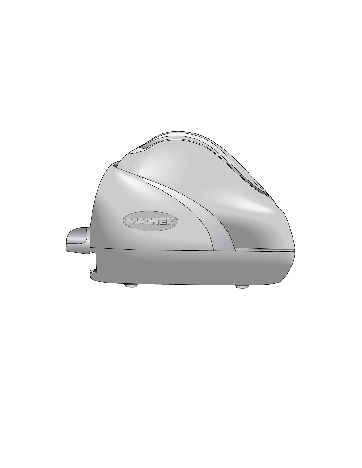
viii
Figure 1-1. MICRImage Check Reader
Page 9

SECTION 1. COMMANDS OVERVIEW
This manual describes the use of all the commands and programmable options available for the
MICRImage Reader. The MICRImage commands can be classified into two general groups:
Configuration Commands and Operational Commands.
CONFIGURATION COMMANDS
As the name implies, these commands are used to configure the MICRImage Reader. These
commands can also be accessed using Insta-change checks and the MICRbase Setup Program for
Windows (see below). Additionally, all the parameters and options controlled by the
configuration commands can be factory set as specified by the user when ordering.
The current list of configuration commands follows for the standard unit (see Section 2 for a
complete description of these commands):
• SWA – Switch A command
• SWB – Switch B command
• SWC – Switch C command
• SWD – Switch D command
• SWE – Switch E command
• SWF – Switch F command
• HW – Hardware command
The current list of configuration commands follows for the Ethernet and Modem Options (see
Section 5 for a complete description of these commands):
• PR0 – MICR IP Address Fixed Value
• PR1 – MICR IP Address Source
• PR2 – MICR IP Subnet Mask Fixed
Value
• PR3 – MICR Subnet Mask Source
• PR4 – Gateway IP Address Fixed Value
• PR5 – Gateway IP Address Source
• PR6 – FTP IP Address Fixed Value
• PR7 – FTP IP Address Source
• PR8 – FTP User ID Fixed Value
OPERATIONAL COMMANDS
Operational commands provide access to additional parameters and options that control the
operation of the MICRImage reader.
The current list of general operational commands follows (see Section 3 for a complete
description of these commands):
• VR – Version command
• RS – Reset command
• LE – LED command
• DM – Disable MICR command
• FC – Format Change command
• SA – Save Configuration command
• PR12 – Filename Configuration
• PR20 – PR29 - Snippets
• PR30 – PR33 - Doc Size Limits
• PR34 – PR35 – MICR Line Technical
Options
• PR9 – FTP User ID Source
• PR10 – FTP Password Fixed Value
• PR11 – FTP Password Source
• PR13 – DNS1 IP Address
• PR14 – DNS2 IP Address
• PR15 – DMS IP Address Source
• PR16 – Phone #
• PR17 – User ID
• PR18 – User Password
• PR19 – FTP File Directory
• EM – Enable MICR command
• BLK – Block Command
• UNBLK – Unblock Command
1
Page 10

MICRImage Check Reader
The following are operational commands that are image specific (see Section 4 for a complete
description of these commands):
• TG – TIFF tag command
• TI – Transmit Image command
• FM – File Memory command
• SI – Store Image command
• SF – Send next image File command
• TC – Set file and timer counter
command
• IS – Image Status command
• AI – Append Image command
• BC – Bar Code command
COMMAND LINE SYNTAX
Unless otherwise noted, commands are “free form” in that spaces may be inserted between
parameters, numbers, and file names (but not between digits). These spaces are ignored. Spaces
within a string are retained.
Lower case letters are converted to upper case letters except in strings. Strings must end with ‘]’
or <CR>. If ‘\’ is used in a string, the character that follows it replaces the ‘\’. For example, if
the command line has the string: Hello[World\] and \\us\\], the resulting string will be:
Hello [World] and \us\.
All commands must end with <CR>.
INSTA-CHANGE CHECKS
The Insta-Change check is a MICR encoded document that contains commands and options used
to set configuration parameters in the MICRImage Reader. Multiple commands and options may
be contained on one Insta-Change check. Also, multiple Insta-Change checks may be required to
configure some of the parameters.
When used, the Insta-Change checks are run through the MICR Reader the same as a standard
check, and the options to be used are automatically configured. When the Insta-Change check is
run through the MICR Reader and read successfully, the LED indicator will blink green. If the
LED indicator turns red, the read is not successful. Try again or use a different Insta-Change
check. To obtain Insta-Change checks, notify a MagTek representative and specify what option
will be used.
MICRBASE SETUP PROGRAM FOR WINDOWS
The MICRbase setup program (P/N 22000021) allows the user to control all the programmable
options available in the MICRImage Reader.
2
Page 11

Section 1. Commands Overview
The program provides a graphical, user-friendly interface that hides the complexities involved in
manually entering MICRImage commands. The user is no longer required to know the specific
commands or the detail data associated with each command. However, the program still allows
manual entry of commands for advanced users. For more detailed information, refer to the
MICRbase Setup Program Reference Manual (P/N 99875102).
The MICRbase setup program may also be downloaded from the Internet at www.magtek.com
under Software/Demo Programs.
3
Page 12

MICRImage Check Reader
4
Page 13

SECTION 2. CONFIGURATION COMMANDS
Configuration commands are used to setup configuration parameters in the MICRImage Reader.
A complete description of these commands follows:
SWITCH COMMANDS
These commands control internal “software” switches used to configure the MICRImage reader.
The switch commands include SWA, SWB, SWC, SWD, SWE, SWF, SWI, HW, FC, PR12, and
SA commands.
When sending configuration data for a software switch, 8 ASCII bits must always be provided
(“0”= hex 30, and “1”=hex 31). The MICRImage will execute the command but it will not reply.
For example, to execute the SWA command with configuration data, send the command as
follows:
SWA 01010101<CR>
To make a switch command permanent, follow the switch command with the SA command
(Save command) as follows:
SWA 01010101<CR>
SA <CR>
If a switch command is sent without configuration data, MICRImage will reply with the current
settings for that switch.
SWA COMMAND – HOST PORT PARAMETERS
This command controls the communication parameters for the RS-232 Host port. The
parameters for this command are listed in Table 2-1.
Note
The MICRImage includes an RS-232 auxiliary port that can be
configured in a similar manner using the SWD command.
5
Page 14

MICRImage Check Reader
Table 2-1. SWA Command – Host Port Parameters
BITS FUNCTION
7 6 5 4 3 2 1 0
0 0 0 Baud Rate: 57600
0 0 1 Baud Rate: 38400
0 1 0 Baud Rate: 115200
0 1 1 Baud Rate: 1200
1 0 0 Baud Rate 2400
1 0 1 Baud Rate: 4800
1 1 0 Baud Rate: 9600
1 1 1 Baud Rate: 19200
0 0 0 Data, Stop Bits, Parity: 8, 1, None
1 0 0 Data, Stop Bits, Parity: 8, 2, None
0 0 1 Data, Stop Bits, Parity: 8, 1, Even
1 0 1 Data, Stop Bits, Parity: 8, 1, Odd
0 1 0 Data, Stop Bits, Parity: 7, 1, Even
1 1 0 Data, Stop Bits, Parity: 7, 2, Even
0 1 1 Data, Stop Bits, Parity: 7, 1, Odd
1 1 1 Data, Stop Bits, Parity: 7, 2, Odd
0 CTS/DSR: Use
1 CTS/DSR: Ignore
0 Intercharacter Delay: No
1 Intercharacter Delay: Yes
Note
The new settings for the serial port will not become effective unless
SWA has been saved and until the RS command is executed.
Baud Rate
The Baud Rate is one of eight speeds at which the MICRImage communicates with the host.
The lowest speed is 1200 baud, and the highest is 115200.
Data, Stop Bits, and Parity
Data refers to the number of data bits used to transmit every character; the options available are 7
or 8. Stop Bits refer to the number of bits used to indicate the end of transmission for every
character; the options available are 1 or 2. Parity refers to a means of detecting bit-level
transmission errors for every character; the options available are None, Even or Odd.
CTS/DSR
When CTS/DSR (Clear to Send/Data Set Ready) is set to Ignore, the MICRImage sends data to
the host without waiting for the CTS and DSR signals to be active. When CTS/DTS is set to
Use, the MICRImage waits for the CTS and DSR signals to be active before sending data.
6
Page 15

Section 2. Configuration Commands
Inter-character Delay
The inter-character delay is used to increase the time between characters transmitted from the
MICRImage. The delay between characters is 13 ms for baud rates of less than 9600 and
approximately 1ms for baud rates of 9600 and higher.
SWB COMMAND – MESSAGE FORMAT PARAMETERS
The SWB command controls the message format, shown in Table 2-2.
Table 2-2. SWB Command – Message Format
BIT FUNCTION
7 6 5 4 3 2 1 0
0 0 <LF>: No
0 1 <LF>: Yes
0 0 <CR>: No
0 1 <CR>: Yes
0 0 <ETX>: No
0 1 <ETX>: Yes
0 0 <ESC>: No
0 1 <ESC>: Yes
0 0 <STX>: No
0 1 <STX>: Yes
0 Send Data After Error?: No
1 Send Data After Error?: Yes
0 Send Status After Data?: No
1 Send Status After Data?: Yes
0 0 0 0 0 0 Comm Mode: 0 - Data Only
1 0 0 0 0 0 Comm Mode: 1 - Data <CR>
0 0 0 0 0 1 Comm Mode: 2 - Data -<LF>
0 0 0 0 1 1 Comm Mode: 3 - Data -<CR><LF>
0 0 1 0 0 0 Comm Mode: 4 - <ESC> Data
0 0 1 0 1 0 Comm Mode: 5 - <ESC> Data<CR>
0 1 0 1 0 0 Comm Mode: 6 - <STX> Data<ETX>
1 0 0 0 0 1 Comm Mode: 7 - Packet Mode
(<STX>Data<ETX><LRC>)
Control Characters and MICR Data
Control Characters may be added to the MICR data message. The characters are always in the
following locations:
<STX> <ESC> data <ETX> <CR> <LF>
The control characters, descriptions, and hex values are shown in Table 2-3.
7
Page 16

MICRImage Check Reader
Table 2-3. Control Characters
CONTROL
CHARACTER
<STX> Start of Text 02
<ESC> Escape 1B
<ETX> End of Text 03
<CR> Carriage Return 0D
<LF> Line Feed 0A
DESCRIPTION
HEX VALUE
For example, if <STX> and <CR> are set to YES, the message from the MICRImage will look
like this:
<STX>data<CR>
Communication Modes
The selection of Comm Modes is a quick way of selecting multiple Control Characters. For
instance, to send a carriage return/line feed pair after the data, you can specify Comm Mode 3.
Comm Mode 7, also known as Packet Mode, calculates an LRC (Longitudinal Redundancy
Check), and appends it to the data message. Also, if a <NAK> (hex 15) character is received in
this mode, the MICRImage will resend the last message.
Send Data After Error
The parameter Send Data After Error specifies whether the MICRImage will return data to the
host after a read error. If YES is selected and the MICRImage reads a check with an error, the
MICRImage will send the data back to the host. If NO is selected and the MICRImage finds an
error, it will discard the data and nothing will be sent. The error conditions are listed in
Table 2-4.
Table 2-4. Error and Status Codes
PRIORITY CODE TYPE DESCRIPTION
10 01 Error No MICR data: no transit and no account found
9 09 Status Mexican check
8 08 Status Canadian check
7 05 Error No transit, bad character, bad length, bad check digit
6 07 Error No account, bad character
5 04 Error Bad character in check number
5 04 Status No check number
4 12 Status Short Account (maybe caused by mis-parsed check#)
3 03 Status Low MICR signal, good read
2 10 Status Business check
1 11 Status Amount field present
0 00 Status No error, check OK
8
Page 17

Section 2. Configuration Commands
Notes:
• The LED indicator will turn red on all error conditions.
• The absence of a check number is not considered an error.
• If a multiple error occurs, the error or status code with the highest priority is reported.
• All unreadable MICR characters are transmitted as an “?” ASCII character (hex 3F), except
for Format 00xx (See Section 5).
Send Status After Data Parameter
The Send Status After Data Parameter makes the MICRImage append a two-digit error/status
code to the end of the MICR data. For most formats (See Appendix A) the error/status code will
always be preceded by a forward slash (/). The error/status codes are listed in Table 2-4.
For example, if a Canadian check (code 08) is read and had no errors, and the MICR data is
“1234567890”, then the message from the MICRImage will look like this:
1234567890/08
The status code is always at the end of the data, not the end of the message. For example, using
the above conditions, with the message format set to send <STX> and <ETX>, the message from
the MICRImage will look like this:
<STX>1234567890/08<ETX>
9
Page 18

MICRImage Check Reader
SWC COMMAND – MISCELLANEOUS FUNCTION PARAMETERS
The SWC command controls miscellaneous parameters, shown in Table 2-5 and described
below.
Table 2-5. SWC Command – Miscellaneous Parameters
BITS FUNCTION
7 6 5 4 3 2 1 0
0 CMC-7 Character Set: No
1 CMC-7 Character Set: Yes
0 0 Invalid Commands: ?<CR>
0 1 Invalid Commands : No Reply (Header
Required)*
1 0 Invalid Commands: No Reply (no header
required)
1 1 Ignore all Commands
0 Active RTS: No
1 Active RTS: Yes
0 Data Header: No
1 Data Header: Yes
0 Card Data Message: Multiple
1 Card Data Message: Single
0 Compatible Replies
1 Extended Replies**
0 Send only if MICR (Compatible)
1 ‘No MICR’ Response**
*Header Required means all commands must be preceded by a GS character (Hex 1D).
**Setting these bits means the Reader may not be compatible with applications using previous
MagTek MICR Products.
CMC-7 Character Set
If NO is selected, the MICR Reader will only read E13-B characters. When YES is selected, the
MICR Reader will read both CMC-7 and E13-B characters (see Appendix B). However, the
MICR Reader will only output raw data ("as is" on the check) for checks with CMC-7 characters.
Invalid Command Response
Invalid command response is the action the MICRImage takes upon receipt of a command it
does not recognize. It can also be used to stop the MICRImage from receiving any more
commands.
The first option “?<CR>” is the default. If the MICRImage receives an unrecognized
command, it will return a question mark and carriage return to the host. The MICRImage will
then return to an idle state and wait for further commands or check/credit card reads.
For the second option, “no reply - header required,” the MICRImage will only execute
commands preceded by a GS ASCII character (hex 1D), and it will not reply to invalid
10
Page 19

Section 2. Configuration Commands
commands. When this option is selected, all messages received without a GS header will be
transmitted “as received” through the RS-232 auxiliary port.
For the third option, “no reply,” the MICRImage will execute all valid commands, but it will not
reply to invalid commands.
The fourth option, “ignore all commands,” causes the MICRImage to stop receiving any Host
data and to ignore any further commands. Even the SA (Save) command is ignored and
therefore this fourth option is only temporary. To make this option permanent or to reset it, you
must use an Insta-Change check.
Active RTS
When this function is set to YES, the MICRImage will raise RTS and wait 5 seconds for CTS to
become active before sending any data. If the 5 seconds expire and CTS is not active, the data
message will be discarded and nothing will be sent.
Data Header
If YES is selected, a single character header precedes the data. For MICR data, the message is
transmitted as follows:
‘C’[data]
For card data, the header position on the message is controlled by the Card Data Message
parameter (see below). Therefore, the message may be transmitted as follows:
If Multiple Message: ‘M’[TK1]‘M’[TK2]’M’[TK3]
If Single Message: ‘M’[TK1] [TK2] [TK3]
It is important to note that the Data Header precedes the data and not the message. For example,
if <STX>, <ETX> and Data Header are set to YES, a MICR data message will be transmitted as
follows:
<STX>‘C’[data]<ETX>
Card Data Message
This parameter determines the structure of the output message for the individual tracks when a
credit card is read. If Multiple is selected, the Control Characters (see SWB, below) and Data
Header (see Data Header, above) are added to each track individually. On the other hand, if
Single is selected, all available tracks are lumped together into a single message. For example, if
<STX>, <ETX> and Data Header are set to YES, the output message may be transmitted as
follows:
11
Page 20

MICRImage Check Reader
If Multiple Message: <STX>‘M’[TK1]<ETX><STX>‘M’[TK2]<ETX><STX>‘M’[TK3]<ETX>
If Single Message: <STX>‘M’[TK1] [TK2] [TK3]<ETX>
Extended Replies
There are a number of commands in the standard MICR command set that do not provide any
response when the operation is completed or with a simple '?<CR> when an error occurs. By
setting this option, commands that normally provide no response will return 'OK<CR>' if the
command executes successfully. For commands that respond with a '?<CR>' to report an error,
the extended reply is '?xxx<CR>' where xxx is a three-digit error code. See Appendix D for a
complete listing of the error codes.
‘No MICR’ Response
For applications where both MICR and non-MICR encoded documents will be scanned, setting
this option will provide a 'No MICR' response when no MICR characters are detected.
SWD COMMAND – AUXILIARY PORT PARAMETERS
The SWD command, shown in Table 2-6, controls the communication parameters for the RS-232
Auxiliary Port.
Table 2-6. SWD Command – Auxiliary Port Parameters
BITS FUNCTION
7 6 5 4 3 2 1 0
0 0 0 Baud Rate: 57600
0 0 1 Baud Rate: 38400
0 1 0 Baud Rate: 115200
0 1 1 Baud Rate: 1200
1 0 0 Baud Rate 2400
1 0 1 Baud Rate: 4800
1 1 0 Baud Rate: 9600
1 1 1 Baud Rate: 19200
0 0 0 Data, Stop Bits, Parity: 8, 1, None
1 0 0 Data, Stop Bits, Parity: 8, 2, None
0 0 1 Data, Stop Bits, Parity: 8, 1, Even
1 0 1 Data, Stop Bits, Parity: 8, 1, Odd
0 1 0 Data, Stop Bits, Parity: 7, 1, Even
1 1 0 Data, Stop Bits, Parity: 7, 2, Even
0 1 1 Data, Stop Bits, Parity: 7, 1, Odd
1 1 1 Data, Stop Bits, Parity: 7, 2, Odd
0 CTS/DSR: Use
1 CTS/DSR: Ignore
0 Intercharacter Delay: No
1 Intercharacter Delay: Yes
12
Page 21

Section 2. Configuration Commands
Note
The new settings for the Auxiliary port will not become effective
until the RS command is executed.
Baud Rate
The baud rate is one of eight speeds at which the MICRImage communicates with the host. The
lowest speed is 1200 baud, and the highest is 115200.
Data, Stop Bits, and Parity
Data refers to the number of data bits used to transmit every character; the options available are 7
or 8. Stop Bits refer to the number of bits used to indicate the end of transmission for every
character; the options available are 1 or 2. Parity refers to a means of detecting bit-level
transmission errors for every character; the options available are None, Even or Odd.
CTS/DSR
When CTS/DSR (Clear to Send/Data Set Ready) is set to Ignore, the MICRImage sends data at
the Auxiliary Port without waiting for the CTS and DSR signals to be active. When CTS/DTS is
set to Use, the MICRImage waits for the CTS and DSR signals to be active before sending data.
Inter-character Delay
The inter-character delay is used to increase the time between characters transmitted from the
MICRImage. The delay between characters is 13 ms for baud rates of less than 9600 and
approximately 1ms for baud rates of 9600 and higher.
13
Page 22

MICRImage Check Reader
SWE COMMAND – DATA TRANSFER PARAMETERS
The SWE Command controls parameters related to the transfer of image files. Image Transfer
Options are as shown in Table 2-7.
Table 2-7. SWE Command – Data Transfer Options
BITS FUNCTION
7 6 5 4 3 2 1 0
MICR/MSR Output Port
0 0 Send via RS232 Host Port
0 1 Send via Auxiliary Port
1 0 Send via Network port (Telnet)
1 1 Reserved
0 0 Send via RS-232 host port
0 1 Send via RS-232 auxiliary port
1 0 Send via Network Port (FTP)
0 0 0 Use length + binary
0 0 1 Use XMODEM (128-byte Blocks)
0 1 0 Use XMODEM-1K (1K-byte Blocks)
0 1 1 YMODEM/YMODEM-G
1 0 0 RAW BINARY
Image Output Port
File Transfer Protocol (RS232 ONLY)
MICR/MSR Output Port
This parameter determines which port is used to send MICR and MSR data. If the Network Port
option is chosen, but no Telnet connection has been established, data will be sent out the Host
Port.
Image Output Port
This parameter determines which port is used to transfer image files. The options are the RS232
host port, the RS-232 Auxiliary port, or the Network port.
File Transfer Protocol
This parameter determines which file protocol is used to transfer image files via the RS232 Ports.
The Network port always uses the FTP protocol. A description of the available RS232 Transfer
options follows:
LENGTH + BINARY
In this protocol, the image file is transmitted as binary data. The length precedes the binary data
in the form of a word count (1 word = 2 bytes). If the first byte received is null, the count is
included in the next 3 bytes. If the first byte received is not null, the first and second bytes are the
count. The byte order of the length is always MSB…LSB.
14
Page 23

Section 2. Configuration Commands
XMODEM
In this protocol, the image file is transmitted in blocks of 128 bytes. The protocol includes error
detection information (CRC or checksum). All blocks must be acknowledged by the host, and if
an error is detected, the host will request the block again.
XMODEM-1K
In this protocol, the image file is transmitted in blocks of 1K bytes. The protocol includes error
detection information (CRC or checksum). All blocks must be acknowledged by the host, and if
an error is detected, the host will request the block again.
YMODEM/YMODEM-G
This is a double mode protocol and is used to send multiple files in batch mode. The host
instructs MICRImage whether to use YMODEM or YMODEM-G. In the YMODEM protocol,
the image file is sent in blocks of 1K bytes, and all blocks must be acknowledged by the host. In
the YMODEM-G protocol, the image files are also sent in blocks of 1K bytes, but the blocks are
not acknowledged by the host.
BINARY
In this protocol, the image file is transmitted as binary data but no length is provid ed. The IS
(Image Size) command can be used to query for the size of the image file.
SWF COMMAND – MICR OPTIONS
This command controls miscellaneous options shown in Table 2-8.
Table 2-8. SWF Command – MICR Options
Bits Parameters
7 6 5 4 3 2 1 0
0 Normal Status
1 Enable Extended Status
0 Use MICR
1 Suppress MICR
0 No Transfer Progress Messages
1 Transfer Progress Messages
0 0 Enhanced Reading (ER) disabled
0 1 ER enabled: compare first 2 reads
1 0 ER enabled: compare any 2 reads
1 1 ER enabled: compare all 3 reads
0 0 0 Reserved
Extended Status
The Extended Status Parameter works in conjunction with the Send Status After Data Parameter
(See page 7). Both must be enabled for extended status to be active.
15
Page 24

MICRImage Check Reader
Example Output:
T123456780A1234567C0345/0000
The Extended Status consists of four digits as follows:
1st Digit
0 – OK MICR
1 – Low MICR
2 – No MICR
nd
2
Digit
0 – Standard Check
1 – Business Check
2 – Mexican Check
3 – Canadian Check
3rd Digit
0 – No Status
1 – Amount Present
2 – Short Account
3 – Short Account + Amount Present
4 – No Check#
5 – No Check# + Amount Present
6 – No Check# + Short Account
7 – No Check# + Short Account + Amount Present
4th Digit
0 – No Errors
1 – Chk#
2 – Account
3 – Account + Chk#
4- Transit
5 – Transit + Chk#
6 – Transit + Account
7 - Transit + Account + Chk#
Suppress MICR
If the Suppress MICR function is selected, the MICR line will not be transmitted or placed in tag
270. This function is used with documents that don’t have a MICR line. To override this
setting, see the ‘EM’ command.
16
Page 25

Section 2. Configuration Commands
Enhanced Reading (ER)
This option is available only in units manufactured after 9/01/03.
If ER is selected, the document is scanned three times: forward, reverse, and forward. The
MICR lines produced are compared character by character and mismatches replaced by ‘?’. The
resulting MICR line is the one that will be parsed, formatted, and transmitted.
In the first mode, the first forward scan is compared to the reverse scan and the result is
transmitted. In the second mode, the three lines are compared in pairs and the first pair found
that matches perfectly is transmitted. In the third mode, all three MICR lines are compared and
the result transmitted.
Transfer Progress Messages
If the Transfer Progress Messages function is selected, the following messages will be sent to the
host indicating the progress of network communications.
DIAL -Dialing
NETLOG -Logging into network
NETCOM -Connected to network
FTPLOG -Logging into FTP server
FTPCON -Connected to FTP server
DISCON -Disconnected
F=filename -file being transferred
17
Page 26

MICRImage Check Reader
SWI COMMAND – IMAGE PARAMETERS
The SWI Command, shown in Table 2-9, controls the image parameters.
Table 2-9. SWI Command – Image Parameters
BIT FUNCTION
7 6 5 4 3 2 1 0
0 0 200 DPI (Default)
0 1 Reserved
1 0 Reserved
1 1 Reserved
0 Reserved – Set to 0
1 Auto-save image
0 SI command saves image
1 Auto-send image
0 TI command sends image
0 0 0 Compressed Bitonal (B/W) CCITT-G4
1 0 0 Bitonal (B/W) (1 Bit/Pixel)
1 0 1 4 Level Grayscale (2 Bits/Pixel)*
1 1 0 16 Level Grayscale (4 Bits/Pixel)
1 1 1 256 Level Grayscale (8 Bits/Pixel)
*This option is not defined in the Base TIFF Specification and may cause problems for some TIFF
viewers.
Image Type
Image Type
This option selects the number of bits used for each pixel, or in other words, the number of
shades of gray. The bitonal image is compressed using CCITT-G4, a lossless compression (no
loss of image quality), resulting in file sizes approximately 10K. Grayscale images are not
compressed and will be significantly larger (e.g., a personal check using 8-bit Grayscale will
create a file size of approximately 640K).
18
Page 27

Section 2. Configuration Commands
HW COMMAND – HARDWARE PARAMETERS
This command controls miscellaneous hardware options shown in Table 2-10.
Table 2-10. HW Command
7 6 5 4 3 2 1 0 PARAMETERS
0 Y Option: Disable
1 Y Option: Enable
0 Track 3: Disable
1 Track 3: Enable
0 Track 2: Disable
1` Track 2: Enable
0 Track 1: Disable
1 Track 1: Enable
0 ID Card decoding: Disable
1 ID Card decoding: Enable
0 EMF detect: Yes
1 EMF detect: No
0 0 These bits are always set to 0
Disable/Enable Y Option
Enable this parameter when using a Y-cable to connect an additional device on the RS-232 Host
Port. This parameter allows the MICRImage and the additional device to receive/transmit data
from the Host.
One important consideration is to determine how the MICRImage should respond to all data
received from the Host. This response is controlled by the Invalid Command Response
parameter. (See SWC Command, above.)
Disable/Enable Tracks
Each Track can be enabled or disabled individually. The tracks are always transmitted in
ascending order: TK1, TK2, TK3. For example, if TK1 and TK3 are enabled and TK2 is
disabled, the reader will transmit TK1, TK3.
ID Card Decoding
The MSR has two modes of operation. In the first mode, ID Card decoding disabled, the MSR
will only read ISO encoded cards. In the second mode, ID Card decoding enabled, the MSR will
read and auto discriminate ISO, AAMVA, and CDL encoded cards. When a card is swiped, the
LED indicator will turn red and indicate an error if any of the enabled tracks read is incompatible
with the selected mode of operation. TK2 is a standard track for all types of cards.
19
Page 28

MICRImage Check Reader
EMF Detect
The EMF Detect option allows the MICR Reader, when idle, to monitor EMF interference in its
immediate environment. If YES is selected, the LED indicator will blink red/green when the
MICR Reader detects a signal with amplitude large enough to affect check reading. If NO is
selected, the MICR Reader will not monitor nor indicate the presence of EMF interference.
FC – FORMAT CHANGE COMMAND
Formats are used by the MICRImage to process and transmit the MICR fields. The Format
command allows the selection of a format from the Format List, Appendix A. The data for this
command consists of 4 digits (ASCII characters 0-9). To execute, send the command as follows:
FC 6600<CR> (with data)
or
FC <CR> (without data)
When sending data, all 4 digits must be provided. The MICRImage will execute the command
but it will not reply. The new settings become effective immediately. To make this command
permanent, use the SA command described below.
If no data is provided, the MICRImage will respond with the current setting.
FILE NAMES
Each image that is transmitted or saved is given a unique file name. A file specification
describes the content of a file name and may be given on the command line by using the ‘N’
parameter of the TI or SI command. See Section 4. If the ‘N’ parameter is not used in these
commands, the file specification is taken from property 12. (See the PR12 command in Section 6
for the characters that may be used in a file specification.) If property 12 is empty, a default file
name is used. If the file name specified already exists in internal storage, an extension is added
to the file name to make it unique. For example, if the name to be created is IMAGE.TIF and it
already exists, the name IMAGE_0.TIF will be created and used for the current image.
DOCUMENT SIZE LIMITS
Used to set minimum and maximum size limits for scanned documents. An improper scan can
result in a short or skewed image. It is usually not desirable to transmit or save such an image.
If size limits are set and the image falls outside those limits, the auto-send, auto-save, and append
image operations will not be performed and an error will be returned. See PR30 – PR33 in
Section 6.
MICR LINE TECHNICAL OPTIONS
Used to set MICR line signal characteristics to optimize low MICR detection. See PR34 – PR35
in Section 6.
20
Page 29

Section 2. Configuration Commands
SA – SAVE COMMAND
All changes are considered temporary until the Save command is executed. The Save command
saves all changes to the MICRImage memory and makes them permanent. The MICRImage will
execute the command but it will not reply. To execute, send the SA command followed by a
carriage return as follows:
SA<CR>
21
Page 30

MICRImage Check Reader
22
Page 31

SECTION 3. GENERAL OPERATIONAL COMMANDS
This section describes the Version command, Reset command, LED commands, Disable and Enable
Module commands, and Block and Unblock commands.
VR – VERSION COMMAND
The Version command gives the current firmware revision in the MICRImage. To execute, send the VR
command followed by a carriage return as follows:
VR<CR>
The MICRImage responds as follows:
Version [firmware revision]<CR>
SE – SERIAL NUMBER COMMAND
The Serial Number Command responds with the MICRImage unit serial number. To execute, send the
SE command followed by a Carriage Return as follows:
SE<CR>
The MICRImage responds:
SE = [serial#]<CR>
RS – RESET COMMAND
The Reset command resets the MICR program, and it resets the serial port to the saved settings provided
by SWA. To execute, send the RS command followed by a carriage return as follows:
RS<CR>
LE – LED COMMAND
The LE command is used to control the LED’s color pattern, and the duration of the pattern.
The color pattern has four segments. Each color segment can be green, red, or amber (the amber is
produced by turning red and green on). The definition of the color pattern is better described using a byte,
where two bits control an individual segment, and each bit controls a color (on or off):
Segment 1 Segment 2 Segment 3 Segment 4
Red Green Red Green Red Green Red Green
0/1 0/1 0/1 0/1 0/1 0/1 0/1 0/1
23
Page 32

MICRImage Check Reader
For example, to setup a color pattern where the LED illuminates green-re d-green-red, the byte value
would be “01100110” (decimal 102). The decimal value of this byte is used with the LE command. In this
example, the LE command is executed as follows:
LE 102<CR>
Table 3-1 lists common color patterns with their values and descrip tions:
Table 3-1. LED Control
Color Pattern Color Value
(Decimal)
Off/Off/Off/Off 0 LED Off
Green/Green/Green/Green 85 Steady Green
Red/Red/Red/Red/ 170 Steady Red
Amber/Amber/Amber/Amber 255 Steady Amber
Green/Green/Off/Off 80 Blink Green Slow
Red/Red/Off/Off 160 Blink Red Slow
Amber/Amber/Off/Off 240 Blink Amber Slow
Red/Red/Green/Green 165 Blink Red/Green Slow
Green/Off/Green/Off 68 Blink Green Fast
Red/Off/Red/Off 136 Blink Red Fast
Amber/Off/Amber/Off 204 Blink Amber Fast
Red/Green/Red/Green 153 Blink Red/Green Fast
Red/Green/Off/Off 144 Fast Red/Green Off
Green/Green/Green/Red 86 Green + Fast Red
Red/Red/Red/Green 169 Red + Fast Green
Description
Once the color pattern is defined, the pattern is repeated for a default interval of 3 seconds. A different
time period can be specified using the LE command and providing a new value in seconds, up to 65. For
example, to setup a 5 second interval for the color pattern above, the LE command is executed as follows:
LE 85,5<CR>
Note
The total time for each color pattern is 0.4 seconds (i.e. each segment lasts 0.1 seconds).
DM – DISABLE MICRIMAGE COMMAND
This command disables the document reading function and turns off the LED. Communications are not
affected, and Insta-change checks may still be scanned, but the MICR line will not be sent.
DM<CR> Insta-change checks only may be scanned
DMX<CR> No scans at all
24
Page 33

Section 3. General Operational Commands
EM – ENABLE MICRIMAGE COMMAND
This command enables the document reading function, and the LED will turn green. To execute, send the
EM command followed by a carriage return as follows:
EM<CR>
One of the following optional parameters may be used:
N Suppresses MICR for next scan regardless of SWF. Afterwards, revert to
SWF.
M Detect MICR for next scan regardless of SWF. Afterwards, revert to SWF.
Example: EMN<CR>
BLK – BLOCK COMMAND
The BLK Command allows an application on any port to temporarily block command processing on all
other ports for a set period of time, by default 10 seconds, or until the UNBLK command is sent.
Optionally the duration (in seconds) can be specified as ‘BLK n’ where n can range from 0 to 65. Setting
the duration to 0 will allow blocking with no timeouts.
BLK<CR> 10-second timeout
BLK 15<CR> 15-second timeout
UNBLK – UNBLOCK COMMAND
The UNBLK command allows the MICRImage to continue processing input from all available ports.
UNBLK<CR>
25
Page 34

MICRImage Check Reader
26
Page 35

SECTION 4. IMAGE SPECIFIC COMMANDS
This section describes the commands available for the transmission, storage and management of images.
Some important characteristics of the images generated by MICRImage are:
• The default image resolution used is 200 dpi.
• Images are compressed according to ITU T.6, also referred to as CCITT Group 4.
• The images are stored using the TIFF file format.
• The TIFF format contains a number of descriptive fields of data (“tags”) each tagged with a number
(up to 65534). Many of these tags are predefined and contain items such as image length, height, and
compression method.
• The TIFF format also allows the inclusion of an unlimited amount of private or special-purpose
information utilizing a number of user defined tags. MICRImage provides commands that allow
programming of these TIFF tags.
The following TIFF tags are included in every image file. Tag # 270 can be modified using MICRImage
commands.
Tag # Tag Name Content
270 IMAGE DESCRIPTION Contains formatted MICR line unless changed by the
user.
271 MAKE “MagTek, Inc.”
272 MODEL “MICRImage RS232 [unit’s serial number]”
305 SOFTWARE [firmware version]
The following TIFF tags are available and can be programmed using the MICRImage commands:
Tag # Tag Name Content
269 DOCUMENT NAME User specified.
285 PAGE NAME User specified.
306 DATE/TIME User specified.
315 ARTIST User specified.
316 HOST COMP UTER User specified.
333 INK NAMES User specified.
337 TARGET PRI NTER User specified.
33432 COPYRIGHT User specified.
32768
to
65534
Undefined
User specified.
27
Page 36

MICRImage Check Reader
TG – TIFF TAGS COMMAND
This command stores the specified data in the tag section of the TIFF file for the last image scanned. The
following optional parameter may be used repeatedly:
Tn=string] Set tag n to “string”.
Example: TG T315=Fred] T337=Laserjet<CR>
An existing tag can be deleted by setting it to a null string as follows:
TG T315=]<CR> will delete Tag 315. All user tags are deleted when a new document is scanned or an
image is saved.
If this command is used without parameters, the current tags are listed.
Example: TG<CR> may return:
271 MagTek, Inc.
272 MICRImage RS232 (12345678)
305 Version MI_00.00.00
Note
If the image is “locked” (see TI command), the TG command with
parameters is ignored and will return an error.
The TIFF format allows multiple strings under the same Tag #. The strings are separated by ‘^’ as
follows:
TG T337=TED^FRED^JOE]<CR>
These separators are converted to ASCII NUL in the Tag.
TI – TRANSMIT IMAGE COMMAND
This command instructs the MICRImage to transmit the current image just captured using the image
transfer options selected in SWE. To execute, send: TI<CR>.
The following optional parameters may occur in any order:
C0 Transmit image through the host RS232 port
C1 Transmit image through the auxiliary RS232 port
28
Page 37

Section 4. Image Specific Commands
C2 Transmit image through the network port using FTP
F0 Use the LENGTH + BINARY protocol *
F1 Use the XMODEM protocol*
F2 Use the XMODEM-1K protocol*
F3 Use the YMODEM/YMODEM-G protocol*
F4 Use the BINARY protocol*
*RS232 only
Nfilename specification] Specify the file name using the same special characters and
rules described in PR12 – File Name Specification (See Section 6). If this
parameter is not used, the file name given by PR12 will be used or a default file
name if PR12 is empty.
Tn=string] Set tag n to “string”.
(snippet) Send the specified portion of the image (See SNIPPETS page 34).
Sn where n is 0-9 specifying PR20-PR29 which contain snippets or
any of the above parameters. See Predefined Snippets in Section 6.
Example: TI C1 F2 (T100L300) T315=Fred] T337=Laserjet] N MyImage.tif<CR>
Note
Once the current image has been transmitted, the image becomes “locked”
and cannot be appended with additional images using the AI command and
only the Cn and Fn parameters will be accepted. Others will be ignored.
FM – FILE MEMORY COMMAND
When images are being stored in the internal storage memory, the MICRImage keeps a record on the
following:
• Each image stored is assigned an ascending count number.
• MICRImage keeps a pointer on the next image to be retrieved
• The images are retrieved first in, first out.
• MICRImage also keeps tabs on the number of stored images, and the amount of memory remaining.
The FM command is used to obtain the current file memory status. To execute, send the FM command as
follows:
FM<CR>
29
Page 38

MICRImage Check Reader
The MICR image will reply with the current file memory status as follows:
a,b,c <CR>
Where ‘a’ is the number of the next image to be retrieved, ‘b’ is the number of stored images, and ‘c’ is
the number of bytes remaining. Status ‘a’ will be zero (0) whenever the internal storage memory is empty
or after the last image has been sent out.
The FM command accepts any one of the following optional parameters:
ERASE All files are erased from internal storage. This may take up to 45 seconds.
The response is the memory status as described above.
Example: FM ERASE<CR> will return 0,0,1048576<CR>.
DELETE name, … Deletes the named files from internal storage and returns the file status as
described above if successful. This does not make the storage available for
new files, however. When the last file is deleted, the storage is erased. If a
named file is not found, the command is aborted and an error is returned.
The names may be separated by spaces or by a comma.
Example: FM DELETE img23.tif, myimage.tif<CR> may return 1,3,234567<CR>.
R Resets the file pointer to “1” (first file). The response is the
memory status as described above.
Example: FM R<CR> may return 1,5,987654<CR>.
LIST Sends the file names and their sizes in bytes as follows:
Name, size<CR>.
Example:
FM LIST<CR> may return
IMAGE1.TIF,5678<CR>
IMAGE2.TIF,6543<CR>
30
Page 39

Section 4. Image Specific Commands
SI – STORE IMAGE COMMAND
This command instructs MICRImage to store the current image just captured into internal storage
memory. The stored image is assigned an ascending count number. Also, when this operation is
completed, MICRImage always replies with an updated file memory status.
To execute, send the SI command as follows:
SI<CR>
The MICR image will reply with the current file memory status as follows:
a,b,c <CR>
Where ‘a’ is the number of the next image to be retrieved, ‘b’ is the number of stored images, and ‘c’ is
the number of bytes remaining. Status ‘a’ will be zero (0) whenever the internal storage memory is empty
or after the last image has been sent out.
Note
If there is no current image available to store (no check has been read), or
if the internal memory is full, the MICRImage will return an error.
The SI command also allows the same parameters used with the TI command except Cn and Fn, and their
functionality is exactly the same (for details see the TI command above). Some examples using the SI
command with these parameters follow:
SI NIMAGE1.TIF<CR>
SI T306=10/22/99] NIMAGE.TIF] SO<CR> to save the current image as file
“IMAGE.TIF” with Tag 306 as given and consisting of the snippet(s) given by PR20.
Note
Once the current image is stored into the internal storage area, the current
image memory is cleared. To access the image, use the SF command.
SF – SEND NEXT IMAGE FILE COMMAND
The SF command is used to send the next image file (from internal storage memory) using the image
transfer options selected in SWE.
To execute, send the SF command as follows:
SF<CR>
31
Page 40

MICRImage Check Reader
The following optional parameters may be used in any order:
Cn Comm port as described in the TI command.
Fn Transfer protocol as described in the TI command.
A Send all remaining files. If the transfer protocol is
XMODEM or XMODEM-1K, only the next file is sent.
N name, …] Sends the named files. The names may be separated by a
comma or spaces. If a named file is not found, the command is aborted and
an error is returned. If the transfer protocol is XMODEM OR XMODEM1K, only the first named file is sent
Example: SF C0 F3 N myimage.tif yurimage.tif<CR>
TC – SET FILE TIMER/FILE COUNTER COMMAND
This command is used to set two internal counters in the MICRImage whose values may be inserted into
file names using the TI and SI commands. They both set to zero at power-on. The following optional
parameters may be used in any order:
Tn Sets the file timer to n seconds. This value is incremented each second. The
maximum value is 4,294,967,295 which rolls over to zero.
Cn Sets the file counter to n. The maximum value is 65,535 which rolls over to zero.
The current value is used when a new file name is created and is then incremented.
Example: TC T1000 C50<CR>
If this command is used without parameters, the current values are returned.
Example: TC<CR> may return
TC=T1003,C50<CR>
IS – IMAGE STATUS COMMAND
This command instructs the MICRImage to transmit the status of the current image in local memory. To
execute, send the command as follows:
IS<CR>
32
Page 41

Section 4. Image Specific Commands
The MICRImage responds with a status string formatted as follows:
abc,size,fn<CR>
where
a = image status (N-None, S-Scanned, L-Scanned/Locked)
b = compression(N-None, G-compressed)
c = image type (0-None, 1,2,4,8 bit)
size = image size in # of bytes
fn = image filename (noname- name not determined yet)
Example responses:
NN0,0,noname<CR> - No image in memory
SG1,5333,noname<CR> - Scanned B/W image (5333 bytes) in memory
LG1,5333,file7.tif<CR> - Same image after being sent (image is now locked)
One of the following optional parameters may be used:
F Returns the status information as described above for the next file to be transmitted by the
SF command.
D Returns the length and height in pixels of the current image.
K Kills (cancels) the current image. This is done automatically whenever an image is saved
in internal storage or a new document is scanned.
Examples: IS F<CR> may return
LG1,9726,MYIMAGE.TIF<CR>
IS D<CR> may return
1208,540<CR>
IS K<CR> returns NN0,0,noname<CR>
AI – APPEND IMAGE COMMAND
The AI command can be used to append additional documents to the same bi-tonal compressed file. The
user is not prompted for the next scan. This command may be canceled by typing cntl-X. The following
optional parameters may be used:
33
Page 42

MICRImage Check Reader
R Rescan. This will cancel the previous scan unless it has been followed by an IS or
TI command.
K Kill the current file.
The formatted MICR line is placed in tag 270 whether it has errors or not.
Any number of scans can be appended limited only by the size of the file buffer. If the file buffer
overflows, an error is returned and the entire file is canceled.
Examples: AI<CR> To append the next document scanned.
AIR<CR> To cancel the previous scan.
AIK<CR> To kill the current file.
Note
Tags added after this command as well as existing tags will be associated
with the appended image.
SNIPPETS
A snippet is a rectangular area within an image. To specify a snippet, enclose it in parentheses as follows:
( Tn Bn Ln Rn ) where T, B, L, and R are the top, bottom, left, and right borders of the area and n
is the distance of the border from an edge of the image. If n is positive, it represents the distance from the
bottom or right edge; if negative, from the top or left edge. An integer represents pixels, a number
containing a decimal point represents inches, and a number with a comma in place of the decimal point
represents centimeters. There are 200 pixels per inch. These four parameters are all optional and may
occur in any order.
Note
When a snippet is specified, the resulting file will be uncompressed
grayscale with 1, 2, 4, or 8 bits per pixel as given in SWI.
Multiple snippets may appear on the same command line. The commands that may use snippets are: TI,
SI, and BC. For example:
TI ( T375 B325 L500 R100)<cr> specifies a snippet 51 pixels high by 401 pixels long.
SI ( L2.0) ( R-1,8)<cr> specifies two snippets: (the right-most 2 inches) and (the left-most
1.8 cm).
34
Page 43

Section 4. Image Specific Commands
If snippets are defined using MICRBase or property commands PR20 – PR29 (see Section 6), they may
be referred to on the command line by number using the ‘Sn’ parameter where n is 0-9. For example:
BC1 S5<cr> specifies the pre-defined snippet #5 (PR25) to be scanned for bar code 39.
Note
These ten pre-defined snippets (PR20-PR29) are limited to two snippets
each or any other valid command parameters, totaling 45 characters or
less.(See Section 6.)
BCn – BAR CODE COMMAND
The bar code command may be used to scan one or more snippets for a specified bar code symbol. Each
snippet is scanned three times: top edge, middle, bottom edge (horizontal) or left edge, middle, right edge
(vertical). The required parameter n must be one of the following:
1 Bar code 39. Send all characters including check character.
2 Bar code 39. Send all characters except check character if valid, else error.
3 Bar code Interleaved 2 of 5. Send all characters including check character.
4 Bar code Interleaved 2 of 5. Send all characters except check character if valid, else error.
5 Bar code 128. Send all characters except check character if valid, else error.
The following optional parameters may occur in any order:
V Scan vertically. The default is horizontal if the snippet is wider than it is high or vertical if
higher than it is wide.
( Snippet. See snippet description. Multiple snippets are allowed. The first valid bar code
symbol encountered terminates the command.
Sn where n=0 – 9. Pre-defined snippet (PR20 – PR29). See snippet description and
Section 6.
Examples:
BC5 S3 (T200 B150 L800 R300)<cr> Use bar code 128, scan predefined snippet(s) given in
PR23, then scan the new snippet.
BC2 V S8<CR> Use bar code 39, force vertical scan of all snippets in
PR28.
35
Page 44

MICRImage Check Reader
36
Page 45

SECTION 5. NETWORK INTERFACE
The Network interface allows for the following:
• Transfer of images to a host using FTP (file transfer protocol)
• Telnet communication between the MICR and a host
• Configuration of Ethernet parameters from DHCP (Dynamic Host Configuration Protocol) or fixed
(nonvolatile) MICR memory
• Log in to network using modem and PPP. Configuration of some parameters using IPCP.
NETWORK IMAGE FTP
Images can be transferred to a host by using FTP. This is accomplished by using the image transfer
commands TI and SF in coordination with the SWE configuration command. See the documentation that
describes these commands for more details.
NETWORK TELNET COMMUNICATIONS
In addition to RS232 communications, a host can communicate with a MICR using Telnet. During the
Telnet session the host acts as the client and the MICR is considered the server. The host is responsible
for establishing the Telnet connection and only one host can connect to the MICR at any one time. Using
Telnet, the host can send commands and receive responses as well as MICR and MSR data depending on
the configuration.
ETHERNET OR MODEM NETWORK CONFIGURATION
The MICR needs a number of parameters to be set up in order to communicate using the Network
interface. Ethernet parameters include the MICR IP Address, MICR IP Mask, Gateway/Router and DNS
IP Address. Modem parameters include Phone number, User ID and Password. Both interfaces use FTP
IP Address, FTP User ID, FTP Password, and FTP File Directory. These parameters are generally loaded
when the MICR powers up or is reset. These parameters can be obtained from nonvolatile memory within
the MICR (fixed), or optionally with the Ethernet interface using DHCP, or a combination of both
methods. Note that in order to obtain any parameter using DHCP, the MICR IP Address must be obtained
by DHCP. It is critical that the MICR is configured properly in order to obtain these parameters correctly.
See the documentation that describes these parameters for more details.
NETWORK CONFIGURATION PROPERTIES
The properties needed to configure the unit for network communications are:
PR0 – PR11 and PR13 – PR19. See Section 6.
37
Page 46

MICRImage Check Reader
NETWORK DEBUG COMMANDS
PING – Send ECHO Packet Command
The PING command allows the user to check on the Ethernet or Modem connection by having the
MICRImage send a number of ECHO packets to the FTP server and measure the time required for a
response back.
PING<CR>
The MICRImage responds:
Pinging FTPSRV with 64 bytes of data
Reply rcvd from [192.11.12.13]: time=3ms.
Reply rcvd from [192.11.12.13]: time=2ms.
Reply rcvd from [192.11.12.13]: time=1ms.
Reply rcvd from [192.11.12.13]: time=2ms.
Packets: Sent 4, Rcvd 4
Optionally you can specify the IP address in the command. For example:
PING 192.12.11.123<CR>
ED – Ethernet Debug Command
Provides information about the Network parameters currently being used by the MICRImage. This is
especially useful when verifying the dynamic configuration using DHCP. Also can provide debug trace
for further troubleshooting. The list of ED commands is as follows:
ED<CR> OUTPUT NETWORK INFO
ED1<CR> ENABLES FTP DEBUG MESSAGES
ED2<CR> ENABLES PPP DEBUG MESSAGES
ED3<CR> ENABLES BOTH FTP AND PPP DEBUG
For example, the MICRImage responds to ED<CR> with:
Link detected.
CHKSCN -> MAC=001A10000002
CHKSCN -> IP addr=192. 37. 11.220, Subnet mask=255.255.255.0
ROUTER -> IP addr=192. 37. 11. 70, Subnet mask=255.255.255.0
FTPSRV -> IP addr=192. 37. 12.205, Subnet mask=255.255.255.0
DHCPSV -> IP addr=192. 37. 11. 20
38
Page 47

Section 5. Network Interface
XU – PPP Dial Up (Modem Only) Command
Connects to network. Stays connected after file transfer. Modem will timeout-disconnect if no activity
detected in 2 minutes.
XD – Modem Disconnect (Modem Only) Command
Hangs up phone connection.
DHCP SERVER CONFIGURATION
To utilize the DHCP configuration for MICRImage with Ethernet, the server must be set up appropriately.
Please refer to the documentation for your particular DHCP device for more details. The server should
already be configured to handle the individual IP address and subnet mask. Check to make sure the
Router/Gateway option #3 is also activated if required.
To dynamically configure the FTP parameters, three user-defined options must also be set up. These are:
179 FTP Username type String, Max Length=16
180 FTP Password type String, Max Length=16
181 FTP SERVER ADDRESS type String, Max Length=100
39
Page 48

MICRImage Check Reader
40
Page 49

SECTION 6. PROPERTY COMMANDS
The following properties are nonvolatile (permanently saved in FLASH memory). The "SA" command
must be used to save these properties whenever they are changed.
The command format to change a property is:
PRn=string<CR> where n is the property num b er and string is the new value. For example,
PR5=1<CR> sets property 5 to 1. An error is returned if the string is not a
valid value for the given property.
If the command is sent without a value, the current setting is returned. For example, PR5<CR> may
return PR5=1<CR>.
PR0 – MICR IP Address Fixed Value (Ethernet Only)
This sets the fixed IP address for the MICR unit. For example:
PR0=192.11.12.127<CR>
PR1 – MICR IP Address Source (Ethernet Only)
PR1=0 - sets unit to configure MICR IP using DHCP
PR1=1 - sets unit to use fixed value (see PR0)
Note
This must be set to DHCP if any other configuration is to be obtained via DHCP.
PR2 – MICR IP Subnet Mask Fixed Value (Ethernet Only)
This sets the fixed IP subnet mask used by the MICR unit. For example:
PR2=255.255.255.0<CR>
PR3 – MICR Subnet Mask Source (Ethernet Only)
PR3=0 - sets unit to configure the subnet mask using DHCP
PR3=1 - sets unit to use fixed value (see PR2)
PR4 – Gateway IP Address Fixed Value (Ethernet Only)
This sets the fixed IP address for the gateway/router. For example:
PR4=192.11.12.127<CR>
41
Page 50

MICRImage Check Reader
PR5 – Gateway IP Address Source (Ethernet Only)
PR5=0 - sets unit to configure the gateway IP using DHCP option 3
PR5=1 - sets unit to use fixed value (see PR4)
PR6 – FTP Name/IP Address Fixed Value
This sets the name or fixed IP address for the FTP server. The maximum allowable length is 100
characters. For example:
PR6=192.11.12.127<CR>
or
PR6=ftp.checks.com<CR>
PR7 – FTP IP Address Source
PR7=0 - sets unit to config the FTP server IP using DHCP option 181 (Ethernet only)
PR7=1 - sets unit to use fixed value (see PR6)
PR8 – FTP User ID Fixed Value
This sets the user ID used for the FTP server. The maximum allowable length is 16 characters. For
example:
PR8=MICRIMAGE<CR>
PR9 – FTP User ID Source
PR9=0 - sets unit to config the FTP User ID using DHCP option 179 (Ethernet only)
PR9=1 - sets unit to use fixed value (see PR8)
PR10 – FTP Password Fixed Value
This sets the fixed password used for the FTP server. The maximum allowable length is 16 characters.
For example:
PR10=CHECKREADER<CR>
PR11 – FTP Password Source
PR11=0 - sets unit to config the FTP password using DHCP option 180 (Ethernet only)
PR11=1 - sets unit to use fixed value (see PR10)
42
Page 51

Section 6. Property Commands
PR12 – File Name Specification
To configure this property, an ASCII string of valid filename characters must be used. Leading spaces are
ignored. The maximum number of characters is 32. Additionally, MICRImage uses the following list of
special character options to insert predefined sequences in the filename:
• ‘*’ = raw MICR line
• ‘?’ = parsed MICR line according to the FC command
• ‘>’ = current file counter
• ‘<’ = current file timer in seconds
• ‘:’ = unit’s serial number
• ‘ ’ (space) = replaced with underline ‘_’
Note
Use the TC command to set the initial values of the file count and time.
For example, if the desired filename must include the word “image”, followed by the file count, and then
followed by the extension “.tif”, send the command as follows:
PR12=image>.tif<CR>
PR13 – DNS 1 IP Address (Ethernet Only)
This sets the IP address for the DNS 1 server:
PR13=100.100.100.100<CR>
PR14 – DNS 2 IP Address (Ethernet Only)
This sets the IP address for the DNS 2 server:
PR14=100.100.100.101<CR>
PR15 – DNS IP Address Source (Ethernet Only)
PR15=0 - sets unit to configure the DNS1 and DNS2 servers using DHCP option.
PR15=1 - sets unit to use fixed values in PR13 and PR14.
43
Page 52

MICRImage Check Reader
PR16 – Phone (Modem PPP Only)
This sets the user phone number to be dialed by the modem (maximum of 30 characters):
PR16= 714-853-1212<CR>
PR17 – User ID (Modem PPP Only)
This sets the user ID (maximum or 40 characters):
PR17= GOBLIN<CR>
PR18 – User Password (Modem PPP Only)
This sets the user password (maximum of 40 characters). The user password is a ‘hidden’ parameter so
only ‘*’ will be output for each character.
PR18=PAHSWURD<CR>
PR18<CR>
PR18=********<CR>
PR19 – FTP File Directory
This sets the FTP file directory(maximum or 32 characters):
PR19=/IMAGES(CR)
PR20 through PR29 – Predefined Snippets
These properties may contain one or two snippets as described in Section 4 under Snippets, as well as any
command parameters that are valid for the TI, SI, and BC commands. (See these commands for details.)
In effect, these properties may be viewed as extensions of those command lines. For example, given the
following preset properties:
PR20 = (T320 B300 L900 R50) (T415 B350 L900 R300)<CR>
PR28 = C1 NIMAGE.TIF] T333 = MY TAG]<CR>
The following commands could be used:
44
Page 53

Section 6. Property Commands
BC5 SO<CR> to decode the two barcode 128 symbols defined in PR20.
TI F3 S8<CR> to send the current image named IMAGE.TIF containing the tag “MY TAG” to the
auxiliary port using the YMODEM protocol.
The limit for each of these properties is 45 characters.
PR30 – Minimum Length
Sets the minimum length for a document in pixels. A value of zero disables this limit. If the scanned
document is shorter than this length, an error is returned.
PR30=1175<cr>
PR31 – Minimum Height
Sets the minimum height for a document in pixels. A value of zero disables this limit. If the scanned
document is less than this height, an error is returned.
PR31=530<cr>
PR32 – Maximum Length
Sets the maximum length for a document in pixels. A value of zero disables this limit. If the scanned
document is longer than this length, an error is returned.
PR32=1250<cr>
PR33 – Maximum Height
Sets the maximum height for a document in pixels. A value of zero disables this limit. If the scanned
document is higher than this height, an error is returned.
PR33=560<cr>
PR34 – MICR Threshold
Sets the MICR line noise threshold. Range 0 – 255. The useful range is approximately 8 – 25. Lower
values will allow lower amplitude characters to be read but also will make reading more susceptible to
errors caused by EMF noise. Default is 15.
PR34=15<cr>
45
Page 54

MICRImage Check Reader
PR35 – MICR Amplitude Scale
Sets the MICR line low-amplitude detection threshold. Range 0 – 255. Default is 128 which equates to
approximately 42% signal amplitude as described in the X9 MICR Standards. Higher numbers raise the
threshold.
PR35=128<cr>
PR36 – Modem Initialization (Modem PPP Only)
Used to initialize the modem.
PR36=S7=50<cr> Set max time to wait for connection
46
Page 55

APPENDIX A. FORMAT LIST
For check reading, the MICRImage provides the flexibility to format the MICR fields and build a specific
output string that will be transmitted to the Host. These output strings are referred to as Formats. The
MICRImage has a built-in list of Formats (described below) from which the user may select one to
become the active Format every time a check is read. The Formats may be selected using the FC
command (Section 2, Configuration Commands) or Insta-Change Checks provided by MagTek.
Each Format is assigned a 4-digit number. The first two digits indicate the Format number, and the last
two digits are specific parameters used for various functions by each Format. For example, in Format
“0415”, the “04” refers to Format number 4 and the 15 refers the maximum number of characters allowed
for the account field.
Note
The formats listed in this section apply only to U.S. and Canadian checks.
The MICR line on checks from other countries will not be broken or parsed
as described in these formats.
A complete description for each Format follows.
Fmt 00xx:
xx - specify what symbol set to use. Choose from the table
Add xx + 32 - Remove all spaces
Examples:
MICR LINE: T122000218T 1234 5678 9U 1321
FC0001 - t122000218t 1234 5678 9o 1321
Raw Data Format - sends the entire MICR line - where:
Add xx + 16 - change multiple spaces to one space
(+16) FC0017 - t122000218t 1234 5678 9o 1321
(+32) FC0033 - t122000218t123456789o1321.
xx Transit On-Us Amount Dash Error
00 T U $ - ?
01 t o a d ?
02 T O A D ?
03 T U $ - *
04 T U $ 0 ?
05 T U $ 0 *
06 t o a 0 ?
07 T U $ none ?
47
Page 56

MICRImage Check Reader
Fmt 01xx:
FC0100 - Parsed text with dashes
FC0101 - Parsed text, replace dashes with “d”
Field Labels - TR-transit, AC-account #, CK-check #, AM-amount, TP-tpc,
EP-epc
Example: - PTTR444455556;AC 999-222-3;CK11045
Fmt 02xx:
FC0200 - Parsed text with dashes
FC0201 - Parsed text, replace dashes with “d”
Error Labels - PE-parsed error, NE-no error, TR-transit error,
CK-chk # error, TC-transit check digit error,
AM-amount error, OU-on us/account# error, TP-tpc error
Examples: - PTTR444455556;AC999-222-3;CK11045/PENE
Fmt 03xx:
• [acct #]: - maximum of xx characters; when xx=00 all characters are sent
- keep spaces and dashes
Fmt 04xx:
• [acct #]: - maximum of xx characters; when xx=00 all characters are sent
- remove spaces and dashes
Fmt 05xx:
• [acct #]: - maximum of xx characters; when xx=00 all characters are sent
- replace spaces and dashes with zeros
Fmt 06xx:
• [acct #]: - always xx characters, zero filled;
when xx=00 all characters are sent
- replace spaces and dashes with zeros
Fmt 07xx:
• [acct #]: - always xx characters, zero filled;
when xx=00 all characters are sent
- remove spaces and dashes
Fmt 08xx:
• [transit]: - all characters in the field
- keep dashes
• [acct #]: - maximum of xx characters; when xx=00 all characters are sent
- remove spaces and dashes
Parsed Text Format
Parsed Text Format with Error Labels
- PTTR111?11111;AC123456/PETR (“?” = unreadable character)
[acct #]
[acct #]
[acct #]
[acct #]
[acct #]
[transit] [acct #]
48
Page 57

Appendix A. Format List
Fmt 09xx: [transit] [acct #]
• [transit]: - all characters in the field
- keep dashes
• [acct #]: - maximum of xx characters; when xx=00 all characters are sent
- replace spaces and dashes with zeros
Fmt 10xx:
• [transit]: - all characters in the field
- keep dashes
• [acct #]: - always xx characters, zero filled;
when xx=00 all characters are sent
- replace spaces and dashes with zeros
Fmt 11xx:
• [transit]: - all characters in the field
- keep dashes
• [acct #]: - maximum of xx characters; when xx=00 all characters are sent
- remove spaces and dashes
• [check #]: - all characters in the field
Fmt 12xx:
• [transit]: - all characters in the field
- keep dashes
• [acct #]: - maximum of xx characters; when xx=00 all characters are sent
- remove spaces and dashes
• [check #]: - always 6 characters, zero filled
Fmt 13xx:
• [transit]: - all characters in the field
- keep dashes
• [acct #]: - maximum of xx characters; when xx=00 all characters are sent
- remove spaces and dashes
• [check #]: - always 6 characters, zero filled
[transit] [acct #]
[transit] 'T' [acct #] 'A' [check #]
[transit] 'T' [acct #] 'A' [check #]
[transit] 'T' [acct #] 'A' [check #] '000'
49
Page 58

MICRImage Check Reader
Fmt 14xx:
• [transit]: - all characters in the field
- keep dashes
• [acct #]: - maximum of xx characters; when xx=00 all characters are sent
- remove spaces and dashes
• [check #]: - always 6 characters, zero filled
Fmt 15xx:
• [bank #]: - all characters in the field
- keep spaces and dashes
• [acct #]: - maximum of xx characters; when xx=00 all characters are sent
- remove spaces and dashes
Fmt 16xx:
• [bank #]: - all characters in the field
- keep spaces and dashes
• [chk dgt]: - all characters (one character long)
• [acct #]: - maximum of xx characters; when xx=00 all characters are sent
- remove spaces and dashes
Fmt 17xx:
• [transit]: - all characters in the field
- keep dashes
• [acct #]: - maximum of xx characters; when xx=00 all characters are sent
- keep spaces and dashes
Fmt 18xx:
• [acct #]: - maximum of xx characters; when xx=00 all characters are sent
- keep spaces and dashes
• [check #]: - all characters in the field
Fmt 19xx:
• [transit]: - all characters in the field
- keep dashes
• [acct #]: - maximum of xx characters; when xx=00 all characters are sent
- replace spaces and dashes with zeros
• [check #]: - all characters in the field
[transit] [acct #] [check #]
[bank #] [acct #]
[bank #] [chk dgt] [acct #]
[transit] [acct #]
[acct #] "/" [check #]
[transit] [acct #] [check #]
50
Page 59

Appendix A. Format List
Fmt 20xx: [transit] [acct #] <CR> [check #]
• [transit]: - all characters in the field
- keep dashes
• [acct #]: - maximum of xx characters; when xx=00 all characters are sent
- replace spaces and dashes with zeros
• [check #]: - all characters in the field
Fmt 21xx:
• [transit]: - all characters in the field
- keep dashes
• [acct #]: - always xx characters, zero filled;
when xx=00 all characters are sent
- replace spaces and dashes with zeros
• [check #]: - all characters in the field
Fmt 22xx:
• [bank #]: - all characters in the field
- keep dashes
• [acct #]: - always xx characters, zero filled;
when xx=00 all characters are sent
- replace spaces and dashes with zeros
• [check #]: - all characters in the field
Fmt 23xx:
• [error #]: - one digit, always present
- '0' read OK
- '1' read error: bad char, empty field, invalid length, validation
• [transit]: - always 9 characters, zero filled
- keep dashes
• [acct #]: - always xx characters, trailing spaces;
when xx=00 all characters are sent
- remove spaces and dashes
• [check #]: - always 6 characters, zero filled
- remove spaces and dashes
[transit] [acct #] [check #]
[bank #] [acct #] [check #]
[error #] [transit] [acct #] [check #] 'S'
51
Page 60

MICRImage Check Reader
Fmt 24xx:
• [transit]: - all characters in the field
- keep dashes
• [acct #]: - maximum of xx characters; when xx=00 all characters are sent
- remove spaces and dashes
• [check #]: - always 6 characters, zero filled
• [amount]: - all characters in the field
Fmt 25xx:
• [transit]: - all characters in the field
- remove dashes and keep spaces (contig spcs = 1 spc)
- if the field is empty, remove 'C'
• [acct #]: - include leading characters
- maximum of xx characters; when xx=00 all characters are sent
- remove dashes and keep all spaces
- if the field is empty, remove 'D'
• [check #]: - all characters in the field
- if the field is empty, remove 'E'
Fmt 26xx:
• [acct #]: - work with characters in acct and transit fields
- a window of xx characters; xx must be greater than 00
- remove spaces and dashes
Fmt 27xx:
• [acct #]: - work with characters in the acct field only
- a window of xx characters; xx must be greater than 00
- remove spaces and dashes
Fmt 28xx:
• [acct #]: - work with characters in the acct field only
- a window of xx characters; xx must be greater than 00
- minimum of 6 digits, fill with zeros if necessary
- remove spaces and dashes
[transit] 'T' [acct #] 'A' [check #] 'C' [amount] '$'
'M' 'C' [transit] 'D' [acct #] 'E' [check #]
[acct #]
[acct #]
[acct #]
52
Page 61

Appendix A. Format List
Fmt 29xx: 'C' '/' [transit] '/' [acct #] '/' [check #] '/' [status]
• [transit]: - all characters in the field
- keep dashes
• [acct #]: - maximum of xx characters; when xx=00 all characters are sent
- remove spaces and dashes
• [check #]: - maximum of 6 digits
• [status]: - this is a programmable option that must be enabled (See Table 2-4).
Fmt 30xx:
• [zero fill]: - if length of (transit+account) is less than xx;
xx must be greater than 00
• [transit]: - all characters in the field
- remove dashes
• [acct #]: - all characters in the field
- remove spaces and dashes
Fmt 31xx:
• [transit]: - all characters in the field
- remove dashes
• [acct #]: - maximum of xx characters; when xx=00 all characters are sent
- remove spaces and dashes
• [check #]: - maximum of 10 digits
- remove spaces and dashes
- if no check number, remove preceding slash ('/')
Fmt 3200:
• [transit]: - all characters in the field
- remove dashes
• [acct #]: - all characters in the field
- remove spaces and dashes
• [check #]: - all characters in the field
- remove spaces and dashes
• [status] : - this is a programmable option that must be enabled (See Table 2-4).
[zero fill] [transit] [acct #]
[transit] '/' [acct #] '/' [check #]
'^' [transit] '^' [acct #] '^' [check #] '^' [status]
53
Page 62

MICRImage Check Reader
Fmt 3300:
• [transit]: - all characters in the field
- remove dashes
• [acct #] : - maximum of 14 digits
- remove spaces and dashes
• [check #]: - maximum of 8 digits
- remove spaces and dashes
• [status]: - this is a programmable option that must be enabled (See Table 2-4).
Fmt 34xx:
• [transit]: - all characters in the field
- remove dashes
• [acct #]: - all characters in the field
- remove spaces and dashes
• [zero fill]: - zero filled up to xx; xx must be greater than 00
Fmt 3500:
This format is defined specifically for Target Test Checks. A description of the
Target Test Check must be loaded in the exception table.
• [aux], [epc], [tran], [chk], [tpc], [amt]:
- all characters in the field
- keep spaces and dashes
• [acct]: - all characters in the field
- keep spaces and remove dashes
Fmt 36xx:
Read error: '0' '/'
• [transit]: - all characters in the field
- remove spaces and dashes
• [acct #]: - maximum of xx characters; when xx=00 all characters are sent
- remove spaces and dashes
• [check #]: - always 6 characters, zero filled
- remove spaces and dashes
'=' [transit] '=' [acct #] '=' [check #] '=' [status]
[transit] [acct #] [zero fill]
MA [aux] B [epc] C [tran] D [acct] E [chk] F [tpc] G [amt]
Read OK : [transit] [acct #] [check #] '/'
54
Page 63

Appendix A. Format List
Fmt 37xx: [ABA] [chk dgt] [acct #]
• [ABA], [chk dgt]:
- all characters in the field
- keep spaces and dashes
• [acct #]: - work with characters in the acct field only
- window of xx characters; xx must be greater than 00
- remove spaces and dashes
Fmt 38xx:
• [transit]: - all characters in the field
- keep dashes
• [acct #]: - maximum of xx characters; when xx=00 all characters are sent
- include leading characters
- keep spaces and dashes
• [check #]: -all characters in the field
Fmt 39xx:
• [transit]: all characters in the field
- remove dashes
• [acct #]: - maximum of xx characters; when xx=00 all characters are sent
- remove spaces and keep dashes
Fmt 40xx:
• [country code]: - '1' for US checks
- '2' for Canadian checks
• [transit]: - all characters in the field
- remove dashes
• [acct #]: - maximum of xx characters; when xx=00 all characters are sent
- remove spaces and dashes
Fmt 4100:
• [transit]: - all characters in the field
- remove dashes
• [acct #]: - all characters in the field
- place a slash ('/') after 10th character
- if 10 characters or less, precede with a slash ('/')
- remove spaces and dashes
• [check #]: - always 6 characters, zero filled
'T' [transit] 'A' [acct #] 'C' [check #]
[transit] <CR> [acct #]
[country code] [transit] [acct #]
'S' 'T' [transit] 'A' [acct #] 'C' [check #]
remove spaces and dashes
55
Page 64

MICRImage Check Reader
Fmt 42xx:
Can check: '9' [transit] [acct #]
• [transit]: - all characters in the field
- remove dashes
• [acct #]: - always xx characters; zero filled;
when xx=00 all characters are sent.
- remove spaces and dashes
Fmt 43xx:
• [check #]: - maximum of 6 digits
- remove spaces and dashes
• [transit]: - all characters in the field
- remove dashes
• [acct #]: - maximum of xx characters; when xx=00 all characters are sent
- remove spaces and dashes
Fmt 44xx:
• [transit]: - all characters in the field
- if Canadian check, replace dash with a space
• [acct #]: - always xx characters, trailing spaces,
when xx=00 all characters are sent
- remove spaces and dashes
Fmt 45xx:
• [transit]: - all characters in the field
- remove dashes
• [acct #]: - maximum of xx characters; when xx=00 all characters are sent
- remove spaces, dashes and leading zeros
• [check #]: - all characters in the field
Fmt 46xx:
• [transit]: - all characters in the field
- remove dashes
• [acct #]: - always xx characters, zero filled;
when xx=00 all characters are sent
- remove spaces and dashes
• [check #]: - always 6 characters, zero filled
- remove spaces and dashes
US check : [transit] [acct #]
[check #] <CR> <CR> [transit] <CR> [acct #]
[transit] [acct #]
[transit] <CR> [acct #] <CR> [check #]
[transit] [acct #] [check #]
56
Page 65

Appendix A. Format List
Fmt 47xx: [transit] 'T' [acct #] 'A' [check #]
• [transit]: - all characters in the field
- remove dashes
• [acct #]: - maximum of xx characters; when xx=00 all characters are sent
- remove spaces and dashes
• [check #]: - all characters in the field
Fmt 48xx:
• [transit]: - all characters in the field
- remove dashes
• [acct #]: - maximum of xx characters; when xx=00 all characters are sent
- remove spaces and dashes
Fmt 49xx:
• [transit]: - always 9 characters, zero filled
- remove dashes
• [acct #]: - maximum of xx characters; when xx=00 all characters are sent
- remove spaces and dashes
• [check #]: - maximum of 9 digits
• [check type]:- personal checks ('1'); commercial checks ('2')
Fmt 50xx:
• [transit]: - all characters in the field
- remove dashes
• [acct #]: - maximum of xx characters; when xx=00 all characters are sent
- remove spaces and dashes
• [check #]: - all characters in the field
Fmt 51xx:
• [transit]: - all characters in the field
- remove dashes
• [acct #]: - maximum of xx characters; when xx=00 all characters are sent
- remove spaces and dashes
[transit] 'T' [acct #] 'A'
[transit] '/' [acct #] '/' [check #] '/' [check type]
'T' [transit] 'T' 'O' [acct #] 'O' [check #]
'=' [transit] '=' [acct #] '='
57
Page 66

MICRImage Check Reader
Fmt 52xx:
• [transit]: - all characters in the field
- remove dashes
• [acct #]: - maximum of xx characters; when xx=00 all characters are sent
- remove spaces and dashes
• [check #]: - all characters in the field
- remove dashes and spaces
Fmt 53xx:
• [transit]: - all characters in the field
- remove dashes
• [acct #]: - maximum of xx characters; when xx=00 all characters are sent
- remove spaces and dashes
• [check #]: - all characters in the field
• [tpc]: - all characters in the field
• [status]: - this is a programmable option that must be enabled (See Table 2-4)
Fmt 54xx:
• [transit]: - always 12 characters, zero filled
- remove dashes
• [acct #]: - always xx characters, zero filled;
when xx=00 all characters are sent
- remove spaces and dashes
• [check #]: - always 12 characters, zero filled
- remove dashes and spaces
• [status]: - this is a programmable option that must be enabled (See Table 2-4)
Fmt 55xx:
• [acct #]: - always xx characters, zero filled;
when xx=00 all characters are sent
- remove spaces and dashes
• [transit]: - all characters in the field
- remove dashes
• [check #]: - always 6 characters, zero filled
- remove dashes and spaces
'T' [transit] 'T' [acct #] 'A' [check #]
'/' [transit] '/' [acct #] '/' [check #] '/' [tpc] '/' [status] '/'
[transit] [acct #] [check #] [status]
'C' '/' [acct #] '/' [transit] '/' [check #] '/' 0000000000
58
Page 67

Appendix A. Format List
Fmt 56xx: [transit] <CR> [acct #] <CR> [check #] <CR> [amount]
• [transit]: - all characters in the field
- remove dashes
• [acct #]: - maximum of xx characters; when xx=00 all characters are sent
- remove spaces and dashes
• [check #]: - all characters in the field
- remove dashes and spaces
• [amount]: - all characters in the field
- remove dashes and spaces
Fmt 57xx:
• [acct #]: - maximum of xx characters; when xx=00 all characters are sent
- remove spaces and dashes
• [amount]: - all characters in the field
- remove dashes and spaces
Fmt 58xx:
• [transit]: - 3 rightmost characters
- remove dashes
• [acct #]: - maximum of xx characters; when xx=00 all characters are sent
- remove spaces and dashes
Fmt 59xx:
• [transit]: - all characters in the field
- remove dashes
• [acct #]: - maximum of xx characters; when xx=00 all characters are sent
- remove spaces and dashes
• [check #]: - always 9 characters, zero filled
- remove dashes and spaces
• [amount]: - all characters in the field
- remove dashes and spaces
- insert decimal point ('.') before 2nd rightmost digit
[acct #] <CR> [amount]
[short transit] [acct #] ':'
[transit] [acct #] <TAB> [check #] [amount]
59
Page 68

MICRImage Check Reader
Fmt 60xx:
• [transit]: - all characters in the field
- remove dashes
• [acct #]: - maximum of xx characters; when xx=00 all characters are sent
- remove spaces and dashes
• [check #]: - maximum of 10 characters
- remove spaces and dashes
- if no check #, remove preceding slash ('/')
• [check type]:- personal checks ('1'); commercial checks ('2')
Fmt 61xx:
• [transit]: - all characters in the field
- remove dashes
• [acct #]: - maximum of xx characters; when xx=00 all characters are sent
- remove spaces, dashes and leading zeros
• [check #]: - all characters in the field
Fmt 62xx:
• [transit]: - all characters in the field
- remove dashes
• [acct #]: - maximum of xx characters; when xx=00 all characters are sent
- remove spaces and dashes
• [check #]: - all characters in the field
- remove dashes and spaces
• [status]: - this is a programmable option that must be enabled (See Table 2-4).
Fmt 63xx:
• [transit]: - all characters in the field
- remove dashes
• [acct #]: - maximum of xx characters; when xx=00 all characters are sent
- remove spaces and dashes
• [check #]: - always 4 characters, zero filled
- remove spaces and dashes
[transit] '/' [acct #] '/' [check #] '/' [check type]
[transit] <TAB> [acct #] <TAB> [check #] <TAB>
'T' [transit] 'T' [acct #] 'A' [check #] 'S' [status]
[transit] [acct #] [check #]
60
Page 69

Appendix A. Format List
Fmt 64xx: [transit] [acct #] [check #] [amount]
• [transit]: - all characters in the field
- keep dashes
• [acct #]: - always xx characters, trailing spaces;
when xx=00 all characters are sent
- keep spaces and dashes
• [check #]: - always 6 characters (N is on quick-init check), trailing spaces
- remove spaces and dashes
• [amount]: - all characters in the field
- remove spaces and dashes
- insert decimal point ('.') before 2nd rightmost digit
Fmt 65xx:
• [transit]: - all characters in the field
- remove dashes
• [acct #]: - maximum of xx characters; when xx=00 all characters are sent
- remove spaces and dashes
• [check #]: - all characters in the field
- remove dashes and spaces
• [amount]: - all characters in the field
- remove dashes and spaces
Fmt 66xx:
• [transit]: - all characters in the field
- keep dashes
• [acct #]: - maximum of xx characters; when xx=00 all characters are sent
- remove spaces and dashes
Fmt 67xx:
• [check #] : - maximum of xx characters; when x=00 all characters are sent
- remove spaces and dashes
'!' [transit] '/' [acct #] '/' [check #] '/' [amount]
[transit] [acct #] <CR> '7' '1' <CR>
<CR> <CR> [check #]
61
Page 70

MICRImage Check Reader
Fmt 68xx:
• [transit]: - all characters in the field
- remove dashes
• [acct #]: - maximum of xx characters; when xx=00 all characters are sent
- remove spaces and dashes
• [check #]: - all characters in the field
- remove dashes and spaces
• [amount]: - all characters in the field
- remove dashes, spaces and leading zeros
- insert decimal point ('.') before 2nd rightmost digit
Fmt 69xx:
Read error: '0' '/'
• [transit]: - all characters in the field
- remove dashes
• [acct #]: - always xx characters, trailing spaces;
when xx=00 all characters are sent
- remove spaces and dashes
• [check #]: - always 6 characters, zero filled
- remove dashes and spaces
Fmt 70:
• [transit]: - all characters in the field
- keep dashes
• [acct #]: - always N characters (N is on quick-init check), space filled
- remove spaces and dashes from the account
• [check #]: - always 8 characters, zero filled
- remove dashes and spaces
• [amount]: - all characters in the field
- remove dashes and spaces
- if amount is not present, remove last ','
[transit] <TAB> [acct #] <TAB> [check #] <TAB> [amount] <TAB>
Read OK : [transit] [acct #] [check #]
[transit] ',' [acct #] ',' [check #] ',' [amount]
62
Page 71

Appendix A. Format List
Fmt 71: [acct #] '?' [check #]
• [acct #]: - work with a window of N characters in the acct field
- always N characters (N is on quick-init check), zero filled
- remove spaces and dashes
• [check #]: - maximum of 4 characters
- remove spaces and dashes
Fmt 72:
• [transit]: - all characters in the field
- remove dashes
• [acct #]: - maximum of N characters (N is on quick-init check)
- remove spaces and dashes
Fmt 73:
• [transit]: - all characters in the field
- remove dashes
• [acct #]: - maximum of N characters (N is on quick-init check)
- remove spaces and dashes
• [check #]: - all characters in the field
- remove dashes and spaces
Fmt 74:
• [transit]: - all characters in the field
- remove dashes
• [acct #]: - always N characters (N is on quick-init check), zero filled
- remove spaces and dashes
• [check #]: - always 8 characters, zero filled
- remove spaces and dashes
Fmt 75xx:
•[transit]: - always 9 characters, zero filled
•[acct #]: - maximum of xx characters; when xx=00 all characters are sent
•[check #]: - maximum of 12 characters
[transit] <TAB> [acct #]
[transit] <CR> [acct #] <CR> [check #]
[transit] [acct #] [check #]
[transit] <CR> [acct #] <CR> [check #] <CR> [status]
- keep dashes; remove spaces
- remove dashes and spaces
- remove dashes and spaces
63
Page 72

MICRImage Check Reader
Fmt 76xx:
• [transit]: - all characters in the field
• [acct #]: - maximum of xx characters; when xx=00 all characters are sent
• [check #]: - all characters in the field- remove dashes and spaces
• [raw data]: - translate MICR symbols to t,o,a,d
Fmt 7700: The Flexible Format
Select this format to activate a preloaded Flexible Format. The Flexible Format is a
feature that allows the user to create custom MICR formats. The Flexible formats can
be easily created and downloaded using the Windows based MICRbase program provided by
MagTek (P/N 22000021). For more detailed information refer to Section 7 in the
MICRbase reference manual (P/N 99875102).
'T' [transit] 'A' [acct #] 'C' [check #] 'M' [raw data]
- remove dashes and spaces
- remove dashes and spaces
64
Page 73

VSV
APPENDIX B. CHECK READING
The characters printed on the bottom line of commercial and personal checks are special. They
are printed with magnetic ink to meet specific standards. These characters can be read by a
MICR Reader at higher speeds and with more accuracy than manual data entry. Two MICR
character sets are used worldwide; they are: E13-B and CMC-7. The E13-B set is used in the
US, Canada, Australia, United Kingdom, Japan, India, Mexico, Venezuela, Colombia, and the
Far East. The CMC-7 set is used in France, Spain, other Mediterranean countries, and most
South American countries.
E13-B CHARACTER SET
The MICR font character set E13-B includes digits 0 through 9 and four symbols. The numbers
found on U.S. checks are of the E13-B character set. The numbers and symbols of E13-B are as
follows:
Transit symbol
Dash Symbol
On-Us Symbol
Amount Symbol
CMC-7 CHARACTER SET
The numbers and symbols of the CMC-7 character set are as follows:
SI SII SIII SI
65
Page 74

MICRImage Check Reader
The nonnumeric CMC-7 characters are translated by the MICR Reader as shown in Table B-1.
Table B-1. CMC-7 Nonnumeric Characters
CMC-7 Character MICR Output
SI
SII
SIII
SIV
SV
A
B
C
D
E
CHECK LAYOUTS
Personal checks with MICR fields are shown in Figure B-1. Business checks are shown in
Figure B-2. The digits 1 through 4 in the illustrations are described below under MICR Fields.
6.00”
2.75”
66
1
2 3
Figure B-1. Personal Checks
Page 75

Appendix B. Check Reading
8.75”
3.67”
4
1
2
3
Figure B-2. Business Checks
MICR FIELDS
The numbers 1 through 4 refer to the numbers below the checks on the illustration and represent
the 4 MICR fields.
1-Transit Field
The Transit field is a 9-digit field bracketed by two Transit symbols. The field is subdivided as
follows:
• Digits 1-4 Federal Reserve Routing Number
• Digits 5-8 Bank ID Number (American Banking Association)
• Digit 9 Check Digit
2-On-Us Field
The On-Us field is variable, up to 19 characters (including symbols). Valid characters are digits,
spaces, dashes, and On-Us symbols. The On-Us field contains the account number and may also
contain a serial number (Check number) and/or a transaction code. Note that an On-Us symbol
must always appear to the right of the account number.
67
Page 76

MICRImage Check Reader
3-Amount Field
The Amount field is a 10-digit field bracketed by Amount symbols. The field is always zerofilled to the left.
4-Auxiliary On-Us Field
The Auxiliary On-Us field is variable, 4-10 digits, bracketed by two On-Us symbols. This field
is not present on personal checks. On business checks, this field contains the check serial
number.
68
Page 77

APPENDIX C. ASCII CODES
The following is a listing of the ASCII (American Standard Code for Information Interchange)
codes. ASCII is a 7-bit code, which is represented here with a pair of hexadecimal digits. The
decimal equivalent follows the hexadecimal value.
ASCII Hex Dec ASCII Hex Dec ASCII Hex Dec ASCII Hex Dec
NUL 00 0 SP 20 32 @ 40 64 ` 60 96
SOH 01 1 ! 21 33 A 41 65 a 61 97
STX 02 2 " 22 34 B 42 66 b 62 98
ETX 03 3 # 23 35 C 43 67 c 63 99
EOT 04 4 $ 24 36 D 44 68 d 64 100
ENQ 05 5 % 25 37 E 45 69 e 65 101
ACK 06 6 & 26 38 F 46 70 f 66 102
BEL 07 7 ' 27 39 G 47 71 g 67 103
BS 08 8 ( 28 40 H 48 72 h 68 104
HT 09 9 ) 29 41 I 49 73 i 69 105
LF 0A 10 * 2A 42 J 4A 74 j 6A 106
VT 0B 11 + 2B 43 K 4B 75 k 6B 107
FF 0C 12 , 2C 44 L 4C 76 l 6C 108
CR 0D 13 - 2D 45 M 4D 77 m 6D 109
SO 0E 14 . 2E 46 N 4E 78 n 6E 110
SI 0F 15 / 2F 47 O 4F 79 o 6F 111
DLE 10 16 0 30 48 P 50 80 p 70 112
DC1 11 17 1 31 49 Q 51 81 q 71 113
DC2 12 18 2 32 50 R 52 82 r 72 114
DC3 13 19 3 33 51 S 53 83 s 73 115
DC4 14 20 4 34 52 T 54 84 t 74 116
NAK 15 21 5 35 53 U 55 85 u 75 117
SYN 16 22 6 36 54 V 56 86 v 76 118
ETB 17 23 7 37 55 W 57 87 w 77 119
CAN 18 24 8 38 56 X 58 88 x 78 120
EM 19 25 9 39 57 Y 59 89 y 79 121
SUB 1A 26 : 3A 58 Z 5A 90 z 7A 122
ESC 1B 27 ; 3B 59 [ 5B 91 { 7B 123
FS 1C 28 < 3C 60 \ 5C 92 | 7C 124
GS 1D 29 = 3D 61 ] 5D 93 } 7D 125
RS 1E 30 > 3E 62 ^ 5E 94 ~ 7E 126
US 1F 31 ? 3F 63 _ 5F 95 DEL 7F 127
69
Page 78

MICRImage Check Reader
70
Page 79

APPENDIX D. EXTENDED ERROR CODES
The Extended Error Codes are available when the unit if configured for replies (see SWC).
Error Number Description
100 Unknown command
101 Unknown parameter
102 Missing parameter
103 Illegal Character
104 Not a digit
105 Invalid digit
106 Short command or parameter
107 Parameter too long
108 Missing ‘=’
109 Missing ‘.’
110 Illegal numeric format
111 Invalid numeric string
112 Invalid format
113 Value out of range
115 No bar code specified
116 Unknown bar code
120 Invalid port
121 Invalid protocol
122 Invalid tag
123 Invalid snippet
201 No image
202 Image already saved
203 Could not open file
204 No output port specified
205 Attempt to change system tag
206 Too many snippets
207 User did not scan
208 Command unusable with gray scale images
209 Not backside of document
210 Bad MICR line
211 Scanner jammed
212 Zero length for bar code
213 Point outside of image
214 File is locked
220 No MAC
221 Bad OTP
71
Page 80

MICRImage Check Reader
Error Number Description
230 No property
231 Can’t get property
232 Value cannot be changed
301 Store image
302 Erase Flash Sector
303 Set OTP Param
304 Out of heap space
305 XYMODEM abort
306 Unknown property type
307 Property not found
308 No serial #
309 Serial # not saved
310 Max file size exceeded. Unable to complete command
311 User abort
312 Unrecognized bar code
313 Image size
321 No flash memory
322 No flash ID
323 Out of flash space
324 Flash failure
325 Bad flash parameter
326 Flash ID not found
327 No more images
421 Service not available; closing control connection. (This
can be a reply to any command if the service knows it
must shut down.)
425 Can’t open data connection.
426 Connection closed; transfer aborted.
450 Requested file action not taken. File unavailable. (For
example, the file is already open.)
451 Requested action aborted: local error in processing.
452 Requested action not taken. Insufficient storage space
in system.
500 Syntax error, command unrecognized. (This may
include errors such as command line that’s too long.)
501 Syntax error in parameters or arguments.
502 Command not implemented.
503 Bad sequence of commands.
72
Page 81

Appendix D. Extended Error Codes
Error Number Description
504 Command not implemented for that parameter.
530 Not logged in.
532 Need account for storing files.
550 Requested action not taken. File unavailable. (For
example, the file was not found, you have no access.)
551 Requested action aborted: page type unknown.
552 Requested file action aborted. Exceeded storage
allocation. (You exceeded the available space for the
current directory or dataset.)
553 Requested action not taken. File name not allowed.
581 Modem – Parameter Error, check properties
582 Modem – No Carrier Detected
583 Modem – No Dial Tone
584 Modem – Busy
585 Modem – No Answer
590 Modem – Call/Connection Failed
595 FTP connection timed out
596 FTP failed to complete
597 Logged in but unable to start FTP
598 Dial / Login process failed
599 Unable to make connection
73
Page 82

MICRImage Check Reader
74
Page 83

INDEX
A
Active RTS................................................ 11
AI – Append Image Command................. 33
Amount Field............................................ 68
ASCII Codes............................................. 69
Auxiliary On-Us Field .............................. 68
B
Baud Rate..............................................6, 13
BC – Bar Code Command ........................ 35
Binary........................................................ 15
BLK – Block Command ........................... 25
C
ED – Ethernet Debug Command .............. 38
EM – Enable MICRImage Command....... 25
EMF Detect............................................... 20
Enhanced
Reading .............................. 15, 17
Ethernet Commands....................................1
Ethernet Configuration Parameters........... 37
Ethernet Debug Commands...................... 38
Ethernet Image FTP.................................. 37
Ethernet Interface......................................37
Ethernet MICR Configuration .................. 37
Ethernet Telnet communications .............. 37
Ethernet Telnet Communications ............. 37
Extended Error Codes............................... 71
Extended Replies ...................................... 12
Card Data Message................................... 11
CCITT Group 4......................................... 27
Check Layouts .......................................... 66
Check Reading.......................................... 65
CMC-7 Character Set.......................... 10, 65
Commands Overview.................................. 1
Communication Modes...............................8
Compressed Images.................................. 27
Configuration Commands.......................1, 5
Control Characters and MICR Data............ 7
CTS/DSR (Clear to Send/Data Set Ready) 6,
13
D
Data Header .............................................. 11
Data, Stop Bits, and Parity.................... 6, 13
Default Image Resolution......................... 27
DHCP (Dynamic Host Configuration
Protocol)................................................ 37
DHCP SERVER Configuration................ 39
Disable/Enable Tracks.............................. 19
Disable/Enable Y Option.......................... 19
DM – Disable MicrImage Command ....... 24
Document Size Limits............................... 20
F
FC – Format Change Command............... 20
File Transfer Protocol............................... 14
Flexible Format........................................ 64
FM – File Memory Command.................. 29
Format List................................................ 47
FTP (File Transfer Protocol)..................... 37
G
General Operational Commands...............23
H
HW Command – Hardware Parameters.... 19
I
ID Card Decoding..................................... 19
Image Output Port..................................... 14
Image Specific Commands....................... 27
Image Type ............................................... 18
Insta-Change Checks .................................. 2
Inter-character Delay ............................ 7, 13
Invalid Command Response..................... 10
IS – Image Size Command ...................... 32
ITU T.6 ..................................................... 27
E
E13-B Character Set ................................. 65
E13-B Characters...................................... 10
L
LE – LED Command................................ 23
Length + Binary, FTP............................... 14
75
Page 84

MICRImage Check Reader
M
MICR Fields.............................................. 67
MICR/MSR Output Port........................... 14
MICRBase Setup Program for Windows.... 2
Minimum Length...................................... 45
N
No MICR Response.................................. 12
O
On-Us Field............................................... 67
Operational Commands .............................. 1
PR4 – Gateway IP Address Fixed Value
Ethernet Only)....................................... 41
PR5 – Gateway IP Address Source (Ethernet
Only)..................................................... 42
PR6 – FTP IP Address Fixed Value ......... 42
PR7 – FTP IP Address Source.................. 42
PR8 – FTP User ID Fixed Value .............. 42
PR9 – FTP User ID Source....................... 42
R
RS – Reset Command............................... 23
S
P
PING – Send Echo Packet Command....... 38
PR0 – MICR IP Address Fixed Value
(Ethernet Only) ..................................... 41
PR1 – MICR IP Address Source (Ethernet
Only)..................................................... 41
PR10 – FTP Password Fixed Value.......... 42
PR11 – FTP Password Source .................. 42
PR12 – File Name Property/Command .... 20
PR13 – DNS 1 IP Address........................ 43
PR14 – DNS 2 IP Address........................ 43
PR15 – DNS IP Address Source............... 43
PR16 – Phone (Modem PPP Only)...........44
PR17 – User ID (Modem PPP Only)........ 44
PR18 – User Password (Modem PPP Only)
............................................................... 44
PR19 – FTP File Directory....................... 44
PR2 – MICR IP Subnet Mask Fixed Value
(Ethernet Only) ..................................... 41
PR20 through PR29 – Predefined Snippets
............................................................... 44
PR3 – MICR Subnet Mask Source (Ethernet
Only)..................................................... 41
PR31 – Minimum Height.......................... 45
PR32 – Maximum Length......................... 45
PR33 – Maximum Height......................... 45
PR34 – MICR Threshold.......................... 45
PR35 – MICR Amplitude Scale................ 46
PR36 – Modem Initialization (Modem PPP
Only)..................................................... 46
76
SA – Save Command................................ 21
SE – Serial Number Command.................23
Send Data After Error................................. 8
Send Status After Data................................9
SF – Send Next Image File Command ..... 31
SI – Store Image Command......................31
Snippets..................................................... 34
SWA Command – Host Port Parameters.... 5
SWB Command – Message Format
Parameters............................................... 7
SWC Command – Miscellaneous Function
Parameters............................................. 10
SWD Command – Auxiliary Port
Parameters............................................. 12
SWE Command – Data Transfer Parameters
............................................................... 14
SWI Command – Image Parameters......... 18
Switch Commands...................................... 5
T
Tags...........................................................27
Telnet Communication.............................. 37
TIFF Format..............................................27
Transfer Progress Messages...................... 17
Transit Field.............................................. 67
U
UNBLK – Unblock Command ................. 25
V
VR – Version Command........................... 23
Page 85

Index
X
XD – Modem Disconnect (Modem Only)
Command.............................................. 39
Xmodem.................................................... 15
XModem-1K............................................. 15
XU – PPP Dial Up (Modem Only)
Command.............................................. 39
Y
YModem/YModem-G............................... 15
77
Page 86

MICRImage Check Reader
78
 Loading...