

Page 1

IntelliStripe 70
HYBRID INSERTION READER
TECHNICAL REFERENCE MANUAL
Part Number 99875254-4
APRIL 2009
REGISTERED TO ISO 9001:2000
1710 Apollo Court
Seal Beach, CA 90740
Phone: (562) 546-6400
FAX: (562) 546-6301
Technical Support: (651) 415-6800
www.magtek.com
Page 2
Copyright© 2003-2009
MagTek®, Inc.
Printed in the United States of America
Information in this document is subject to change without notice. No part of this document may be
reproduced or transmitted in any form or by any means, electronic or mechanical, for any purpose,
without the express written permission of MagTek, Inc.
MagTek is a registered trademark of MagTek, Inc.
IntelliStripe is a registered trademark of MagTek, Inc.
REVISIONS
Rev Number Date Notes
1 31 Mar 03 Initial Release
2 13 Jun 03 Removed TTL throughout; Front Matter: added ISO
line to logo, changed Tech Support phone number,
added new warranty statement, added new Fig 1-1;
Sec 1: Removed TTL, added chassis only, added
design meets EMV Level 1, added P/N 21170009 to
configurations, added in Standard Features: offered
unit without mounting posts, changed Specifications
operating temperature to “–25 °C to 70 C°” , changed
height dimensions to reflect latest engineering
changes.
3 17 Oct 05 Front Matter: Updated Limited Warranty. Sec 1:
Added to or changed in Table 1-1: Part numbers
21170001, -02, -03, -04, -05, -06, -07, -08, -09, and 10; Table 1-2: editorial corrections; Figure 1-2:
corrected values. Sec 2: on Figs 2-2, 2-3, and 2-4
corrected values.
4 3 Apr 09 Removed dimensioned drawings from section 2 and
added engineering drawings to Appendix A
ii
Page 3

LIMITED WARRANTY
MagTek warrants that the products sold pursuant to this Agreement will perform in accordance with MagTek’s
published specifications. This warranty shall be provided only for a period of one year from the date of the
shipment of the product from MagTek (the “Warranty Period”). This warranty shall apply only to the “Buyer”
(the original purchaser, unless that entity resells the product as authorized by MagTek, in which event this
warranty shall apply only to the first repurchaser).
During the Warranty Period, should this product fail to conform to MagTek’s specifications, MagTek will, at its
option, repair or replace this product at no additional charge except as set forth below. Repair parts and
replacement products will be furnished on an exchange basis and will be either reconditioned or new. All replaced
parts and products become the property of MagTek. This limited warranty does not include service to repair
damage to the product resulting from accident, disaster, unreasonable use, misuse, abuse, negligence, or
modification of the product not authorized by MagTek. MagTek reserves the right to examine the alleged
defective goods to determine whether the warranty is applicable.
Without limiting the generality of the foregoing, MagTek specifically disclaims any liability or warranty for
goods resold in other than MagTek’s original packages, and for goods modified, altered, or treated without
authorization by MagTek.
Service may be obtained by delivering the product during the warranty period to MagTek (1710 Apollo Court,
Seal Beach, CA 90740). If this product is delivered by mail or by an equivalent shipping carrier, the customer
agrees to insure the product or assume the risk of loss or damage in transit, to prepay shipping charges to the
warranty service location, and to use the original shipping container or equivalent. MagTek will return the
product, prepaid, via a three (3) day shipping service. A Return Material Authorization (“RMA”) number must
accompany all returns. Buyers may obtain an RMA number by contacting Technical Support at (888) 624-8350.
EACH BUYER UNDERSTANDS THAT THIS MAGTEK PRODUCT IS
OFFERED AS IS.
MAGTEK MAKES NO OTHER WARRANTY, EXPRESS OR
IMPLIED, AND MAGTEK DISCLAIMS ANY WARRANTY OF ANY OTHER
KIND, INCLUDING ANY WARRANTY OF MERCHANTABILITY OR FITNESS
FOR A PARTICULAR PURPOSE.
IF THIS PRODUCT DOES NOT CONFORM TO MAGTEK’S SPECIFICATIONS, THE SOLE REMEDY
SHALL BE REPAIR OR REPLACEMENT AS PROVIDED ABOVE. MAGTEK’S LIABILITY, IF ANY,
SHALL IN NO EVENT EXCEED THE TOTAL AMOUNT PAID TO MAGTEK UNDER THIS
AGREEMENT. IN NO EVENT WILL MAGTEK BE LIABLE TO THE BUYER FOR ANY DAMAGES,
INCLUDING ANY LOST PROFITS, LOST SAVINGS, OR OTHER INCIDENTAL OR CONSEQUENTIAL
DAMAGES ARISING OUT OF THE USE OF, OR INABILITY TO USE, SUCH PRODUCT, EVEN IF
MAGTEK HAS BEEN ADVISED OF THE POSSIBILITY OF SUCH DAMAGES, OR FOR ANY CLAIM BY
ANY OTHER PARTY.
LIMITATION ON LIABILITY
EXCEPT AS PROVIDED IN THE SECTIONS RELATING TO MAGTEK’S LIMITED WARRANTY,
MAGTEK’S LIABILITY UNDER THIS AGREEMENT IS LIMITED TO THE CONTRACT PRICE OF THIS
PRODUCT.
MAGTEK MAKES NO OTHER WARRANTIES WITH RESPECT TO THE PRODUCT, EXPRESSED OR
IMPLIED, EXCEPT AS MAY BE STATED IN THIS AGREEMENT, AND MAGTEK DISCLAIMS ANY
IMPLIED WARRANTY, INCLUDING WITHOUT LIMITATION ANY IMPLIED WARRANTY OF
MERCHANTABILITY OR FITNESS FOR A PARTICULAR PURPOSE.
MAGTEK SHALL NOT BE LIABLE FOR CONTINGENT, INCIDENTAL, OR CONSEQUENTIAL
DAMAGES TO PERSONS OR PROPERTY. MAGTEK FURTHER LIMITS ITS LIABILITY OF ANY KIND
WITH RESPECT TO THE PRODUCT, INCLUDING ANY NEGLIGENCE ON ITS PART, TO THE
CONTRACT PRICE FOR THE GOODS.
MAGTEK’S SOLE LIABILITY AND BUYER’S EXCLUSIVE REMEDIES ARE STATED IN THIS SECTION
AND IN THE SECTION RELATING TO MAGTEK’S LIMITED WARRANTY.
iii
Page 4

UL/CSA
This product is recognized per Underwriter Laboratories and Canadian Underwriter Laboratories 1950.
iv
Page 5

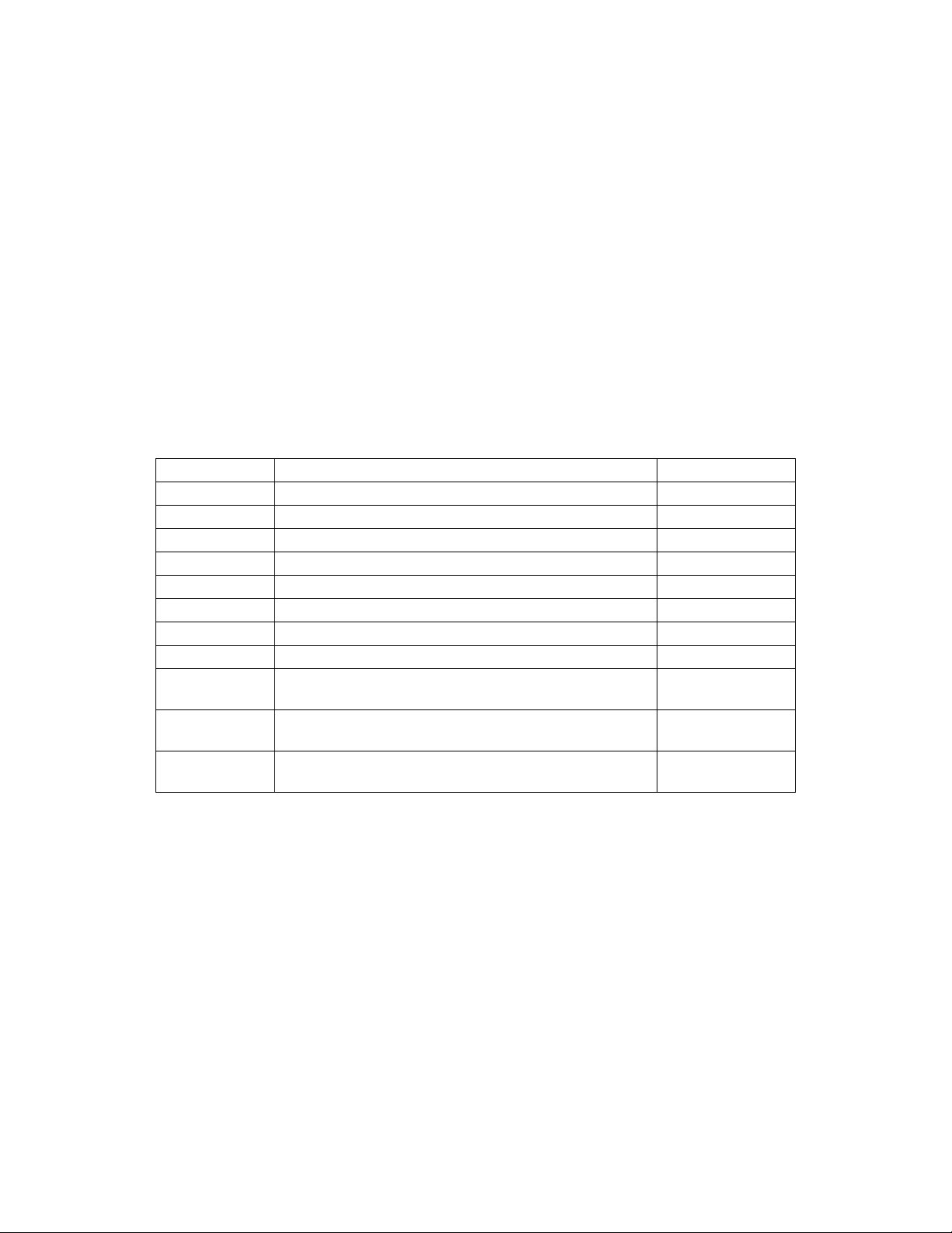
TABLE OF CONTENTS
SECTION 1. FEATURES AND SPECIFICATIONS.....................................................................................1
CONFIGURATIONS..................................................................................................................................1
STANDARD FEATURES...........................................................................................................................2
OPTION.....................................................................................................................................................2
RELATED DOCUMENTS..........................................................................................................................2
SPECIFICATIONS.....................................................................................................................................3
SECTION 2. INSTALLATION......................................................................................................................5
COMPONENTS.........................................................................................................................................5
Card Seated Switch..............................................................................................................................7
MECHANICAL MOUNTING ......................................................................................................................7
Side Mounting Pins...............................................................................................................................7
Side Mounting Slots..............................................................................................................................7
PCB MOUNTING POSTS..........................................................................................................................7
SMART CARD CONNECTOR...................................................................................................................7
Flex Pin Dimensions.............................................................................................................................9
Head Pin Connector .............................................................................................................................9
APPENDIX A. ENGINEERING DRAWINGS.............................................................................................11
TABLES and FIGURES
Figure 1-1. IntelliStripe 70, Hybrid Insertion Reader................................................................................... vi
Table 1-1. Part Numbers, Configurations, and Tracks.................................................................................1
Table 1-2. Specifications..............................................................................................................................3
Figure 2-1. Components of the IntelliStripe 70.............................................................................................6
Table 2-1. Pin List for Flex Cable.................................................................................................................8
Figure 2-2. Pin Orientation - Flex Cable Side of Smartcard Connector.......................................................8
Figure 2-3. Flex Pin Dimensions and Mating Connector .............................................................................9
Figure 2-4. Head Pin Connector ..................................................................................................................9
Table 2-2. 3-Track Head Pin Listing.............................................................................................................9
Table 2-3. Track 2, 3 Head Pin Listing.......................................................................................................10
Table 2-4. Track 1, 2 Head Pin Listing.......................................................................................................10
Figure A-1 Bottom Chassis Dimensions 1 .................................................................................................12
Figure A-2 Bottom Chassis Dimensions 2 .................................................................................................13
Figure A-3 Top Chassis Dimensions 1.......................................................................................................14
Figure A-3 Top Chassis Dimensions 2.......................................................................................................15
v
Page 6
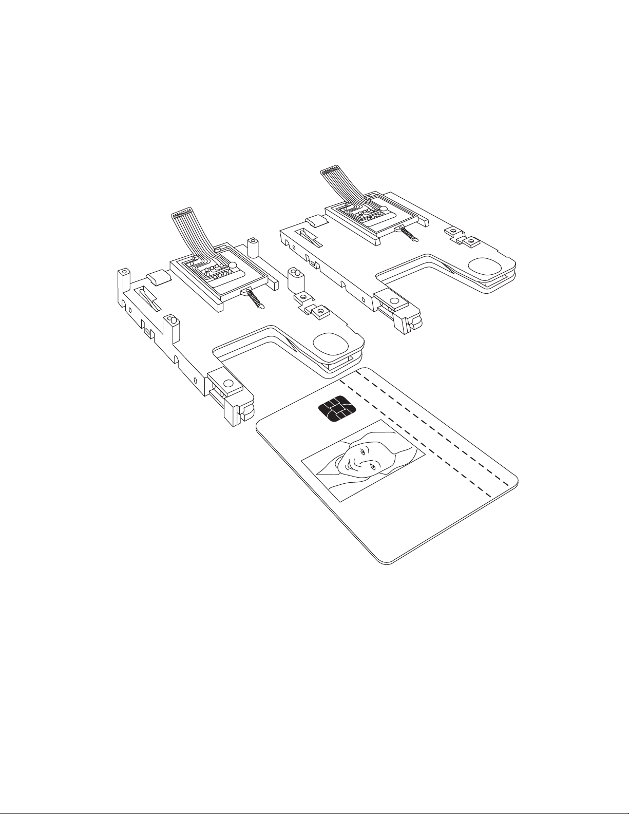
Without PCB
Mounting Posts
With PCB
Mounting Posts
Figure 1-1. IntelliStripe 70, Hybrid Insertion Reader
vi
Page 7
SECTION 1. FEATURES AND SPECIFICATIONS
The IntelliStripe 70 is a chassis-only hybrid insertion reader, which provides magstripe and
smartcard functionality. The chassis is not equipped with electronics, which are required to
complete the magstripe and smartcard interfaces.
The reader features a low-profile mechanical footprint which is ideally suited for integration into
POS terminals, payphones, vending machines, kiosks, and fuel pumps.
CONFIGURATIONS
The part numbers, configurations, and tracks for the IntelliStripe 70 Hybrid Insertion Reader are
shown in Table 1-1.
Table 1-1. Part Numbers, Configurations, and Tracks
Part Number Configuration Track Numbers
21170001 No side pins or flange, 8 SC contacts 1 & 2
21170002 Side pins, 8 SC contacts 2 & 3
21170003 Side pins, 8 SC contacts 1, 2, 3
21170004 No side pins or flange, 8 SC contacts 2 & 3
21170005 No side pins or flange, 8 SC contacts 1, 2, 3
21170006 No side pins, with extended flex cable 1, 2, 3
21170007 Side pins, 8 SC contacts 1 & 2
21170008 Side pins, 8 SC contacts with extended flex cable 1, 2, 3
21170009 No side pins, no PCB posts, 8 SC contacts with
extended flex cable
21170010 No side pins, no PCB Posts, 8 SC contacts with
extended flex cable, no head pin cap
21170012 Side pins, 8 SC contacts with extended flex cable;
Shift-Out IntelliHead
1, 2, 3
1, 2, 3
1, 2, 3
1
Page 8

IntelliStripe 70 Hybrid Insertion Reader
STANDARD FEATURES
Standard features of the IntelliStripe 70 are as follows:
The product will provide the following features:
• Compact mechanical footprint. Ideally suited for use with POS terminals
• For low profile application, chassis is offered with no PCB mounting posts
• Ability to support “No Pin” and “Side Pin” mounting options
• Chassis and smartcard contacts design meet EMV Level 1 electro-mechanical
requirements
• ISO 7816 8-contact smartcard connector with flex cable
• Landing switch on smartcard connector. (Detects card at rear/ landed)
• Spring-loaded side arm to hold the card securely in the smartcard position
• 2-track (track 1&2 and track 2&3) and 3-track magnetic stripe reading, using low profile
2-track and 3-track head-beam assemblies
• Beam mounted read head (Provides superior tracking of bowed or warped cards)
• Chassis Manufactured from polycarbonate glass-filled material and ABS.
• “Card flattening” feature, which ensures that bowed cards are funneled towards the
smartcard contacts
OPTION
The following option may be selected: Mag-stripe can be configured to support all popular track
combinations.
RELATED DOCUMENTS
The IntelliStripe 70, Hybrid Insertion Reader will read cards that meet the standards defined by
ISO (International Standards Organization):
ISO 7816 - Identification Cards – Integrated circuits with contacts
ISO 7811 - Identification Cards – Mag-stripe Cards, Tracks 1-3
ISO 7810 - Identification Cards – Physical Specifications (ID-1 Cards)
2
Page 9

Section 1. Features and Specifications
SPECIFICATIONS
The specifications of the Reader are listed in Table 1-2. The overall dimensions are shown in
Appendix A.
Table 1-2. Specifications
DATA FORMAT SPECIFICATIONS
Reader Configuration
Track 1,2
Track 2,3
Track 1,2,3
* ISO (International Standards Organization), ANSI (American National Standards Institute), AAMVA,
(American Association of Motor Vehicle Administrators)
Card Speed: 3 IPS (7.62cm/sec) to 50 IPS (127cm/sec)
Recording Method Two-frequency coherent phase (F2F)
Voltage Not Applicable
Current Not Applicable
Dimensions (no side pins)
Depth
Width
Height
Dimensions (side pins)
Depth
Width
Height
Dimensions (No PCB Posts)
Height
Weight: 45.3 g (1.6 oz)
Temperature
Operating:
Storage:
Humidity
Operating:
Storage:
Altitude
Operating:
Storage:
Data Format Specifications*
ISO/ANSI/AAMVA/210bpi on TK2 formats
ISO/ANSI/AAMVA formats
ISO/ANSI/AAMVA formats
OPERATIONAL
ELECTRICAL
MECHANICAL
103.8 mm (4.1”)
65.8 mm (2.59”)
21.8 mm (0.86”)
103.8 mm (4.1”)
73.7 mm (2.9”)
21.8 mm (0.86”)
18.5 mm (0.729”)
ENVIRONMENTAL
o
C to 70 oC (-13 oF to 158 oF)
-25
o
C to 70 oC (-40 oF to 158 oF)
-40
10% to 95% noncondensing
10% to 95% noncondensing
0-10,000 ft. (0-3,048 m.)
0-50,000 ft. (0-15,240 m.)
3
Page 10

IntelliStripe 70 Hybrid Insertion Reader
4
Page 11

SECTION 2. INSTALLATION
The Installation of the IntelliStripe 70 Hybrid Insertion Reader includes mechanical and
electrical connections.
COMPONENTS
The components of the IntelliStripe 70 are shown and Figure 2-1.
5
Page 12

IntelliStripe 70 Hybrid Insertion Reader
PCB Mounting
Landing
Switch
Smartcard
Flex Cable
Posts
Locator Pin
Card
Catch
Card
Seated
Switch
PCB Mounting
Posts
Mounting Slots
Locator Pin Card Orientation
Low-Profile Beam-Style
Head Mounting
96550033 rev B
6
7 Pin
Connector
Smartcard Contacts
On Landing Switch
Moulded-In
Mounting Pins
Figure 2-1. Components of the IntelliStripe 70
Page 13

Section 2. Installation
Card Seated Switch
A Card-Seated switch is operated when a card is fully inserted into the Reader (card is at the
fully rearward position). The Card-Seated switch is an integral feature of the Smartcard
Connector Block and detects when the card has properly “landed” (seated) on the smartcard
contacts. The card-seated signal at the interface I/O connector is normally open and is grounded
when the card is fully inserted into the Reader.
On insertion of the card, there may be some spurious transitions (mechanical switch bounce) at
the Card Seated output, which do not exceed 4 ms. These transitions occur before the ICC chip
contacts stabilize (stable contact with ICC pads) within a maximum of 40 ms from the stable
state of the Card Seated output.
The first transition from the Card Seated output on withdrawal of the card is guaranteed to occur
1 ms before the ICC contacts lift. During the period between the two events, the contact
resistance can increase to (but not exceed) 100 ohms for C1, C5, and C8 contacts, and 500 ohms
for C2, C3, C4, and C8 contacts. For C7 the limit is 700 ohms.
Subsequent to the first transition from the Card Seated sensor, there can be additional transitions
because of the mechanical bounce of the Card Seated switch contacts.
MECHANICAL MOUNTING
Mounting options for the Reader are as follows:
• Side Mounting Pins
• Side Mounting Slots
Side Mounting Pins
There are four molded pins; two are located on each side of the chassis. The holes are for M3 or
#4 self-tapping screws. Dimensions for mounting with pins are shown in Appendix A.
Side Mounting Slots
Four molded slots are available when pins are not provided. Dimensions for mounting with slots
are shown in Appendix A.
PCB MOUNTING POSTS
The PCB Mounting Posts are located on the upper side of the Reader. Mounting Posts may be
used for chassis or PCB mounting. The Posts are designed to accept M3 or #4 self- tapping
screws torqued to 4.0 in-lbs.
SMART CARD CONNECTOR
The IntelliStripe 70 contains a 10-pin smartcard connector with switch, which connects to the
user’s PCB assembly through a flex cable. The location of the flex cable is shown in previous
illustrations and identified in Figure 2-1.
7
Page 14

IntelliStripe 70 Hybrid Insertion Reader
Table 2-1 lists the I/O Flex Cable pin numbers, Signal names, and the I/O direction with respect
to the Reader (IN is in to the Reader, and OUT is out of the Reader). Figure 2-2 shows the pin
orientation of the flex cable. Pins are numbered from 1 to 10 as indicated in the illustration.
Table 2-1. Pin List for Flex Cable
Pin Number Signal Name I/O Direction
1 Card Seated* OUT
2 ICC-C8 Undefined**
3 ICC-C7 Data IN/OUT
4 ICC-C6 Programmable Power IN
5 ICC-C1 Power IN
6 ICC-C2 Reset IN
7 ICC-C5 Ground IN
8 ICC-C3 Clock IN
9 ICC-C5 Ground IN
10 ICC-C4 Undefined**
* Card Seated (Pin 1) is a normally-open switch, which connects to
Gnd when closed. The user design may need to provide an external
pull-up resistor.
** Signals ICC-C8 and -C4 (pins 2 and 10) are undefined by ISO 7816.
These contacts are often used with non-ISO memory-type cards.
25.4 mm
1.00 “
Pin 10
Pin 1
Figure 2-2. Pin Orientation - Flex Cable Side of Smartcard Connector
8
Page 15

Section 2. Installation
Flex Pin Dimensions
Dimensions for the flex cable are shown in Figure 2-3.
.433" + .004" -.002"
.039" (1.0 mm pitch)
.012" x .012"
Chamfer or Radius
2 Places
110
.039" +/- .006"
Termination Detail.
Foil Side Shown.
Mates with Molex
71220 (or equivalent)
Scale: None
Figure 2-3. Flex Pin Dimensions and Mating Connector
Head Pin Connector
The connector for the head pins is shown in Figure 2-4. The pin listings are shown in Table 2-2,
-3, and -4.
The mating connector is Molex 53048-0710.
Pin 1
Figure 2-4. Head Pin Connector
Table 2-2. 3-Track Head Pin Listing
Pin Signal Color
1 TK 1 Red
2 TK 1 Red
3 TK 2 Green
4 TK 2 Green
5 TK 3 Yellow
6 TK 3 Yellow
7 Gnd Black
9
Page 16

IntelliStripe 70 Hybrid Insertion Reader
Table 2-3. Track 2, 3 Head Pin Listing
Pin Signal Color
1 NC
2 NC
3 TK 2 Green
4 TK 2 Green
5 TK 3 Yellow
6 TK 3 Yellow
7 Gnd Black
Table 2-4. Track 1, 2 Head Pin Listing
Pin Signal Color
1 TK1 Red
2 TK1 Red
3 TK 2 Green
4 TK 2 Green
5 NC
6 NC
7 Gnd Black
10
Page 17

APPENDIX A. ENGINEERING DRAWINGS
Figures A-1 and A-2: Show dimensions for the bottom half of the IntelliStripe 70 chassis
Figures A-3 and A-4: Show dimensions for the top half of the IntelliStripe 70 chassis
11
Page 18

IntelliStripe 70 Hybrid Insertion Reader
12
Figure A-1 Bottom Chassis Dimensions 1
Page 19

Appendix A. Drawings
Figure A-2 Bottom Chassis Dimensions 2
13
Page 20

IntelliStripe 70 Hybrid Insertion Reader
14
Figure A-3 Top Chassis Dimensions 1
Page 21

Appendix A. Drawings
Figure A-3 Top Chassis Dimensions 2
15
 Loading...