

Page 1

INTELLISTRIPE 50
SMARTCARD INSERTION READER
TECHNICAL REFERENCE MANUAL
Manual Part Number 99875248 Rev 4
DECEMBER 2005
REGISTERED TO ISO 9001:2000
1710 Apollo Court
Seal Beach, CA 90740
Phone: (562) 546-6400
FAX: (562) 546-6301
Technical Support: (651) 415-6800
www.magtek.com
Page 2

Copyright© 2002-2005
MagTek®, Inc.
Printed in the United States of America
Information in this document is subject to change without notice. No part of this document may be
reproduced or transmitted in any form or by any means, electronic or mechanical, for any purpose,
without the express written permission of MagTek, Inc.
MagTek is a registered trademark of MagTek, Inc.
IntelliStripe is a registered trademark of MagTek, Inc.
REVISIONS
Rev Number Date Description
1 25 Nov 02 Initial Release
2 13 Mar 03 Front Matter: Agency Page, removed all agencies
except UL/CUL, replaced some fonts so manual
would print on all printers Sec 1: Configuration
table, changed all P/Ns.
3 13 Jun 03 Removed TTL throughout; Front Matter: added
ISO line to logo, changed Tech Support phone
number, added new warranty statement; Sec 2:
added flex cable drawing, Figure 2-3.
4 19 Dec 05 Front Matter: Replaced old Limited Warranty with
new Limited Warranty; Sec 1: Added new models:
21160110 and 21160119. Appendix B: Corrected
tables and titles of figures.
ii
Page 3

LIMITED WARRANTY
MagTek warrants that the products sold to Reseller pursuant to this Agreement will perform in accordance with
MagTek’s published specifications. This warranty shall be provided only for a period of one year from the date
of the shipment of the product from MagTek (the “Warranty Period”). This warranty shall apply only to the
original purchaser unless the buyer is authorized by MagTek to resell the products, in which event, this warranty
shall apply only to the first repurchase.
During the Warranty Period, should this product fail to conform to MagTek’s specifications, MagTek will, at its
option, repair or replace this product at no additional charge except as set forth below. Repair parts and
replacement products will be furnished on an exchange basis and will be either reconditioned or new. All replaced
parts and products become the property of MagTek. This limited warranty does not include service to repair
damage to the product resulting from accident, disaster, unreasonable use, misuse, abuse, customer’s negligence,
Reseller’s negligence, or non-MagTek modification of the product. MagTek reserves the right to examine the
alleged defective goods to determine whether the warranty is applicable.
Without limiting the generality of the foregoing, MagTek specifically disclaims any liability or warranty for
goods resold in other than MagTek’s original packages, and for goods modified, altered, or treated by customers.
Service may be obtained by delivering the product during the warranty period to MagTek (1710 Apollo Court,
Seal Beach, CA 90740). If this product is delivered by mail or by an equivalent shipping carrier, the customer
agrees to insure the product or assume the risk of loss or damage in transit, to prepay shipping charges to the
warranty service location and to use the original shipping container or equivalent. MagTek will return the product,
prepaid, via a three (3) day shipping service. A Return Material Authorization (RMA) number must accompany
all returns.
MAGTEK MAKES NO OTHER WARRANTY, EXPRESS OR IMPLIED, AND MAGTEK DISCLAIMS ANY
WARRANTY OF ANY OTHER KIND, INCLUDING ANY WARRANTY OF MERCHANTABILITY OR
FITNESS FOR A PARTICULAR PURPOSE.
EACH PURCHASER UNDERSTANDS THAT THE MAGTEK PRODUCT IS OFFERED AS IS. IF THIS
PRODUCT DOES NOT CONFORM TO MAGTEK’S SPECIFICATIONS, THE SOLE REMEDY SHALL BE
REPAIR OR REPLACEMENT AS PROVIDED ABOVE. MAGTEK’S LIABILITY, IF ANY, TO RESELLER
OR TO RESELLER’S CUSTOMERS, SHALL IN NO EVENT EXCEED THE TOTAL AMOUNT PAID TO
MAGTEK BY RESELLER UNDER THIS AGREEMENT. IN NO EVENT WILL MAGTEK BE LIABLE TO
THE RESELLER OR THE RESELLER’S CUSTOMER FOR ANY DAMAGES, INCLUDING ANY LOST
PROFITS, LOST SAVINGS OR OTHER INCIDENTAL OR CONSEQUENTIAL DAMAGES ARISING OUT
OF THE USE OF OR INABILITY TO USE SUCH PRODUCT, EVEN IF MAGTEK HAS BEEN ADVISED OF
THE POSSIBILITY OF SUCH DAMAGES, OR FOR ANY CLAIM BY ANY OTHER PARTY.
LIMITATION ON LIABILITY
EXCEPT AS PROVIDED IN THE SECTIONS RELATING TO MAGTEK’S LIMITED WARRANTY,
MAGTEK’S LIABILITY UNDER THIS AGREEMENT IS LIMITED TO THE CONTRACT PRICE OF THE
PRODUCTS.
MAGTEK MAKES NO OTHER WARRANTIES WITH RESPECT TO THE PRODUCTS, EXPRESSED OR
IMPLIED, EXCEPT AS MAY BE STATED IN THIS AGREEMENT, AND MAGTEK DISCLAIMS ANY
IMPLIED WARRANTY, INCLUDING WITHOUT LIMITATION ANY IMPLIED WARRANTY OF
MERCHANTABILITY OR FITNESS FOR A PARTICULAR PURPOSE.
MAGTEK SHALL NOT BE LIABLE FOR CONTINGENT, INCIDENTAL, OR CONSEQUENTIAL
DAMAGES TO PERSONS OR PROPERTY. MAGTEK FURTHER LIMITS ITS LIABILITY OF ANY KIND
WITH RESPECT TO THE PRODUCTS, INCLUDING ANY NEGLIGENCE ON ITS PART, TO THE
CONTRACT PRICE FOR THE GOODS.
MAGTEK’S SOLE LIABILITY AND BUYER’S EXCLUSIVE REMEDIES ARE STATED IN THIS SECTION
AND IN THE SECTION RELATING TO MAGTEK’S LIMITED WARRANTY.
iii
Page 4

UL/CUL
This product is recognized per Underwriter Laboratories and Canadian Underwriter Laboratories 1950.
iv
Page 5

TABLE OF CONTENTS
SECTION 1. FEATURES AND SPECIFICATIONS..................................................................................... 1
FEATURES...............................................................................................................................................
OPTIONS..................................................................................................................................................
CONFIGURATIONS .................................................................................................................................
MOUNTING FEATURES..........................................................................................................................
DEBRIS CLEARANCE..............................................................................................................................
SIDE LOAD SPRING................................................................................................................................
RELATED DOCUMENTS.........................................................................................................................
SPECIFICATIONS....................................................................................................................................3
1
1
2
2
2
2
2
SECTION 2. INSTALLATION......................................................................................................................
MOUNTING...............................................................................................................................................
No Flange.............................................................................................................................................
Small Flange.........................................................................................................................................
Large Flange.........................................................................................................................................
CABLE CONNECTION.............................................................................................................................
APPENDIX A. OPTIONS...........................................................................................................................
OPTIONAL FRONT GATE......................................................................................................................
APPENDIX B. ENGINEERING DRAWINGS.............................................................................................
FIGURES
7
7
7
7
8
9
11
11
13
Figure 1-1. IntelliStripe 50, Smartcard Insertion Reader with Small Flange...............................................
Table 1-1. Specifications..............................................................................................................................3
Figure 1-2. IntelliStripe 50, with Small Flange..............................................................................................
Figure 1-3. IntelliStripe 50, No Flange .........................................................................................................
Figure 1-4. IntelliStripe 50, Large Flange.....................................................................................................
Figure 2-1. Top View of IntelliStripe 50 Reader with Card...........................................................................
Figure 2-2. Bottom View of IntelliStripe 50 Reader with Card......................................................................
Table 2-2. Pin List for I/O Connector (J1) ....................................................................................................
Figure 2-3. Flex Connector Pin Dimensions and Mating Connector..........................................................
Figure A-1. Optional Front Gate.................................................................................................................
Table B-1. Part Numbers and Titles of Drawings.......................................................................................
Table B-2. Options, Choices, Codes..........................................................................................................
Figure B-1. I50 B1, M6, C1, SG (Page 1) ..................................................................................................
Figure B-2. I50 B1, M6, C1, SG (Page 2) ..................................................................................................
Figure B-3. I50 B1, M6, C1 (Page 1)..........................................................................................................
Figure B-4. I50 B1, M6, C1 (Page 2)..........................................................................................................
Figure B-5. I50 B1, M4, C1, SG (Page 1) ..................................................................................................
Figure B-6. I50 B1, M4, C1, SG (Page 2) ..................................................................................................
Figure B-7. I50 B1, M5, C1, SG (Page 1) ..................................................................................................
Figure B-8. I50 B1, M5, C1, SG (Page 2) ..................................................................................................
Figure B-9. I50 B1, M4, C1 (Page 1)..........................................................................................................
Figure B-10. I50 B1, M4, C1 (Page 2)........................................................................................................
Figure B-11. I50 B1, M5, C1 (Page 1)........................................................................................................
Figure B-12. I50 B1, M5, C1 (Page 2)........................................................................................................
Figure B-13. I50 B1, M6, C1, RT (Page 1).................................................................................................
Figure B-14. I50 B1, M6, C1, RT (Page 2).................................................................................................
Figure B-15. I50 M6, SG (INT FLEX) (Page 1)..........................................................................................
Figure B-16. I50 M6, SG (INT FLEX) (Page 2)..........................................................................................
TABLES
Table 1-1. Specifications..............................................................................................................................3
Table 2-2. Pin List for I/O Connector (J1) ....................................................................................................
Table B-1. Part Numbers and Titles of Drawings.......................................................................................
Table B-2. Options, Choices, Codes..........................................................................................................
vi
4
4
5
7
8
9
10
11
13
13
14
15
16
17
18
19
20
21
22
23
24
25
26
27
28
29
9
13
13
v
Page 6
vi
Figure 1-1. IntelliStripe 50, Smartcard Insertion Reader with Small Flange
Page 7

SECTION 1. FEATURES AND SPECIFICATIONS
The IntelliStripe 50® Smartcard Insertion Reader is a low-cost, high-reliability, half card,
smartcard only, reader for use in self-service kiosks and terminals. There is no onboard
intelligence; the device acts as a connector to a smartcard or memory card. Users must provid e
their own electronics and software to communicate with the card.
The location and features of the smartcard contacts are compliant with ISO 7816 and EMV
Level I mechanical specifications related to contact loading and contact force.
There are three types of mounting configurations for the Reader: no flange, small flange, and
large flange. Part numbers are listed under configurations, and other features and options are
listed below.
FEATURES
• Rated for 1,000,000 insertion cycles
• Small footprint compatible with most half-card readers
• Three different Chassis styles allow for optimized mounting and integration
• Vandal Resistant – Open chassis design provides superior debris clearance: “half card
dropout” and coins can be cleared from insert channel
• Durable – Manufactured from polycarbonate glass-filled material which meets UL-94VO
rating or better
• ISO 7816 8-contact smartcard connector with flex cable
• Side load spring pressure provided to keep the card from sliding away from smartcard
contacts
• Card Catch feature ensures that bowed cards are funneled towards the smartcard contacts
• 10-pin I/O connector at the rear of the unit
OPTIONS
• Front Card Gate prevents coins, dust, moisture, and debris, from entering the unit – opens
only when ISO-size card enters the unit
1
Page 8

IntelliStripe 50 Smartcard Insertion Reader
CONFIGURATIONS
Part Number Flange Mounting Options* Description
21160104 Small IntelliStripe 50, Small Flange, with front gate
21160105 Small IntelliStripe 50, Small Flange, without front gate
21160106 None IntelliStripe 50, No Flange, with front gate
21160107 Large IntelliStripe 50, Large Flange, with front gate
21160108 None IntelliStripe 50, No Flange, without front gate
21160109 Large IntelliStripe 50, Large Flange, without front gate
21160110 Small IntelliStripe 50, Small Flange, without front gate
21160119 Small IntelliStripe 50, Small Flange, with front gate
*See Section 2, Installation, for mounting configurations and dimensions.
MOUNTING FEATURES
The product supports 3 types of mounting configurations: no flange, small flange, large flange.
Part numbers for the configurations are listed above in Configurations.
The Reader chassis is mounted so the smartcard is presented with the chip up as viewed by the
user. The smartcard contacts are at the top of the card slot and face downward. This orientation
permits the debris clearance feature. (See Section 2.)
DEBRIS CLEARANCE
The Reader features an “open card slot” design, which allows most debris to fall free from the
Reader slot and is large enough to allow “half cards” to drop free from the Reader.
SIDE LOAD SPRING
The side-load spring applies constant pressure to the card, ensuring that the card remains
stationary when the user’s hand is removed from the card.
RELATED DOCUMENTS
The IntelliStripe 50 Smartcard Insertion Reader will interface with cards that meet the standards
defined by ISO (International Standards Organization):
ISO 7810 Identification Cards – Physical Specifications
ISO 7816-1, -2, -3 Identification Cards – Integrated circuits with contacts
2
Page 9

Section 1. Features and Specifications
SPECIFICATIONS
Table 1-1 lists the specifications. The overall dimensions and flange dimensions are shown in
Figures 1-2, 1-3, and 1-4.
Table 1-1. Specifications
MEDIA
Reference Standard ISO 7816 Cards
ELECTRICAL
Voltage Not Applicable Current Not Applicable
MECHANICAL
Dimensions
Large Flange
Depth
Width
Height
Small Flange
Depth
Width
Height
No Flange
Depth
Width
Height
Weight 82 g (2.90 oz.) Smartcard Contact Type Landing Smartcard Contact Reliability 1,000,000 insertions (minimum)
ENVIRONMENTAL
Temperature
Operating
Storage
Humidity
Operating
Storage
65.3mm (2.57”)
100.6 mm (3.96”)
30.2 mm (1.19”)
65.3mm (2.57”)
87.2 mm (3.28”)
21.1 mm (0.83”)
65.3mm (2.57”)
62.0 mm (2.41”)
21.1 mm (0.83”)
o
C to 70 oC (-13 oF to 158 oF)
-25
o
C to 80 oC (-40 oF to 176 oF)
-40
5% to 95% noncondensing
5% to 95% noncondensing
3
Page 10
IntelliStripe 50 Smartcard Insertion Reader
61.21
(2.41)
Side View
21.08
(.830)
65.3 = mm
(2.57) = inches
34.95 26.04x2
(1.376)
65.3
(2.57)
83.3
(3.28)
Ø3.30x2
(Ø.130x2)
12.19x2
(.480x2)
4.57x2
(.180x2)
74.0
(2.913)
Front View
Figure 1-2. IntelliStripe 50, with Small Flange
61.21
(1.025x2)
(2.41)
Top View
8.26x2
(.325x2)
10.03
(.395)
21.08
(.830)
4
Brass Inserts
M3x.5 (4 places)
(metric)
21.08
(.830)
Side View Front View
Figure 1-3. IntelliStripe 50, No Flange
61.2 = mm
(2.41) = inches
Page 11
Section 1. Features and Specifications
100.6
(3.96)
88.9x2
(3.501x2)
17.4
(.686)
19.08x2
(.751x2)
19.08x2 = mm
(.751x2) = inches
Front View
4.77x4
(.188x4)
30.2
(1.19)
Figure 1-4. IntelliStripe 50, Large Flange
5
Page 12

IntelliStripe 50 Smartcard Insertion Reader
6
Page 13

SECTION 2. INSTALLATION
The installation consists of
MOUNTING
No Flange
Shown in Section 1, Figure 1-3, the No Flange version is side mounted with four M3 (metric)
threaded inserts.
Small Flange
The small flange is shown in Section 1, Figure 1-2. The Small Flange version is front mounted,
and provides two holes of 3.30 mm (0.130”) diameter and two slots of 4.45 mm (0.180”) wide.
Various components of the IntelliStripe 50 Reader are shown in Figure 2-3 (below). The
orientation of the smartcard integrated circuit is with respect to the top view of the IntelliStripe
50 Reader.
10-Pin Connector
(8-Contact Smartcard Connector
1-Pin Card Seated Connector)
Flex Cable
ISO Contact Bracket
Gate Latch
Bracket
10-Pin I/O
Connector
PCB
Small Flange
Card Slot
Flange Slot (2)
Bracket
Spring
Flange Hole
Ø 3.30 mm (2 places)
Ø 0.130" (2 places)
Smartcard
Integrated
Circuit
Figure 2-1. Top View of IntelliStripe 50 Reader with Card
7
Page 14

IntelliStripe 50 Smartcard Insertion Reader
The bottom view of the Reader is shown in Figure 2-2.
Spring Activated
Side Arm
Front Gate
Card Catch
Flex
cable
Card Slot
ISO Smartcard
Contacts
Figure 2-2. Bottom View of IntelliStripe 50 Reader with Card
Large Flange
Shown in Section 1, Figure 1-4, the Large Flange version provides four slots 4.77 mm (0.188”)
wide.
8
Page 15

Section 2. Installation
(
)
CABLE CONNECTION
The PCB supports the use of a 10-pin, dual-row, 0.100” connector at the rear of the unit. (nonlocking). The pin list for the I/O Connector is shown in Table 2-2.
Table 2-2. Pin List for I/O Connector (J1)
Pin Number Signal Name Description
1 Landing Switch Signal
2 Landing Switch Ground*
3 SC Contact C1 Power
4 SC Contact C5 Ground
5 SC Contact C2 Reset
6 SC Contact C6 Program V
7 SC Contact C3 Clock
8 SC Contact C7 Data I/O
9 SC Contact C4 Reserved for Future Use**
10 SC Contact C8 Reserved for Future Use**
* Pin 2 of the I/O header is the ground side of the Landing switch.
It should be noted that pin 2 shares a common internal connection
to the ground signal on pin 4. See the diagram below for clarification.
** per ISO 7816
10-pin I/O Header
Landing Switch
Normally Open
Smartcard
Connector Block
User-defined
Host
Electrical
Interface
1
2
3
4
5
6
7
8
9
10
SC Contact C1
SC Contact C5
SC Contact C2
SC Contact C6
SC Contact C3
SC Contact C7
SC Contact C4
SC Contact C8
The pin list and mating connector for the flex cable are shown in Figure 2-3.
9
Page 16

IntelliStripe 50 Smartcard Insertion Reader
.433" + .004" -.002"
.039" (1.0 mm pitch)
.012" x .012"
Chamfer or Radius
2 Places
110
.039" +/- .006"
Termination Detail.
Foil Side Shown.
Mates with Molex
71220 (or equivalent)
Scale: None
Figure 2-3. Flex Connector Pin Dimensions and Mating Connector
10
Page 17

APPENDIX A. OPTIONS
OPTIONAL FRONT GATE
The optional Front Gate and its components are shown in Figure A-1.
Gate Return
Spring
Gate Latch
Spring Latch
Gate Arm Interlock
Figure A-1. Optional Front Gate
11
Page 18

IntelliStripe 50 Smartcard Insertion Reader
12
Page 19

APPENDIX B. ENGINEERING DRAWINGS
Table B-1 lists the drawing numbers, the title and the locations in this section.
Table B-2 lists the options, the choices of options, and the codes specified on the drawings.
Table B-1. Part Numbers and Titles of Drawings
Part Number Title Page Number
21160104 I50 B1, M6, C1 14
21160105 I50 B1, M6, C1 16
21160106 I50 B1, M4, C1, SG 18
21160107 I50 B1, M5, C1, SG 20
21160108 I50 B1, M4, C1 22
21160109 I50 B1, M5, C1 22
21160110 I50 B1, M6, C1, RT 26
21160119 I50 M6, SG (INT FLEX) 28
Table B-2. Options, Choices, Codes
Option Choice Code
Printed Circuit Board Yes B1
No
Mounting Bracket And Chassis Configuration No Pins Or Flange M4
Large Flange M5
Small Flange M6
Smartcard IC Contacts Eight Contacts C1
Eight Contacts W/Ext Flex C3
No Contacts
Security Gate Yes SG
No
Coating On PCB Conformal Coat CT
RTV On Connectors RT
No
Delete Pin Cap Yes NP
13
Page 20

IntelliStripe 50, Smartcard Insertion Reader
14
Figure B-1. I50 B1, M6, C1, SG (Page 1)
Page 21

Appendix B. Engineering Drawings
Figure B-2. I50 B1, M6, C1, SG (Page 2)
15
Page 22

IntelliStripe 50, Smartcard Insertion Reader
16
Figure B-3. I50 B1, M6, C1 (Page 1)
Page 23

Appendix B. Engineering Drawings
Figure B-4. I50 B1, M6, C1 (Page 2)
17
Page 24

IntelliStripe 50 Smartcard Insertion Reader
18
Figure B-5. I50 B1, M4, C1, SG (Page 1)
Page 25

Appendix B. Engineering Drawings
Figure B-6. I50 B1, M4, C1, SG (Page 2)
19
Page 26

IntelliStripe 50, Smartcard Insertion Reader
20
Figure B-7. I50 B1, M5, C1, SG (Page 1)
Page 27

Appendix B. Engineering Drawings
Figure B-8. I50 B1, M5, C1, SG (Page 2)
21
Page 28

IntelliStripe 50, Smartcard Insertion Reader
22
Figure B-9. I50 B1, M4, C1 (Page 1)
Page 29

Appendix B. Engineering Drawings
Figure B-10. I50 B1, M4, C1 (Page 2)
23
Page 30

IntelliStripe 50, Smartcard Insertion Reader
24
Figure B-11. I50 B1, M5, C1 (Page 1)
Page 31

Appendix B. Engineering Drawings
Figure B-12. I50 B1, M5, C1 (Page 2)
25
Page 32

IntelliStripe 50, Smartcard Insertion Reader
26
Figure B-13. I50 B1, M6, C1, RT (Page 1)
Page 33

Appendix B. Engineering Drawings
Figure B-14. I50 B1, M6, C1, RT (Page 2)
27
Page 34
IntelliStripe 50, Smartcard Insertion Reader
28
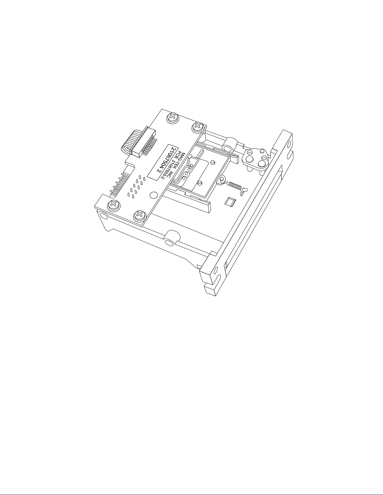
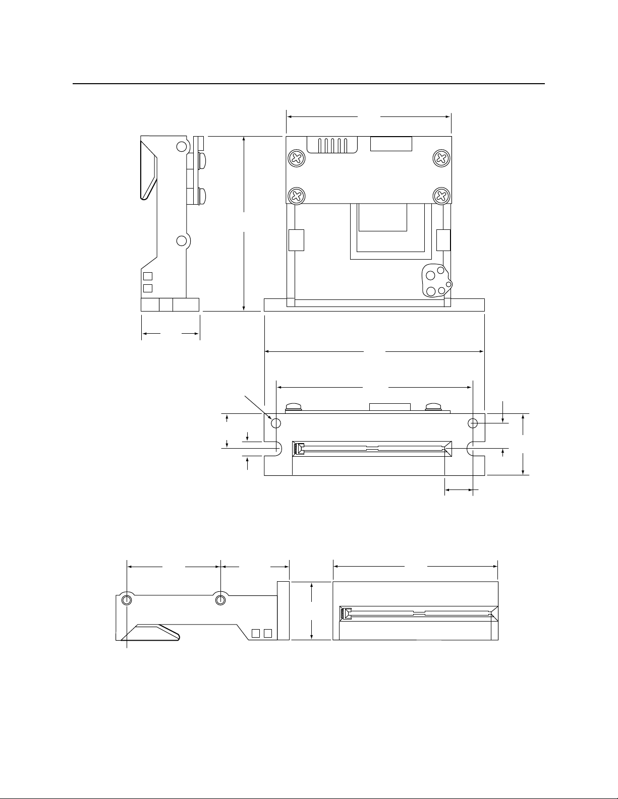
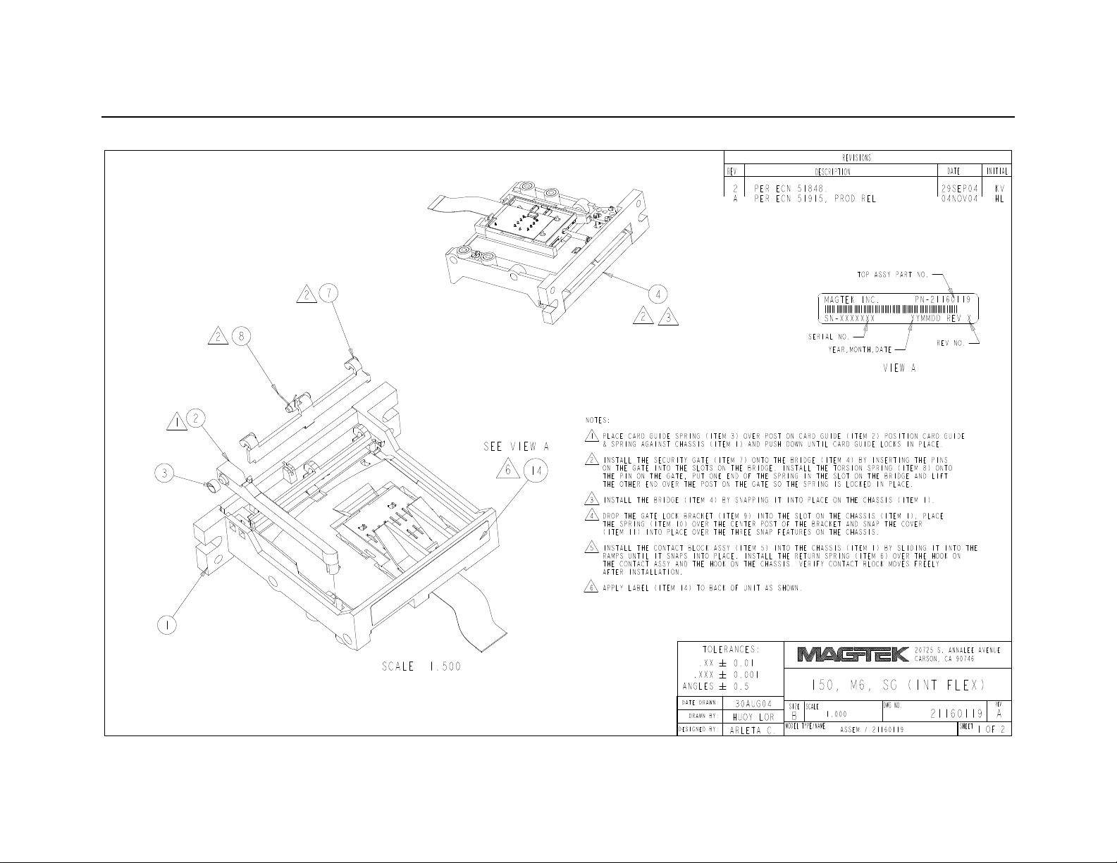
Figure B-15. I50 M6, SG (INT FLEX) (Page 1)
Page 35

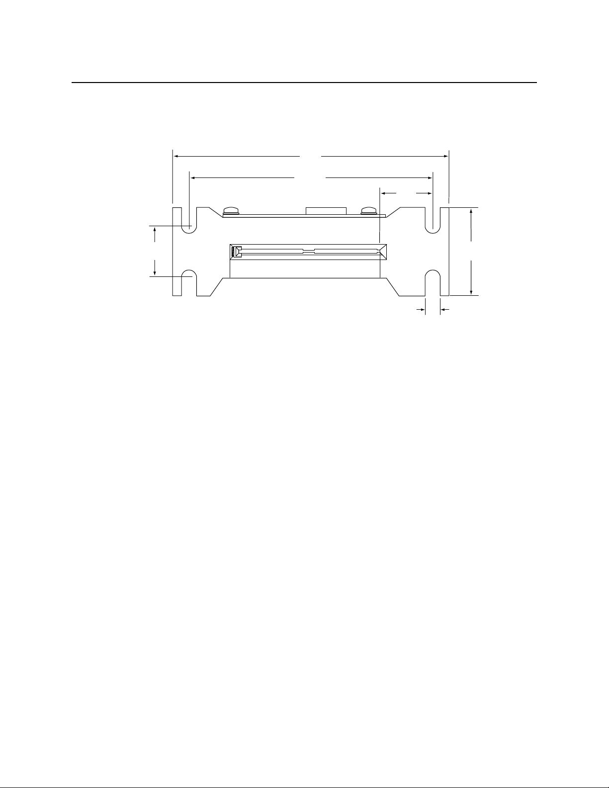
Appendix B. Engineering Drawings
Figure B-16. I50 M6, SG (INT FLEX) (Page 2)
29
Page 36

IntelliStripe 50, Smartcard Insertion Reader
30
 Loading...