

Page 1

IntelliStripe 350
DESKTOP MOTORIZED READER
TECHNICAL REFERENCE MANUAL
Manual Part Number: 99875179 Rev 6
FEBRUARY 2007
REGISTERED TO ISO 9001:2000
1710 Apollo Court
Seal Beach, CA 90740
Phone: (562) 546-6400
FAX: (562) 546-6301
Technical Support: (651) 415-6800
www.magtek.com
Page 2

Copyright© 2000-2007
MagTek®, Inc.
Printed in the United States of America
Information in this document is subject to change without notice. No part of this document may be
reproduced or transmitted in any form or by any means, electronic or mechanical, for any purpose,
without the express written permission of MagTek, Inc.
MagTek is a registered trademark of MagTek, Inc.
IntelliStripe is a registered trademark of MagTek, Inc.
REVISIONS
Rev Number Date Notes
1 16 Jan 01 Initial Release
2 12 Feb 01 Figure 1-2: added overall dimension
(7.125”), corrected other dimension (“7.11” to “6.125”).
3 16 Aug 01 Front Matter: Changed Warranty Address to
20801.Changed Agency page from CE Class B to Class A.
Editorial Correction To UL/CUL. Added EMV, Level 1.
Section 2: Table 2-1, Changed TRX to TXD.
4 2 May 02 Added JIS to Specifications; added Smartcard functions.
5 27 May 03 Front Matter: added ISO line to logo, changed Tech
Support phone number, added new warranty statement.
6 14 Feb 07 Added new model 16050313; removed RS-232 cable from
unit
ii
Page 3

LIMITED WARRANTY
MagTek warrants that the products sold to Reseller pursuant to this Agreement will perform in accordance with
MagTek’s published specifications. This warranty shall be provided only for a period of one year from the date
of the shipment of the product from MagTek (the “Warranty Period”). This warranty shall apply only to the
original purchaser unless the buyer is authorized by MagTek to resell the products, in which event, this warranty
shall apply only to the first repurchase.
During the Warranty Period, should this product fail to conform to MagTek’s specifications, MagTek will, at its
option, repair or replace this product at no additional charge except as set forth below. Repair parts and
replacement products will be furnished on an exchange basis and will be either reconditioned or new. All replaced
parts and products become the property of MagTek. This limited warranty does not include service to repair
damage to the product resulting from accident, disaster, unreasonable use, misuse, abuse, customer’s negligence,
Reseller’s negligence, or non-MagTek modification of the product. MagTek reserves the right to examine the
alleged defective goods to determine whether the warranty is applicable.
Without limiting the generality of the foregoing, MagTek specifically disclaims any liability or warranty for
goods resold in other than MagTek’s original packages, and for goods modified, altered, or treated by customers.
Service may be obtained by delivering the product during the warranty period to MagTek (1710 Apollo Court,
Seal Beach, CA 90740). If this product is delivered by mail or by an equivalent shipping carrier, the customer
agrees to insure the product or assume the risk of loss or damage in transit, to prepay shipping charges to the
warranty service location and to use the original shipping container or equivalent. MagTek will return the product,
prepaid, via a three (3) day shipping service. A Return Material Authorization (RMA) number must accompany
all returns.
MAGTEK MAKES NO OTHER WARRANTY, EXPRESS OR IMPLIED, AND MAGTEK DISCLAIMS ANY
WARRANTY OF ANY OTHER KIND, INCLUDING ANY WARRANTY OF MERCHANTABILITY OR
FITNESS FOR A PARTICULAR PURPOSE.
EACH PURCHASER UNDERSTANDS THAT THE MAGTEK PRODUCT IS OFFERED AS IS. IF THIS
PRODUCT DOES NOT CONFORM TO MAGTEK’S SPECIFICATIONS, THE SOLE REMEDY SHALL BE
REPAIR OR REPLACEMENT AS PROVIDED ABOVE. MAGTEK’S LIABILITY, IF ANY, TO RESELLER
OR TO RESELLER’S CUSTOMERS, SHALL IN NO EVENT EXCEED THE TOTAL AMOUNT PAID TO
MAGTEK BY RESELLER UNDER THIS AGREEMENT. IN NO EVENT WILL MAGTEK BE LIABLE TO
THE RESELLER OR THE RESELLER’S CUSTOMER FOR ANY DAMAGES, INCLUDING ANY LOST
PROFITS, LOST SAVINGS OR OTHER INCIDENTAL OR CONSEQUENTIAL DAMAGES ARISING OUT
OF THE USE OF OR INABILITY TO USE SUCH PRODUCT, EVEN IF MAGTEK HAS BEEN ADVISED OF
THE POSSIBILITY OF SUCH DAMAGES, OR FOR ANY CLAIM BY ANY OTHER PARTY.
LIMITATION ON LIABILITY
EXCEPT AS PROVIDED IN THE SECTIONS RELATING TO MAGTEK’S LIMITED WARRANTY,
MAGTEK’S LIABILITY UNDER THIS AGREEMENT IS LIMITED TO THE CONTRACT PRICE OF THE
PRODUCTS.
MAGTEK MAKES NO OTHER WARRANTIES WITH RESPECT TO THE PRODUCTS, EXPRESSED OR
IMPLIED, EXCEPT AS MAY BE STATED IN THIS AGREEMENT, AND MAGTEK DISCLAIMS ANY
IMPLIED WARRANTY, INCLUDING WITHOUT LIMITATION ANY IMPLIED WARRANTY OF
MERCHANTABILITY OR FITNESS FOR A PARTICULAR PURPOSE.
MAGTEK SHALL NOT BE LIABLE FOR CONTINGENT, INCIDENTAL, OR CONSEQUENTIAL
DAMAGES TO PERSONS OR PROPERTY. MAGTEK FURTHER LIMITS ITS LIABILITY OF ANY KIND
WITH RESPECT TO THE PRODUCTS, INCLUDING ANY NEGLIGENCE ON ITS PART, TO THE
CONTRACT PRICE FOR THE GOODS.
MAGTEK’S SOLE LIABILITY AND BUYER’S EXCLUSIVE REMEDIES ARE STATED IN THIS SECTION
AND IN THE SECTION RELATING TO MAGTEK’S LIMITED WARRANTY.
........................................................................................... iii
Page 4

FCC WARNING STATEMENT
This equipment has been tested and found to comply with the limits for a Class A digital device, pursuant to Part
15 of FCC Rules. These limits are designed to provide reasonable protection against harmful interference when
the equipment is operated in a commercial environment. This equipment generates, uses, and can radiate radio
frequency energy and, if not installed and used in accordance with the instruction manual, may cause harmful
interference to radio communications. Operation of this equipment in a residential area is likely to cause harmful
interference in which case the user will be required to correct the interference at his own expense.
FCC COMPLIANCE STATEMENT
This device complies with Part 15 Of The FCC Rules. Operation of this device is subject to the following two
conditions: (1) This device may not cause harmful interference. And (2) This device must accept any interference
received, including interference that may cause undesired operation.
CANADIAN DOC STATEMENT
This digital apparatus does not exceed the Class A limits for radio noise for digital apparatus set out in the Radio
Interference Regulations of the Canadian Department of Communications.
Le présent appareil numérique n’émet pas de bruits radioélectriques dépassant les limites applicables aux
appareils numériques de las classe A prescrites dans le Réglement sur le brouillage radioélectrique édicté par les
ministère des Communications du Canada.
CE STANDARDS
Testing for compliance to CE requirements was performed by an independent laboratory. The unit under test was
found compliant to Class A.
UL/CSA
This product is recognized per Underwriter Laboratories and Canadian Underwriter Laboratories 1950.
EMVCo APPROVAL STATEMENT
EMVCo approval of the interface module (IFM) contained in this Terminal shall mean only that the IFM has been
tested in accordance with the EMV Level 1 Specifications, Version 3.1.1, as of the date of testing. EMVCo
approval does not under any circumstances include any endorsement or warranty regarding the completeness of
the approval process or the functionality, quality or performance of any particular product or service. EMVCo
does not warrant any products or services provided by third parties. EMVCo approval does not under any
circumstances include or imply any product warranties from EMVCo, including, without limitation, any implied
warranties of merchantability, fitness for purpose, or non-infringement, all of which are expressly disclaimed
by EMVCo. All rights and remedies regarding products and services, which have received EMVCo approval,
shall be provided by the party providing such products or services, and not by EMVCo.
iv
Page 5

TABLE OF CONTENTS
SECTION 1. FEATURES AND SPECIFICATIONS.....................................................................................1
CONFIGURATION....................................................................................................................................1
STANDARD FEATURES..........................................................................................................................1
SOFTWARE ACCESSORIES...................................................................................................................2
RELATED DOCUMENTS.........................................................................................................................2
SMART CARD INTERFACE.....................................................................................................................3
MAGNETIC STRIPE READER.................................................................................................................3
FLASH UPGRADABLE.............................................................................................................................3
INTERFACE..............................................................................................................................................3
SPECIFICATIONS....................................................................................................................................3
SECTION 2. INSTALLATION......................................................................................................................7
COMPONENTS ........................................................................................................................................7
PLACEMENT AND CABLE CONNECTIONS...........................................................................................8
REAR PANEL ...........................................................................................................................................9
SECTION 3. OPERATION AND MAINTENANCE ....................................................................................11
OPERATION...........................................................................................................................................11
MAINTENANCE......................................................................................................................................11
FIGURES and TABLES
FIGURE 1-1. INTELLISTRIPE 350.............................................................................................................VI
TABLE 1-1. SPECIFICATIONS...................................................................................................................4
FIGURE 1-2. INTELLISTRIPE 350 DIMENSIONS......................................................................................5
FIGURE 2-1. INTELLISTRIPE 350 COMPONENTS...................................................................................7
FIGURE 2-2. I/O CABLE WITH PIN LOCATIONS, P/N 16051412.............................................................8
TABLE 2-1. PIN LIST FOR I/O CABLE ......................................................................................................8
FIGURE 2-3. POWER SUPPLY AND AC CABLE......................................................................................9
FIGURE 2-4. REAR PANEL – RS-232 CONNECTION ..............................................................................9
FIGURE 2-5. REAR PANEL – USB CONNECTION.................................................................................10
FIGURE 3-1. EJECTOR ROD REMOVAL ................................................................................................12
FIGURE 3-2. CARD REMOVAL WITH EJECTOR ROD...........................................................................13
.............................................................................................v
Page 6
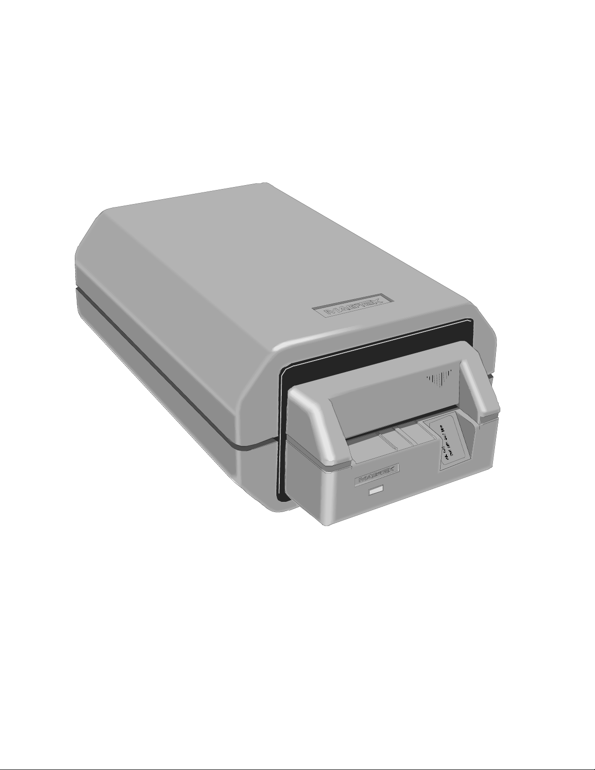
Figure 1-1. IntelliStripe 350
vi
Page 7

SECTION 1. FEATURES AND SPECIFICATIONS
The IntelliStripe 350, Desktop Motorized Reader, can read the mag-stripe data from financial
cards and drivers licenses, as well as provide ISO 7816/ EMV level 1 support for communicating
to T=0, T=1 Smartcards. Support for many popular Memory cards is also provided.
The Reader communicates with a Host via an RS-232 serial interface, and uses a proprietary
MCP protocol and command set, which has been developed by MagTek. Windows Drivers for
the MCP protocol are available and can support most Windows operating systems.
CONFIGURATION
Part numbers and descriptions for the basic configuration are shown in the table below. All extra
items must be ordered separately.
Part
Number
16050313 IntelliStripe 350, 3TK, C Bezel, RS-232 & USB Interface, Stripe
Down, Chip Up, EMV Compliant, cables ordered separately.
16051412 RS-232 I/O Cable, 7-pin connector connects to host 9-pin
connector with 12V/Ground connector for Power Supply.
16051433 USB Cable, 6’ MagTek Gray
64300080 Power Supply, 100V through 240V regulated with 2.5mm plug.
71100001 AC power cord, P/N is for use in North America. Other users must
supply their own cord, or contact MagTek for international cords.
STANDARD FEATURES
Standard features of the IntelliStripe 350 are as follows:
• Motorized transport
• RS-232 and USB interface
• Status LED
• Flash upgradable
• 8 Smart Card Contacts for reading ISO 7816 contact locations
• Supports all popular magnetic stripe track combinations
• Front Card Gate prevents coins, dust, moisture, and debris from entering the unit – gate
resists opening except when ISO-size card enters the unit.
Description
1
Page 8

IntelliStripe 350, Desktop Motorized Reader
SOFTWARE ACCESSORIES
The following Software Modules may be required and will assist in the development of
application software. In addition, this software can provide an initial test platform for checkout
of the IntelliStripe 350.
• IntelliStripe Picture Demo with MCP Driver:
P/N 30037435 (Floppy Disks) or P/N 99510015 (Web Release)
This software will install both a Demo program and the MCP driver.
The Demo program is useful for initial checkout of the Reader’s functionality. The
MCP driver is recommended for use as the communications interface on Windows
based host systems. Application programmers can interface to the MCP driver via a
MagTek defined API.
• Source Code for Picture Demo Program:
P/N 30037436
Visual Basic 6.0 source code for the Picture Demo program.
This will be useful to Application Programmers, as it shows examples of how to
interface with the MCP drivers and how to use the various commands.
• MCP Utility Program:
P/N 30037442 (Floppy Disks) or P/N 99510020 (Web Release)
This is a utility program that interfaces with the MCP driver, and allows engineers to
send commands directly to the Reader per the defined MagTek Command Set. This is
useful for gaining an understanding of the commands used with the Reader. (Note:
This utility requires that the MagTek MCP drivers be previously installed.)
RELATED DOCUMENTS
This document, P/N 99875179, is from a hardware perspective only. Other documents that cover
the command set, communications protocol, and API (Application Program Interface) are as
follows:
Part Number Title
99875163 MCP, Serial Transport Protocol, Reference Manual
99875164 Communication Protocol, Driver Reference Manual
99875168 IntelliStripe 320, Command Reference Manual
2
Page 9

Section 1. Features and Specifications
SMART CARD INTERFACE
The Reader can provide connections to ICC contacts as defined by ISO 7816 specifications. The
Reader supports ISO7816 T=0 and T=1 cards not requiring V
, with a speed range of 9600 bps
PP
to 115200 bps. It also supports a variety of common memory card types. See IntelliStripe 320
Command Reference Manual, Part Number 99875168, for more details.
MAGNETIC STRIPE READER
The Reader can read up to three tracks of magnetic stripe card data. See IntelliStripe 320
Command Reference Manual, Part Number 99875168, for more details.
FLASH UPGRADABLE
The unit's firmware is in-system Flash Upgradable. This allows the unit’s firmware to be
upgraded when required.
INTERFACE
The unit communicates to the host through either a USB or an RS-232 interface. For RS-232,
the device uses 8 data bits, 1 stop bit, even parity. The unit can automatically sync to baud rates
9600, 14400, 19200, 28800 38400, and 57600. See MCP Driver Reference Manual, Part
Number 99875164, and MCP Serial Transport Protocol Reference Manual, Part Number
99875163, for more details.
SPECIFICATIONS
Specifications for the Reader are listed in Table 1-1. Overall dimensions of the unit are shown in
Figure 1-2.
3
Page 10

IntelliStripe 350, Desktop Motorized Reader
Table 1-1. Specifications
DATA FORMAT SPECIFICATIONS
Reader Configuration
Mag-Stripe Functions
Track 1,2,3 only
Smartcard Functions
* ISO (International Standards Organization), ANSI (American National Standards Institute), AAMVA
(American Association of Motor Vehicle Administrators), JIS (Japanese Industri al Standard)
Card Speed: 10 IPS (25,4 cm/sec) typical
Recording Method: Two-frequency coherent phase (F2F)
MTBF:
Electronics
Head
SC Contacts
Input Voltage
Current
Dimensions:
Length
Width
Height
Cable Length (16051412)
Power Supply Cable Length
(64300080)
Power Cord (North American
100-240V) (P/N 71100001)
Weight:
Reader with Cable
Power Supply
AC Cord
Temperature
Operating
Storage
Humidity
Operating
Storage
Altitude
Operating
Storage
Data Format Specifications*
ISO/ANSI/AAMVA/JIS formats
ISO 7810, 7811, JIS x 6302 Type 2
ISO 7816 T=0 and T=1 protocols, many popular memory cards
EMVCo Level 1 Approval
OPERATIONAL
125,000 hours
1,000,000 passes (500,000 Insertion Cycles)
1,000,000 passes
ELECTRICAL
12.0 VDC ± 5%
1.5 A max
170 mA typical (with motor off)
MECHANICAL
7.125” (181.0 mm)
4.56" (115.82 mm)
2.85" (72.40 mm)
6’ (1.83 m)
6’ 4” (1.93 m)
7’ 6” (2.28 m)
2 lb 5.33oz (1.05 kg)
6.4 oz (0.2 kg)
6.4 oz (0.2 kg)
ENVIRONMENTAL
o
F to 122 oF (0 oC to 50 oC)
32
o
F to 158 oF (-40 oC to70 oC)
-40
10% to 95% noncondensing
10% to 95% noncondensing
0 to 10,000 ft. (0 to 3,048 m)
0 to 50,000 ft. (0 to 15,240 m)
4
Page 11

Section 1. Features and Specifications
T op Vie w
Front View
4.56"
(115.82 mm)
7.125"
6.125"
(155.6 mm)
2.85"
(72.40 mm)
(181.0 mm)
Figure 1-2. IntelliStripe 350 Dimensions
5
Page 12

IntelliStripe 350, Desktop Motorized Reader
6
Page 13

SECTION 2. INSTALLATION
The installation of the IntelliStripe 350 Desktop Motorized Reader consists of placing the unit on
a flat surface, plugging the I/O connector into the host serial port, and plugging the Power
Supply into the I/O cable and into a wall receptacle.
COMPONENTS
Components of the unit for installation are shown in Figure 2-1.
Power Supply And Cable
I/O Cable To
IntelliStripe 350
AC Cable
9 Pin Connector
To Host
AC Cable
Upper Cover
Lower Cover
Screw Slots (4) For
Retaining Upper
And Lower Covers
Ejector Rod
Bottom View
Two Of Four
Foot Pads
LED
Figure 2-1. IntelliStripe 350 Components
3 Prong Connector
Magnetic Stripe
Down And
T o The Right
7
Page 14
IntelliStripe 350, Desktop Motorized Reader
PLACEMENT AND CABLE CONNECTIONS
Refer to Figure 2-1, and place and connect the IntelliStripe 350 cabling as follows:
Ensure power to the PC is off.
1. Place the unit on a smooth flat surface convenient for operation.
2. Connect the 9-pin I/O connector to the PC.
3. Connect the 12 V power supply plug into the I/O cable.
4. Connect the AC cable into a wall receptacle.
5. Turn power on to the PC.
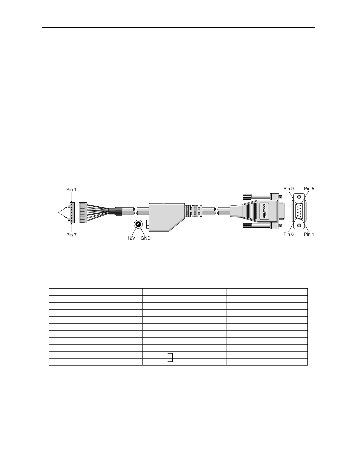
The I/O cable is shown in Figure 2-2 and the Pin List is shown in Table 2-1
Locking
Tabs
Figure 2-2. I/O Cable with Pin Locations, P/N 16051412
Table 2-1. Pin List for I/O Cable
Molex 7 Pin (51055-0700) DB-9 Female 2.5mm Power Jack
Pin Number Signal Name Pin Number Signal Name
1 TXD 2 RXD
2 +12V CENTER PIN +12V
3 PWR GND SHELL GND
4 RXD 3 TXD
5 RTS 8 CTS
6 CTS 7 RTS
7 SIGNAL GND 5 GND
6 DSR
4 DTR
8
Page 15
Section 2. Installation
or
g
N
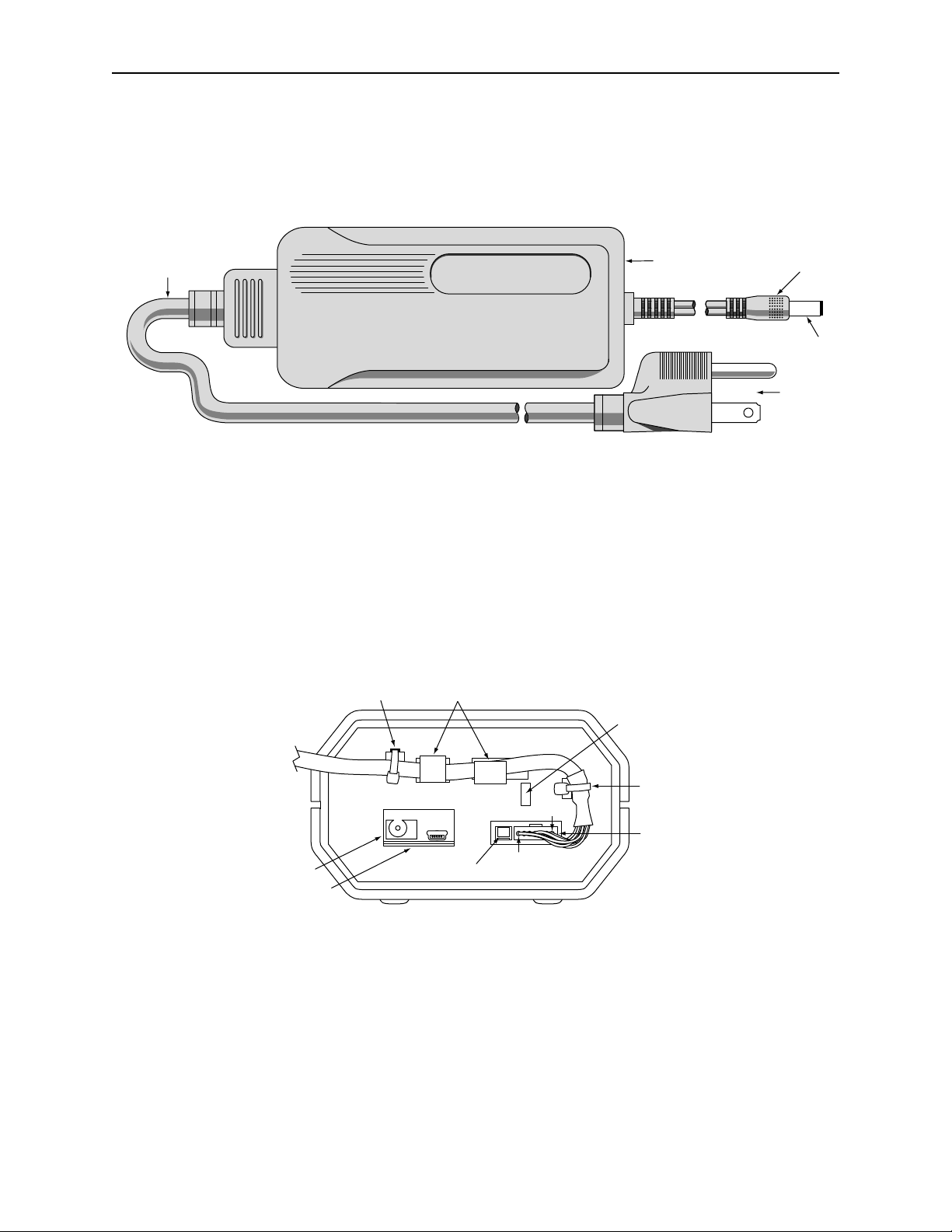
The Power Supply, P/N 64300080, 100V−240V regulated, 12VDC, with 2.5 mm plug is shown
in Figure 2-3. The AC power cord, P/N 71100001, is for use in North America. Other users must
supply their own AC cord, or contact MagTek for international cords.
orth American
100V–240V
Power Cord
Auto Range
Power Supply
12VDC Plu
GND
3 Prong
Connect
Figure 2-3. Power Supply and AC Cable.
REAR PANEL
The Rear Panel is shown in Figure 2-4 (for the RS-232 connection) and Figure 2-5 (for the USB
connection). The cables and tie wraps must be ordered as separate line items when ordering the
reader. For the RS-232 configuration, the power connector can either be connected to the rear of
the reader or into the power jack on the RS-232 cable.
Tie Wrap
Cable Clamps
Slot For Ejector Rod
To Remove Cards
Tie Wrap
Pin 1
7-Pin
Connector
Power Connector
USB Connector
Factory
Use Only
Back View
Pin 7
Figure 2-4. Rear Panel – RS-232 Connection
9
Page 16

IntelliStripe 350, Desktop Motorized Reader
Slot For Ejector Rod
USB Connector
Power Connector
To Remove Cards
7-Pin
Connector
Back View
Factory Use Only
Figure 2-5. Rear Panel – USB Connection
10
Page 17

SECTION 3. OPERATION AND MAINTENANCE
The operation of the unit includes inserting and removing the card. Maintenance includes
keeping the unit clean and removing jammed cards from the unit.
OPERATION
The card is inserted with the magnetic stripe down and to the right as illustrated in Figure 2-1.
Remove the card when unit ejects it. Perform any tasks on the PC as directed. The LED gives
status or direction as defined by the institution.
MAINTENANCE
Preventive maintenance includes cleaning the unit periodically with a lint-free cloth. The
cleaning schedule depends on how clean or dirty the environment is.
Corrective maintenance includes removing the card in case of power failure or card jam. In most
cases, resetting the unit will cause the card to automatically eject the card. To reset the unit
unplug the Power Supply connector (Figure 2-3) from the I/O connector and plug it back in.
If the card does not automatically eject, the card may be pushed out with a special tool, the
Ejector Rod, which is located on the bottom of the unit. The Rod is inserted into a slot in the
back of the unit, shown in Figure 3-2.
11
Page 18

IntelliStripe 350, Desktop Motorized Reader
d
To remove a jammed card proceed as follows:
1. Remove the Ejector Rod by sliding it from under the retaining tabs as shown in Figure 3-1.
Foot Pads (4)
Ejector Ro
Pull Out Ejector Rod
Agency
Approvals
Serial
Number
Sticker
Notch
Bottom View
Figure 3-1. Ejector Rod Removal
2. Look into the slot in the back of the unit, shown in Figure 3-2, to see the jammed card. This
will show the approximate position where the notch on the Ejector Rod will be inserted.
12
Page 19

Section 3. Operation and Maintenance
2
1.Observe Position
Of Jammed Card.
. Insert Rod Into Slot.
Reposition Until Card
Is In Notch In Rod.
3.Push Rod Until Card
Appears In Front.
Then Pull Card Out.
Back View
Figure 3-2. Card Removal with Ejector Rod
3. Insert the Rod into the slot as shown in Figure 3-2.
4. Reposition as required until the card is in the notch.
5. Push the Rod until the card appears in the front, then pull it out.
13
Page 20

IntelliStripe 350, Desktop Motorized Reader
14
 Loading...