

Page 1

™
IntelliStripe 310
MOTORIZED READER
TECHNICAL REFERENCE MANUAL
Manual Part Number: 99875216-4
MAY 2003
REGISTERED TO ISO 9001:2000
1710 Apollo Court
Seal Beach, CA 90740
Phone: (562) 546-6400
FAX: (562) 546-6301
Technical Support: (651) 415-6800
Page 2

www.magtek.com
ii
Page 3

Copyright 2000-2005
©
MagTek®, Inc.
Printed in the United States of America
Information in this document is subje
ct to change without notice. No part of this document may be
reproduced or transmitted in any form or by any means, electronic or mechanical, for any purpose,
without the express written permission of MagTek, Inc.
MagTek is a registered trademark of MagTek, Inc.
IntelliStripe is a registered trademark of MagTek, Inc.
REVISIONS
Rev Number Date Notes
1 26 Feb 02 Initial Release
2 2 May 02 Section 1: Added JIS to Specifications
3 24 Feb 02 Section 1: Added “A” Bezel to Configurations table
4 9 May 03 Front Matter: Added ISO line to logo, changed Tech Support phone
number, added new warranty statement; Sec 2: Changed converted
values in Figures 2-3, 2-4, 2-5, and 2-6.
iii
Page 4

LIMITED WARRANTY
MagTek warrants that the products sold to Reseller pursuant to this Agreement will perform in accordance with
MagTek’s published specifications. This warranty shall be provided only for a period of one year from the date
of the shipment of the product from MagTek (the “Warranty Period”). This warranty shall apply only to the
original purchaser unless the buyer is authorized by MagTek to resell the products, in which event, this warran
shall apply only to the first repurchase.
ty
During the Warranty P
o
ption, repair or replace this product at no additional charge except as set forth below. Repair parts and
replacement products will be furnishe reconditioned or new. All replaced
p
arts and products become the property of MagTek. This limited warranty does not include service to repair
damage to the product resulting from accident, disaster, unreasonable use, misuse, abuse, customer’s negligenc
Reseller’s negligence, or non-MagTek modification of the product. MagTek reserves the right to examine the
alleged defective goods to determine whether the warranty is applicab
W specifically disclaim
ithout limiting the generality of the foregoing, MagTek s any liability or warranty for
goods resold in other than MagTek’s o ied, altered, or treated by customers.
Service may be obtained by delivering the product during the warranty period to MagTek (1710 Apollo Court,
Seal Beach, CA 90740). If this product is delivered by mail or by an equivalent shipping carrier, the customer
grees to insure the product or assume the risk of loss or damage in transit, to prea
warranty service location and to use the original shipping container or equivalent. MagTek will return the pr
prepaid, via a three (3) day shipping service. A Return Material Authorization (RMA) number must accompany
all returns.
AGTEK MAKES NO OTHER WARRANTY, EXPRESS OR I PLIED, AND MAGTEK DISCLAIMS ANY
M M
WARRANTY OF ANY OTHER KIND, INCL ANTY OF MERCHANTABILITY OR
FITNESS FOR A PARTICULAR PURPOSE.
EACH PURCHASER UNDERSTANDS THAT THE MAGTEK PRODUCT IS OFFERED AS IS. IF THIS
RODUCT DOES NOT CONFORM P
REPAIR OR OVE. MA
OR TO RESELLER’S CUSTOMERS, SHALL IN NO EVENT EXCEED THE TOTAL AMOUNT PAID TO
MAGTEK BY RESELLER UNDER THIS AGREEMENT. IN NO EVENT WILL MAGTEK BE LIAB
HE RESELLER OR THE RESELLER’S CUSTOMER FOR ANY DAMAGES, INCLUDING ANY LOST
T
PROFITS, LOST SAVINGS OR OTHER INCIDENTAL OR CONSEQUENTIAL DAMAGES ARISING OUT
OF THE USE OF OR INABILITY TO USE SUCH PRODUCT, EVEN IF MAGTEK HAS BEEN ADVISED OF
THE POSSIBILITY OF SUCH DAMAGES, OR FOR ANY CLAIM BY ANY OTHER PARTY.
LIMITATION ON LIABILITY
REPLACEMENT AS PROVIDED AB GTEK’S LIABILITY, IF ANY, TO RESELLER
eriod, should this product fail to conform to MagTek’s specifications, MagTek will, at its
d on an exchange basis and will be either
e,
le.
riginal packages, and for goods modif
pay shipping charges to the
oduct,
UDING ANY WARR
TO MAGTEK’S SPECIFICATIONS, THE SOLE REMEDY SHALL BE
LE TO
EXCEPT AS PROVIDED IN THE SECTIONS RELATING TO MAGTEK’S LIMITED WARRANTY,
MAGTEK’S LIABILITY UNDER THIS AGREEMENT IS LIMITED TO THE CONTRACT PRICE OF THE
PRODUCTS.
MAGTEK MAKES NO OTHER WARRANTIES WITH RESPECT TO THE PRODUCTS, EXPRESSED OR
IMPLIED, EXCEPT AS MAY BE STATED IN THIS AGREEMENT, AND MAGTEK DISCLAIMS ANY
IMPLIED WARRANTY, INCLUDING WITHOUT LIMITATION ANY IMPLIED WARRANTY OF
MERCHANTABILITY OR FITNESS FOR A PARTICULAR PURPOSE.
MAGTEK SHALL NOT BE LIABLE FOR CONTINGENT, INCIDENTAL, OR CONSEQUENTIAL
DAMAGES TO PERSONS OR PROPERTY. MAGTEK FURTHER LIMITS ITS LIABILITY OF ANY KIND
WITH RESPECT TO THE PRODUCTS, INCLUDING ANY NEGLIGENCE ON ITS PART, TO THE
CONTRACT PRICE FOR THE GOODS.
MAGTEK’S SOLE LIABILITY AND BUYER’S EXCLUSIVE REMEDIES ARE STATED IN THIS SECTION
AND IN THE SECTION RELATING TO MAGTEK’S LIMITED WARRANTY.
iv
Page 5

FCC WARNING STATEMENT
Th
is equipment has been tested and found to comply with the limits for Class A digital device, pursuant to Part 15
of n the
FCC Rules. These limits are designed to provide reasonable protection against harmful interference whe
eq
uipment is operated in a commercial environment. This equipment generates, uses, and can radiate radio
fre ul
quency energy and, if not installed and used in accordance with the instruction manual, may cause harmf
in
terference to radio communications. However, there is no guarantee that interference will not occur in a
pa
rticular installation.
FCC COMPLIANCE STATEMENT
Th o
is device complies with Part 15 of the FCC Rules. Operation of this device is subject to the following tw
co ence
nditions: (1) This device may not cause harmful interference; and (2) this device must accept any interfer
re
ceived, including interference that may cause undesired operation.
CANADIAN DOC STATEMENT
This adio
digital apparatus does not exceed the Class A limits for radio noise for digital apparatus set out in the R
Inter
ference Regulations of the Canadian Department of Communications.
Le
présent appareil numérique n’émet pas de bruits radioélectriques dépassant les limites applicables aux
appareils numériques de las classe A prescrites dans le Réglement sur le brouillage radioélectrique édicté pa
m
inistère des Communications du Canada.
CE STANDARDS
ng for compliance to CE requirements was performed by an independent laboratory. The unit under te
Testi st was
compliant to Class A.
found
UL/CSA
is product is recognized per Underwriter Laboratories and Canadian Underwriter Laboratories 1950.
Th
r les
v
Page 6

TABLE ENTS
OF CONT
SECTION 1. FEATURES AND SPECIFICATIONS.....................................................................................1
CONFIGURATIONS .................................................................................................................................1
STANDARD FEATURES..........................................................................................................................1
ACCESSORIES........................................................................................................................................2
RELATED DOCUMENTS.........................................................................................................................2
MOTORIZED TRANSPORT.....................................................................................................................2
RS-232 INTERFACE ................................................................................................................................2
TEST LED.................................................................................................................................................3
EXTERNAL BEZEL LED...........................................................................................................................3
FLASH UPGRADABLE.............................................................................................................................3
MAGNETIC STRIPE READER.................................................................................................................3
POWER FAILURE CARD EJECTION SYSTEM......................................................................................3
FRONT GATE...........................................................................................................................................3
CARD POSITION SENSORS...................................................................................................................4
Front Card Present Sensor...................................................................................................................4
Middle Card Present Sensor ................................................................................................................4
Rear Card Present Sensor ...................................................................................................................4
SPECIFICATIONS....................................................................................................................................4
SECTION 2. INSTALLATION......................................................................................................................7
MECHANICAL MOUNTING......................................................................................................................7
BEZELS ....................................................................................................................................................8
ELECTRICAL CONNECTIONS..............................................................................................................16
Connectors and LEDs.........................................................................................................................16
Power Supply......................................................................................................................................18
Power-Fail Capacitor Connector, 2-Pin..............................................................................................18
APPENDIX A. OPTIONS...........................................................................................................................19
POWER FAILURE CARD EJECT SYSTEM...........................................................................................19
APPENDIX B. BEZEL A DIMENSIONS....................................................................................................21
vi
Page 7

FIGURES
Figure 1-1. IntelliStripe 310 with “D” and “C” Bezels--------------------------------------------------------------------ix
Figure 2-1. Bezel Options------------------------------------------------------------------------------------------------------7
Figure 2-2. Bezel Mounting Dimensions – B, C, and D Bezels------------------------------------------------------- 8
Figure 2-3. “B” Bezel Mounting – Top, Side, and Bottom Views ----------------------------------------------------- 9
Figure 2-4. “C” Bezel Mounting – Top, Side, and Bottom Views----------------------------------------------------10
Figure 2-5. “D” Bezel Mounting – Top, Side, and Bottom Views----------------------------------------------------11
Figure 2-6. Panel Opening for Mounting "B" Bezel---------------------------------------------------------------------12
Figure 2-7. Panel Opening for Mounting "C" Bezel---------------------------------------------------------------------13
Figure 2-8. Panel Openings for Mounting "D" Bezel -------------------------------------------------------------------14
Figure 2-9. Mounting Configurations---------------------------------------------------------------------------------------15
Figure 2-10. Connector and LED locations-------------------------------------------------------------------------------16
Figure 2-11. Connector Locations, P/N 16051408----------------------------------------------------------------------17
Figure 2-12. Power Supply ---------------------------------------------------------------------------------------------------18
Figure A-1. Card Eject Capacitor--------------------------------------------------------------------------------------------19
Figure B-1. Bezel “A” Dimensions ------------------------------------------------------------------------------------------21
TABLES
Table 1-1. Specifications------------------------------------------------------------------------------------------------------- 4
Table 2-1. Pin List for IntelliStripe 310 Connectors, P/N 16051408------------------------------------------------17
vii
Page 8

viii
Page 9
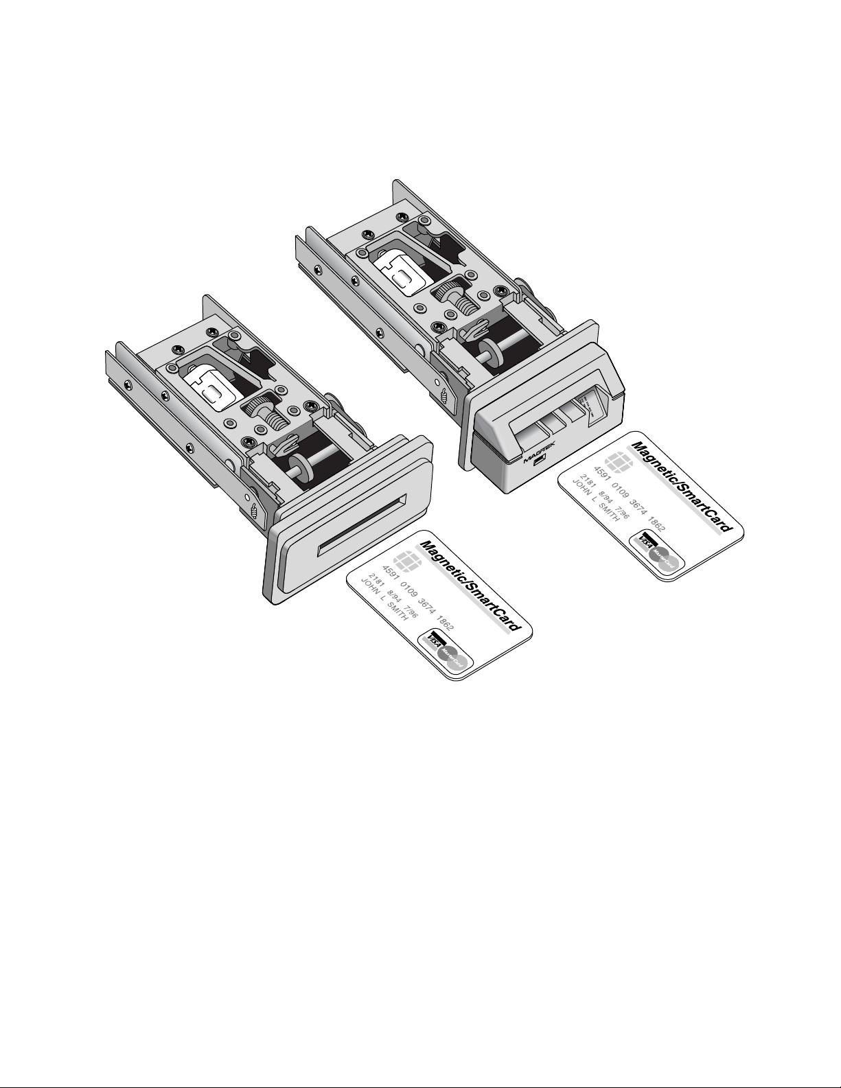
Figure 1-1. IntelliStripe 310 with “D” and “C” Beze
ls
ix
Page 10

Page 11

SECTION 1. FEATURES AND SPECIFICATIONS
he IntelliStrT
data format specifications: ISO (International Standards Organization), AAMVA, (American
Association of Motor Vehicle Administrators), CDL (California Drivers License). The
IntelliStripe 310 Reader can be used in environments such as self-service kiosks, vending
achines, and POS terminals. The IntelliStripe 310 is a 3-track Reader.m
he Reader communicates wiT
MCP protocol and command set, which has been developed by MagTek. Windows Drivers for
the MCP protocol are available and can support Win 95/98, NT, and Win 2000 operating
systems.
CONFIGURATIONS
The configurations of the IntelliStripe 310 are as follows:
STANDARD FEATURES
Standard features of the IntelliStripe 310 are as follows:
• Motorized transport
RS232 interface •
•
On board inte
command set
• Flash upgradable
• Supports all magnetic stripe 3-track combinations
Front Card Gate prevents coins, dust, moistu rom entering the unit – gate
• re, and debris, f
resists opening except when ISO-size card the unit
Power failu
• re card ejection system (requires optional external capacitor)
• Test LED
• External B
ipe 310, Motorized Reader, can read magnetic stripe cards and is compatible with
th a Host via an RS-232 serial interface, and uses a proprietary
Part Number Descrip
16050350 IntelliStripe 310, 3Trk, RS-232, with B Bezel, Stripe UP
16050351 IntelliStripe 310, 3Trk, RS-232, with C Bezel, Stripe down
16050352 IntelliStripe 310, 3Trk, RS-232, with D Bezel
16050356 IntelliStripe 310, 3Trk, RS-232, with A Bezel
lligence for transporting large blocks of data using a defined protocol and
ezel LED
tion
enters
1
Page 12

IntelliStripe 310 Motorized Reader
ACCESSORIES
Other part numbers that may be shipped with the unit are as follows:
RS232 / Power cable−6 foot IntelliStripe 310 host port to 9 pin D female RS232 and 2.5mm
•
power jack, part number 1605
1408
• Power Supply–Auto Ranging 100V-250V, regulated, 12VDC, 2.5mm plug, part number
64300080. Requires adapter to mate with power outlet; use Adapter/Power Cord part
number 71100001, for North American applications
Drivers, MC•
•
Demo Software, IntelliStripe P
30037435
P, 4-disk set, part number 30037437
icture Demo with MCP driver, 4-disk set, part number
• Communications Software, MCP3 Program, 4-disk set, part number 30037442 (must use
with 30037437)
RELATED DOCUMENTS
The following documents are relevant to this product:
99875163 MC
9875164 Communication Protocol, Driver Reference Manual
9
99875218 IntelliS
MOTORIZED TRANSPORT
The Reader has a command-driven ansport keeps the card from the
ser during a transaction but returns the card when the transaction is completed.
u
R
S-232 INTERFACE
T to the h The device uses 8 data bits, 1
he unit communicates ost through an RS-232 interface.
stop bit, even parity. The unit can automatically sync to baud rates 9600, 14400, 19200, 28800
3 rial
8400, and 57600. See MCP Driver Reference Manual, Part Number 99875164, MCP Se
T
ransport Protocol Reference Manual, Part Number 99875163, for more details.
P, Serial Transport Protocol, Reference Manual
tripe 310, Command Reference Manual
motorized transport. The tr
2
Page 13

Section 1. Features and Specifications
TEST LED
A D, designated D5 wil n when the unit is powered up. This indicates that the
Test LE l blink gree
u g This feature allows field
nit is in its standard operatin mode and is fully operational.
technicians to quickly verify that the device is op
erational.
EXTERNAL BEZEL LED
T e External bezel LED is show
h n in Section 2, Figure 2-2. The LED can be set to red, green or
off. See IntelliStripe 310 Comm
d tails. (Note: External LED o
e ptions are not supported with the “D” bezel.)
and Reference Manual, Part Number 99875218, for more
FLAS
H UPGRADABLE
T ystem
he unit's firmware is in-s Flash Upgradable. This allows the unit's firmware to be
upgraded in a field environmen
t.
M E
AGNETIC STRIPE READ R
The Reader can read up to three tracks of magnetic stripe card data. See IntelliStripe 310
C nual, P 2128, for more details.
ommand Reference Ma art Number 99875
P ARD EJ
OWER FAILURE C ECTION SYSTEM
The Reader has a power-failure ard-ejection system. This system will automatically eject a card
w ccurs. T ystem, an optional external capacitor needs to be
hen a power failure o
connected to ee Appendix A for more details.
the reader. S
c
o enable this s
F
RONT GATE
The Front Card Gate prevents c oisture, and debris, from entering the unit. The gate
r xcept when ISO e unit
esists opening e -size card enters th
oins, dust, m
Note
If the front-gate option is inst iStripe 310 Reader
will be incapable
card-ejection cyc
of reliably reading mag-stripe c
e. (Reliable mag-stripe readingl
possible during the card-insertion cycle). I
required during the card-ejection cycle, the
alled, the Intell
ards during the
will only be
f mag-stripe reading is
n the product must be
ordered without the front-gate option.
3
Page 14

IntelliStripe 310 Motorized Reader
CARD POSITION SENSORS
he reader contains three card position sensors: front card present sensor, middle card present
T
sensor, and rear card present sensor.
Front Card Present Sensor
An optical sensor that indicates whether a card is present at the front (insertion) end of the card
transport. See IntelliStripe 310 Command Reference Manual, Part Number 99875218, for more
details.
Middle Card Present Sensor
An optical sensor that indicates whether a card is present in the middle of the card transport. See
IntelliStripe 310 Command Reference Manual, Part Number 99875218, for more details.
Rear Card Present Sensor
An optical sensor that indicates whether a card is present at the rear (smart card contacts) end of
the card transport. See IntelliStripe 310 Command Reference Manual, Part Number 99875218,
for more details.
SPECIFICATIONS
Specifications for the Reader are listed in Table 1-1.
Table 1-1. Specifications
DATA FORMAT SPECIFICATIONS
Reader Configuration
Mag-Stripe Functions:
Track 1,2,3 only
Data Format Specifications*
ISO/AAMVA/CDL/JIS formats
ISO 7810, 7811, JIS x 6302 Type 2
* ISO (International Standards Organization), AAMVA, (American Association of Motor Vehicle
Administrators), CDL (California Drivers License), JIS (Japanese Industrial Standard)
OPERATIONAL
Card Speed: 10 IPS (25,4 cm/sec) typical
Recording Method: Two-frequency coherent phase (F2F)
MTBF: Electronics: 125,000 hours
Head: 1,000,000 passes (500,000 Insertion Cycles)
SC contacts: 1,000,000 passes
4
Page 15

Section 1. Features and Specifications
ELECTRICAL
Input Voltage:
Current:
Optional Auxiliary Power-Fail
Card-Eject Capacitor:
12.0 VDC ± 5%
1.5 A max
170 mA typical (with motor off)
Recommended capacitor value: 68000 μF rated at 16 volts.
MECHANICAL
Chassis Mounting Options: With "A" and "B" Bezel, screws mounted from under unit,
magstripe
up and to the left
With "A" and "C" Bezel, screws mounted from above unit, magstripe
down and to the right
Dimensions (Core Chassis)
Length (with "A" Bezel):
Width (with "A" Bezel):
Height (with "A" Bezel):
Length (with “B” or “C” Bezel):
Width (with “B” or “C” Bezel):
Height (with “B” or “C” Bezel):
Length (with “D” Bezel):
Width (with “D” Bezel)”:
Height (with “D” Bezel):
Cable Length (16051408):
Adapter Cable Length
(64300080):
Weight:
Reader with "A" Bezel:
"B" or "C" Bezel w/screws:
“D” Bezel w/screws:
Reader Cable:
AC Adapter Regulator with
Power Cord:
With "A" Bezel only, screws mounted from above or under unit.
With "D" Bezel, screws mounted from above or under unit.
5.60" (142.24 mm) (includes flex cable connector overhang)
3.26" (82.91 mm)
2.17" (55.12 mm)
6.54” (166.1 mm)
3.26" (82.91 mm)
2.17" (55.12 mm)
5.97” (151.6 mm)
4.00” (101.60 mm)
2.17" (55.12 mm)
6' ± 0.1' (1.83 m ±0.03 m)
6.25' (1.91 m)
14.95oz. (424.0 g.)
1.40 oz. (39.69 g.)
1.08 oz. (30.58 g.)
4.15 oz. (117.76 g.)
11.87 oz. (336.60 g.)
ENVIRONMENTAL
Temperature
Operating:
Storage:
Humidity
Operating:
Storage:
Altitude
Operating:
Storage:
o
F to 122 o F (0o C to 50o C)
32
o
F to 158 o F (-40o C to 70o C)
-40
5% to 95% noncondensing
5% to 95% noncondensing
0-10,000 ft. (0-3,048 m.)
0-50,000 ft. (0-15,240 m.)
5
Page 16

IntelliStripe 310 Motorized Reader
6
Page 17

SECTION 2. INSTALLATION
The installation of the IntelliStripe 310 Motorized Reader includes mechanical and electrical
connections.
MECHANICAL MOUNTING
The "A" Bezel is always shipped with the unit. The "B," "C," or “D” Bezels may also be shipped
with the unit, depending on requirements for card orientation. Figure 2-1 shows the
configurations for mounting and card orientation:
Figure 2-1. Bezel Options
7
Page 18

IntelliStripe 310 Motorized Reader
BEZELS
Dimensions and details of the three bezels are shown in Figure 2-2. The "A" Bezel will always
e shipped with the unit (“A” bezel dimensions are shown in Appendix B.) Also, the "B," "C,"
b
or “D” Bezel may be shipped with the unit. The user may also design a bezel from dime
in this sec
tion.
.300"
7.62 mm
2.17" 55.12 mm
.100"
1.771" 44.98 mm
2.54 mm
3.264" 82.91mm
3.064" 77.83 mm
.100"
2.54 mm
Bezel
Locator
Pin (2pl)
Threaded
Inserts (3pl)
LED
Opening
1.382"
35.10 mm
.430" 10.92 mm
.632"
16.05 mm
nsions
.976"
24.79 mm
.390"
9.91 mm
.300"
7.62 mm
2.17" 55.12 mm
.100"
1.771" 44.98 mm
2.54 mm
Front View
3.264" 82.91mm
3.064" 77.83 mm
Front View
4.00" 101.60 mm
3.745" 95.12 mm
2.50" 63.50 mm
.100"
2.54 mm
Threaded
Inserts (3pl)
.135"
3.43 mm
R .234"
5.944 mm
R .334"
8.484 mm
Bezel
Locator
Pin (2pl)
.240"
6.10 mm
2.764" 70.21 mm
Back View
LED
Opening
2.764" 70.21 mm
Back View
Bezel Locator
1.530"
38.86 mm
1.382"
35.10 mm
Pin (2pl)
.355" 9.02 mm
.150" 3.81 mm
.430" 10.92 mm
16.05 mm
.355" 9.02 mm
.150" 3.81 mm
Threaded
Inserts (3pl)
.632"
.976"
24.79 mm
.344"
8.74 mm
2.00" 50.80 mm
8
1.23"
31.24 mm
.390"
9.91 mm
.450"
Front View
11.43 mm
.410"
10.41 mm
Side View
2.764" 70.21 mm
Back View
1.382"
35.10 mm
Figure 2-2. Bezel Mounting Dimensions – B, C, and D Bezels
.632"
16.05 mm
9.02 mm
.675"
17.15 mm
.355"
.976"
24.79 mm
Page 19

Section 2. Installation
Figure 2-3 shows the position for mounting the IntelliStripe 310 with the “B” Bezel attached.
The mounting holes are shown in the bottom view. The "A" Bezel is attached to the unit by the
"A" Bezel Retaining screws also shown in the bottom view.
5.85"
148.59 mm
"A" Bezel
3.06"
77.72 mm
Retaining
Screw
Top View – "A" & "B" Bezels
5.60"
142.24 mm
1.95"
49.53 mm
#6 – 32 Thread
Mounting Holes –
.38" Internal
Thread Clearance
Figure 2-3. “B” Bezel Mounting – Top, Side, and Bottom Views
Side View
2.022"
51.36 mm
Bottom View – "A" Bezel Only
1.81"
45.97 mm
.102"
1.00"
25.48 mm
.365"
9.27 mm
1.233"
31.32 mm
.800"
20.32 mm
1.165"
29.59 mm
"A" Bezel
Retaining Screws
2.59 mm
9
Page 20

IntelliStripe 310 Motorized Reader
Figure 2-4 shows the position for mounting the IntelliStripe 310 with the “C” Bezel attached.
The mounting holes are shown in the top view. The "A" Bezel is attached to the unit by the "A"
Bezel Retaining screws also shown in the top view.
1.81"
45.97 mm
.365"
9.27 mm
.800"
20.32 mm
"C" Bezel
"A" Bezel
Retaining Screws
1.233"
31.32 mm
1.165"
29.59 mm
#6 – 32 Thread
Mounting Holes –
.38" Internal
Thread Clearance
2.022"
51.36 mm
T op Vie w
5.60"
142.24 mm
"C" Bezel
1.95"
49.53 mm
.102"
2.59 mm
3.06"
77.72 mm
5.60"
142.24 mm
"A" Bezel
Retaining
Screw
Bottom View
Side View
.98"
24.89 mm
"C" Bezel
Figure 2-4. “C” Bezel Mounting – Top, Side, and Bottom Views
10
Page 21

Section 2. Installation
Figure 2-5 shows the position for mounting the IntelliStripe 310 with the “D” Bezel attached.
The mounting holes are shown in the bottom view. The "A" Bezel is attached to the unit by the
"A" Bezel Retaining screws also shown in the bottom view. Because the “D” Bezel is
symmetrical, the unit may be mounted from the top or bottom, depending on the desired card
orientation. (Note that no LED is used with th
"A" Bezel
3.06"
77.72 mm
Retaining
e “D” Bezel configuration.)
5.60"
142.24 mm
Screw
T op Vie w
5.60"
142.24 mm
1.95"
49.53 mm
.088"
2.24 mm
Side View
2.022" 1.81"
51.36 mm 45.97 mm
#6 – 32 Thread
Mounting Holes –
.38" Internal
Thread Clearance "A" Bezel
Bottom View
.240"
6.10 mm
.410"
10.41 mm
.365"
9.27 mm
.800"
20.32 mm
Retaining Screws
1.233"
31.32 mm
1.165"
29.59 mm
Figure 2-5. “D” Bezel Mounting – Top, Side, and Bottom Views
11
Page 22

IntelliStripe 310 Motorized Reader
For “B” bezel configuration, the dimensions in Figure 2-6 are for the unit mounted from the
backside of the panel. These dimensions include the dimensions from the centerline of the card
ot to other areas for mounting the unit from the backside of the panel. Note the dimension
sl
from the top of the panel opening to the centerline. The same value in the "C" bezel is from the
bottom of the panel opening to the centerline
1.530"
20.32 mm
38.86 mm
.800"
.765"
19.43 mm
10.16 mm
ø.166" 4pl
4.22 mm
.400"
2.022"
51.36 mm
1.81"
45.97mm
R .125"
3.175 mm
4 pl
Front
Panel
.800"
20.32 mm
1.810"
45.97 mm
1.029"
26.14 mm
"B" Panel Opening
1.550"
39.37 mm
3.100"
78.74 mm
Figure 2-6. Panel Opening for Mounting "B" Bezel
It is not necessary to remove the Bezels when mounting the unit. The "B" Bezel protrudes from
the opening, and the "A" Bezel is positioned against the inside of the panel opening. The bracket
should retain the uni anel. t so the "A" Bezel is held firmly against the inside of the p
12
Page 23

Section 2. Installation
For “C” bezel configuration, the dimensions in Figure 2-7 are for the unit mounted from the
backside of the panel. These dimensions include the dimensions from the centerline of the
card
slot to other areas for mounting the unit from the backside of the panel. Note the dimension
from the bottom of the panel opening to the centerline. The same value in the "B" bezel is from
p of the panel opening to the centerline
the to
R .125"
3.175 mm
4 pl
Front
Panel
1.029"
26.14 mm
"C" Panel Opening
1.550"
39.37 mm
3.100"
78.74 mm
.800"
20.32 mm
1.810"
45.97 mm
Figure 2-7. Panel Opening for Mounting "C" Bezel
It is no
t necessary to remove the Bezels when mounting the unit. The "B" or "C" Bezel
protrudes from the opening, and the "A" Bezel is positioned against the inside of the panel
opening. The bracket should retain the unit so the "A" Bezel is held firmly against the inside of
the panel.
13
Page 24

IntelliStripe 310 Motorized Reader
For “D” bezel configuration, the two
om the backside of the panel. The openings are for mounting the outer or inner panel openings.
fr
sets of dimensions in Figure 2-8 are for units to be mounted
R .234"
5.944 mm
4 pl
Front
Panel
1.029"
26.14 mm
1.029"
26.14 mm
Front
Panel
"D" Outer Panel Opening
2.00"
50.80 mm
4.00"
101.60 mm
"D" Inner Panel Opening
1.00"
25.40 mm
R .334"
8.484 mm
4 pl
0.625"
15.875 mm
2.00"
50.80 mm
1.250"
31.75 mm
14
1.873"
47.56 mm
3.745"
95.12 mm
Figure 2-8. Panel Openings for Mounting "D" Bezel
Page 25

Section 2. Installation
Four #6-32 mounting screws, with 0.38 inch internal thread clearance, attach the bottom of the
IntelliStripe 310 to a fixed position as indicated in Figure 2-9. If the “B
ounting screws are inserted from under the IntelliStripe 310. If the “C” bezel is used, the
m
” bezel is used, the
IntelliStripe 310 is inverted, and the mounting screws are inserted from above the IntelliStripe
310.
Figure 2-9. Mounting Configurations
15
Page 26

IntelliStripe 310 Motorized Reader
)
(J4)
ELECTRICAL C
ONNECTIONS
Connectors and LEDs
Figure 2-10 shows the positions of
apacitor, and LEDs.
c
the connectors for the RS-232 Host I/O socket, power-fail
Test LED (D5
Pin 1
Host I/O 7-pin
Connector
Power-Fail
Capacitor
Connector
2-Pin (J7)
Pin 1
Jumper Block
8 - Factory Use
(J
Only)
Pin 1
Figure 2-10. Connector and LED locations
External Bezel L
(Three Lea
ds)
Red
Green
ED (D4)
16
Page 27

Section 2. Installation
Figure 2-11 shows the cable that connects the IntelliStripe 310 (7-Pin Co
nnector) to the host (9-
pin Connector), P/N 16051408. The standard length of the cable is 6'.
Locking
Tabs
Figure 2-11. Connector Locations, P/N 16051408
Table 2-1 lists the Connector Pin Numbers and Signal Names.
Table 2-1. Pin List for IntelliStripe 310 Connectors, P/N 16051408
Molex 7 Pin (51065-0700) DB-9 Female 2.5mm Power Jack
Pin Number Signal Name Pin Number Signal Name
1 TXD 2 RXD
2 +12V CENTER PIN +12V
3 PWR GND SHELL GND
4 RXD 3 TXD
5 RTS 8 CTS
6 CTS 7 RTS
7 SIGNAL GND 5 GND
6 DSR
4 DTR
17
Page 28

IntelliStripe 310 Motorized Reader
ower Supply
P
he Power Supply, P/N 64300080, 100V−240V regulated, 12VDC, with special 3.5mm plug is
T
own in Figure 2-12. The AC power cord , P/N 71100001, is for use in North America. Other
sh
sers must supply their own cord.
u
th American
Nor
100V–240V
Power Cord
Auto Range
Power Supply
12VDC Plug
GND
3 Prong
Connector
Figure 2-12. Power Supply
Power-Fail Capacitor Connector, 2-Pin
The Power-Fail Capacitor connector, J7, connects to an optional external capacitor that is used to
eject the card during a power failure. Pin 1 connects to the positive side of the capacitor and pin
2 connects to the negative side.
18
Page 29

APPENDIX A. OPTIONS
Options include a capacitor for the Power-Failure Car
POWER FAILURE CARD EJ
The externally m
ounted power-fail capacitor is shown in Figure A-1.
ECT SYSTEM
d-Eject System.
Figure A-1. Card Eject Capacitor
The power-failure card-eject system ejects a card during a power failure. Card ejection is
triggered when the power to the reader fails. An external backup capacitor is required for this
option to function. This capacitor can be connected to the reader through a header on the board.
In case of power failure, the capacitor automatically ejects the card. The user must determine the
wire length required for their specific application. The recommended capacitor value is 68000uF
rated at 16 volts.
19
Page 30

IntelliStripe 310 RS232 Motorized Reader
20
Page 31

Not Both
3BAPPENDIX B. BEZEL A DIMENSIONS
The “A” Bezel dimensions are shown in Figure B-1.
3.264" 82.91mm
2.764" 70.21mm
.250"
6.35mm
1.47"
37.34mm
2.17" 55.12mm
1.086"
1.894" 48.11mm
27.58mm
(2 pl)
*
"B" Or "C"
Bezel
Retaining
Holes (6pl)
*
Bezel
Locator
Holes (2pl)
.35"
8.89mm
.150"
3.81mm
.326"
8.28mm
LED Is In
*
One Place
Or The Other,
Figure B-1. Bezel “A” Dimensions
21
Page 32

IntelliStripe 310 RS232 Motorized Reader
22
 Loading...