

Page 1

HALF CARD PORT POWERED
INSERTION READER
TECHNICAL REFERENCE MANUAL
Manual Part Number 99875234-7
FEBRUARY 2007
REGISTERED TO ISO 9001:2000
1710 Apollo Court
Seal Beach, CA 90740
Phone: (562) 546-6400
FAX: (562) 546-6301
Technical Support: (651) 415-6800
www.magtek.com
Page 2

Copyright© 2002-2007
MagTek®, Inc.
Printed in the United States of America
Information in this document is subject to change without notice. No part of this document may
be reproduced or transmitted in any form or by any means, electronic or mechanical, for any
purpose, without the express written permission of MagTek, Inc.
MagTek is a registered trademark of MagTek, Inc.
REVISIONS
Rev Number Date Notes
1 21 Jun 02 Initial Release
2 09 Sep 02 Editorial comments throughout. Sec 1: Buffered Mode, clarified data
and error status, clarified output when sensor is blocked or card
withdrawn, Related Documents, added source of ISO specs, Specs:
added cmps for card speed, added 6’ cable, corrected storage temp
to 176 degrees, modified Related Documents to qualify characters in
Tk 1 and Tk 2, corrected Fig 1-2 side view dimension. Sec 2:
corrected Table 2-1 and added Molex connectors, corrected Table 22 by adding P designations. Sec 3: Table 3-2: added red and green
LED status and to note “LED controlled by Host”, added Watchdog
LED paragraph, added optional statement to card insertion block,
clarified Tables 3-3 and 3-4.
3 13 Jun 03 Front Matter: added ISO line to logo, changed Tech Support phone
number, added new warranty statement.
4 26 Jun 03 Sec 1: added part number to Table 1-1; Specifications: changed
operating temperature to before (32
shipping date.
5 30 Aug 04 Sec 3, Table 3-2: changed To Set Option L(0x52) to L(0x4C); Table
3-3: added Card Inserted line and Card Removed line at the end of
the table, added “data buffer is cleared” to “Sends card data…” line.
6 15 Nov 04 Sec 1, Table 1-1: Added P/N 21066020, 215232 Insertion Reader
TK1,2 1Head Right, Half Card Port Powered, Black.
7 9 Feb 07 Added new model 21066000; updated throughout to include printed
circuit board 21067505; added ability to configure the communication
parameters; added configuration commands
o
F) and after (-4 oF) 1 Nov 03
ii
Page 3

Limited Warranty
MagTek, Inc. warrants that the Product described in this document is free of defects in materials and
workmanship for a period of one year from the date of purchase where the date of purchase is defined as
the date of shipment from MagTek. During this warranty period, MagTek shall, at their option, repair or
replace without charge for either parts or labor, any failure, malfunction, defect or nonconformity which
prevents the product from performing in accordance with MagTek’s published technical specifications
and manuals.
This warranty does not apply to wear of the magnetic read head. This warranty shall not apply if the
product is modified, tampered with, or subject to abnormal working conditions. This warranty does not
apply when the malfunction results from the use of the Product in conjunction with ancillary or peripheral
equipment where it is determined by MagTek that there is no fault in the Product itself.
Notification by the Customer to MagTek of any condition described above should be directed to the
Customer’s MagTek Sales Representative or to MagTek’s Help Desk at (651) 415-6800. If the Product is
to be returned from the Customer to MagTek, a returned material authorization (RMA) will be issued by
MagTek. The Customer shall be responsible for shipping charges to MagTek, (1710 Apollo Court, Seal
Beach, CA 90740). MagTek shall be responsible for shipping charges back to the Customer.
Repair or replacement as provided under this warranty is the exclusive remedy. This warranty is in lieu
of all other warranties, express or implied.
iii
Page 4

FCC WARNING STATEMENT
This equipment has been tested and found to comply with the limits for Class B digital device, pursuant to
Part 15 of FCC Rules. These limits are designed to provide reasonable protection against harmful
interference when the equipment is operated in a residential environment. This equipment generates,
uses, and can radiate radio frequency energy and, if not installed and used in accordance with the
instruction manual, may cause harmful interference to radio communications. However, there is no
guarantee that interference will not occur in a particular installation.
FCC COMPLIANCE STATEMENT
This device complies with Part 15 of the FCC Rules. Operation of this device is subject to the following
two conditions: (1) This device may not cause harmful interference. And (2) This device must accept any
interference received, including interference that may cause undesired operation.
CANADIAN DOC STATEMENT
This digital apparatus does not exceed the Class B limits for radio noise for digital apparatus set out in the
Radio Interference Regulations of the Canadian Department of Communications.
Le présent appareil numérique n’émet pas de bruits radioélectriques dépassant les limites applicables
aux appareils numériques de las classe B prescrites dans le Réglement sur le brouillage radioélectrique
édicté par les ministère des Communications du Canada.
CE STANDARDS
Testing for compliance to CE requirements was performed by an independent laboratory. The unit under
test was found compliant to Class B.
UL/CUL
This product is recognized per Underwriter Laboratories and Canadian Underwriter Laboratories 1950.
iv
Page 5

TABLE OF CONTENTS
SECTION 1. FEATURES AND SPECIFICATIONS.....................................................................................1
FEATURES...............................................................................................................................................1
CONFIGURATIONS.................................................................................................................................2
MODES OF OPERATION ........................................................................................................................3
Unbuffered Mode..................................................................................................................................3
Buffered Mode...................................................................................................................................... 3
RELATED DOCUMENTS.........................................................................................................................4
SPECIFICATIONS....................................................................................................................................4
DIMENSIONS...........................................................................................................................................7
SECTION 2. INSTALLATION...................................................................................................................... 9
CONNECTORS........................................................................................................................................9
PC Connector.......................................................................................................................................9
MOUNTING............................................................................................................................................10
Orientation..........................................................................................................................................11
SECTION 3. COMMANDS, FORMATS, TIMING......................................................................................13
HOST TO READER COMMANDS.........................................................................................................13
WATCHDOG LED ..................................................................................................................................14
READER TO HOST FORMATS.............................................................................................................15
TIMING FOR ID SIGN-ON AND TRANSMISSION BURSTS.................................................................17
TRANSMISSIONS EXAMPLES .............................................................................................................18
PROGRAM MODE .................................................................................................................................20
Sending Program Mode Commands..................................................................................................20
PROGRAM MODE COMMAND SET.....................................................................................................21
Exit Program Mode.............................................................................................................................21
Reset Device ...................................................................................................................................... 21
Version Request.................................................................................................................................21
Upload Command...............................................................................................................................21
Configuration Commands................................................................................................................... 22
Switch A..............................................................................................................................................23
Switch B..............................................................................................................................................24
Switch C..............................................................................................................................................25
Sentinel Definitions.............................................................................................................................26
v
Page 6

FIGURES and TABLES
Figure 1-1. Half Card Port Powered Insertion Reader................................................................................vii
Table 1-1. Configuration...............................................................................................................................2
Table 1-2. Specifications..............................................................................................................................5
Figure 1-2. Half Card Reader Dimensions...................................................................................................7
Table 2-1. J1 Connector - RS232................................................................................................................9
Table 2-2. P2 Connector and Cable ............................................................................................................9
Figure 2-1. Reader Layout - Top................................................................................................................10
Figure 2-2. Reader Layout -Bottom ...........................................................................................................11
Table 3-1. Commands and Responses .....................................................................................................13
Table 3-2. Options and Reader Responses...............................................................................................14
Figure 3-1. Timing For ID Sign-on and Transmission Bursts.....................................................................17
Table 3-3. Transmission Data Examples Not in Buffered Mode................................................................ 18
Table 3-4. Transmission Data Examples in Buffered Mode With STX and ETX Included........................19
Table 3-5. Switch A....................................................................................................................................23
Table 3-6. Switch B....................................................................................................................................24
Table 3-7. Switch C....................................................................................................................................25
Table 3-8. Start and End Sentinels............................................................................................................26
vi
Page 7
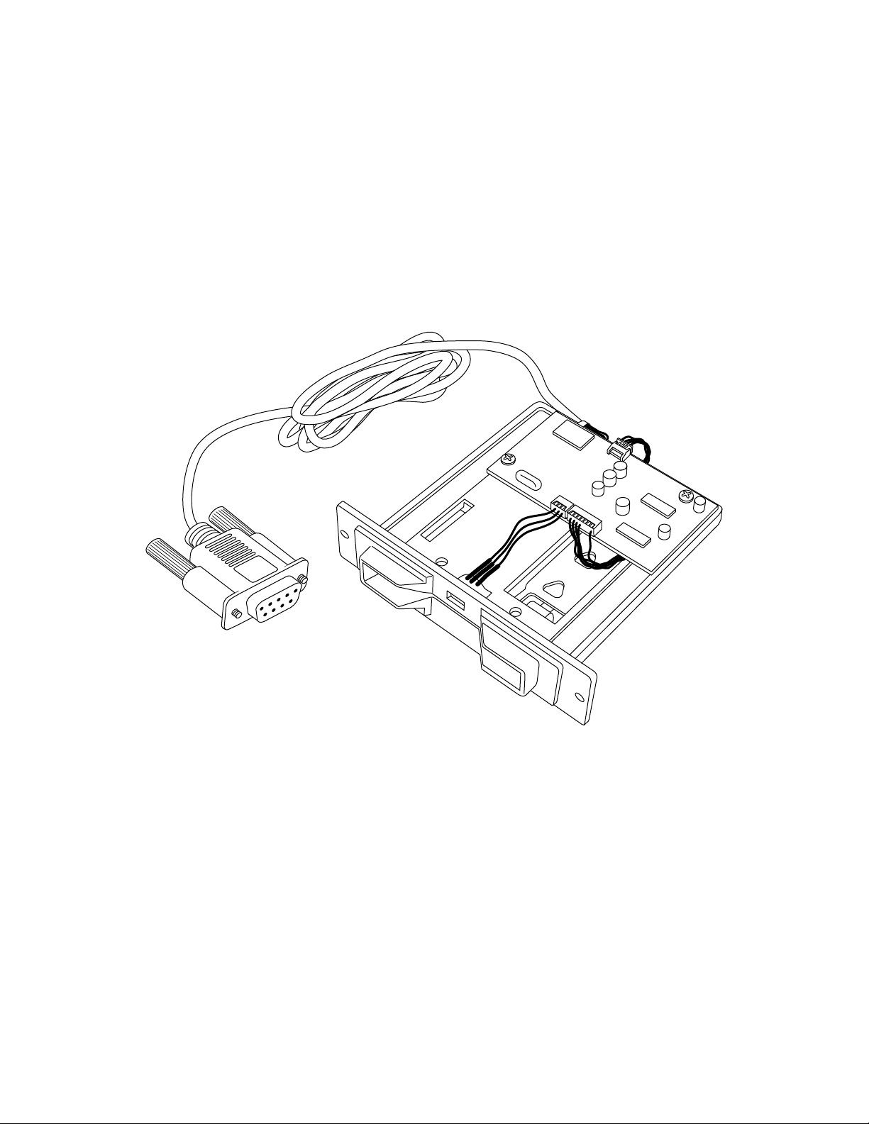
Figure 1-1. Half Card Port Powered Insertion Reader
vii
Page 8

Page 9

SECTION 1. FEATURES AND SPECIFICATIONS
The Half Card Port Powered Insertion Reader is a single-head, dual-track configuration (Tracks
1 and 2). The magnetic stripe is down and to the right as viewed from the front of the Reader.
The single head configuration can read the card on insertion and removal.
FEATURES
Features of the Reader are as follows:
• Port Powered RS-232 Interface – No power pack required, powered from PC port with
computers having an RS-232 interface
• Card Present Opto-sensor – Detects if card is fully inserted in Reader
• Dual-Color LED – Red/Green colors provide visual cues to the card holder
• Watchdog LED – Provides visual cues to service personnel to verify Reader electronics are
operational
• Open Chassis design – Provides superior debris clearing capability
• Isolated PCB – Isolates electronics from debris and liquids
• Beam-mounted Read-head – Provides superior tracking of bowed or warped cards
• Mag-Stripe reading during insertion and removal of card – For reliable card reading
• AGC F2F ASIC – Provides improved ability to read cards (Automatic Gain Control, Two
Phase Frequency, and Application Specific Integrated Circuit)
• Command Selectable Buffered or Unbuffered Modes – Provides greater versatility of
operating modes
• Command Selectable Framing Characters – Provides selection of STX, ETX, ESC, and CR.
• ASCII Message Format at 9600, also 19.2k, 38.4k, 57.6k, or 115.2k bps for new reader (33%
duty cycle)
1
Page 10

Half Card Port Powered Insertion Reader
CONFIGURATIONS
Table 1-1 lists the part number, single or dual head, head positions, tracks, and cable type.
Note
Additional features have been incorporated into the new version of
the Half Card Insert Reader (generally available after December
2006). In the new version, the firmware part number will be
reported as 21088842. This new reader was designed to be a drop
in replacement for the old reader. However, there are some slight
behavior differences mentioned throughout this manual. This new
reader also added a number of features that are mentioned
throughout this manual. The part number of the readers did not
change for the new readers, however the revisions did change.
The enhancements included in this new version are identified
within this document with the word “new”.
Table 1-1. Configuration
Part Number Heads Head Position* Track Bezel Cable Type
21066000 Single Head Down/Right 1-2 Black No Cable
21066008 Single Head Down/Right 1-2 White 6’ Cable
21066019 Single Head Down/Right 1-2 White No Cable
21066020 Single Head Down/Right 1-2 Black 6’ Cable
21166021 Single Head Down/Right 1-2 White No electronics,
no cable
* The magnetic stripe is inserted in the same orientation as the head position; for example,
head down/right means magnetic stripe down or to the right.
2
Page 11

Section 1. Features and Specifications
MODES OF OPERATION
The Reader can operate in either unbuffered or buffered mode. The modes are described below.
The note that follows applies to both modes.
Note
The insertion and removal of the card must be done in a
continuous motion. If not, the Reader may not read the encoded
data properly. In that case, the Reader responds by either
transmitting the ASCII character “E” representing an error, or by
not transmitting any character, which indicates that the Reader
has not detected data and the card was not completely inserted.
Unbuffered Mode
When a card is inserted and removed, a read attempt is made during both insertion and removal.
If the read is successful, data (including the two sentinel characters) is sent to the PC. The data
is transmitted immediately after removing the card and not re tained in the Reader.
When operating in the unbuffered mode, the Reader does not need to receive commands from the
host in order to transmit data or status characters, and data, if available; however, the Reader
does respond to an “Inquiry Command” by sending status characters. The inquiry command that
requests the transmission is the ESCAPE (ESC) character followed by “I” (0x49).
In the unbuffered mode, data can be retrieved from the card after the card has been inserted and
while it is blocking the rear sensor. Issuing an “Inquiry Command” (see Section 3) will retrieve
data from the card.
Buffered Mode
When a card is inserted and removed, a read attempt is made during both insertion and removal.
Upon removal of the card if the read is successful, data (including the two sentinel characters) is
stored in a memory buffer on the Reader and is not transmitted until the Reader receives an
“Inquiry Command” from the host. This command is the ESCAPE character followed by “I”.
The data or error status is available when the back sensor is blocked, however the Release
Command will not clear the buffer. The Reader cannot read another card until the buffer is
cleared. To clear the buffer, the Host must transmit the ESCAPE character followed by “R”.
The unit will always output a 1 and enabled optional characters when the back sensor is first
blocked. It will output a 0 and enabled optional characters when the card has been withdrawn.
See Section 3, Table 3-4 for detailed examples.
3
Page 12

Half Card Port Powered Insertion Reader
RELATED DOCUMENTS
MagTek 99875125 The MagTek Device Drivers for Windows, Part Number
30037385, may be used with the Port Powered Insertion Reader.
The title of the manual is MagTek Device Drivers For Windows
Programming Reference Manual.
The Port Powered Insertion Reader will read cards that meet the standards defined by ISO
(International Standards Organization) with the exception that track 1 can only contain up to 51
characters and track 2 up to 25 characters:
ISO 7811 Identification Cards - Mag-stripe Cards, Tracks 1-3
ISO 7810 Identification Cards - Physical Specifications (ID-1 Cards)
Available from ANSI Phone 212-642-4900, www.ansi.org
SPECIFICATIONS
The Specifications are listed in Table 1-2.
4
Page 13

Section 1. Features and Specifications
Table 1-2. Specifications
OPERATING
Reference Standards ISO7810 and 7811;
51 Characters on Track 1, 25 on Track 2
Power Input From RS-232 Interface or Auxiliary Power Input (some units)
Interface Signal RS-232 compatible
Message Format ASCII
Track Card Speed 3 to 50 IPS (7,6 to 127 cm/sec)
Head Life 500,000 Insertion Cycles (1,000,000 head passes)
ELECTRICAL
DTR Voltage (Input)
V
DTR
Transmit Data (TXD) +/-5 VDC minimum +/-(V
Receive Data (RXD) +/-15 VDC op erating
Communication
(bursts of 5 ms transmit with
10 ms idle between bursts)
DTR Current
Or Auxiliary Supply Current
(Positive supply to unit)
Power On 12 mA Max (and practically
Transmitting 11 mA typical, 5 ms duration See above.
Quiescent 6 mA typical, continuous See above.
RXD Current Within RS-232 specified limits
Output Cable Not Specified See note “*” below.
Dimensions
Length
Width
Height
Weight 4.1 oz (115 g) including 6’ cable
Printed Circuit Assembly
21067502 (discontinued)
+5 to +15 VDC operating
+16 VDC absolute maximum
-25 VDC absolute maximum
Printed Circuit Assembly
21067505 (new unit)
+5 to +15 VDC operating
+/-20 VDC absolute maximum
– 0.4 V) VDC
DTR
minimum
+/-15 VDC operating
+/-25 VDC absolute maximum
Transfer Rate: 9600 bps, 33%
duty cycle; 8 data bits, no
parity, 1 stop bit
+/-20 VDC absolute maximum
Transfer Rate: Selectable
9600, 19.2k, 38.4k, 57.6k,
115.2k bps, all at 33% duty
cycle; 8 data bits, no parity, 1
stop bit or configurable
See below
* 2.7 mA minimum required
under all operating conditions
with cable capacitance limited
to 1000pF (and practically
unlimited inrush current)
See above.
unlimited inrush current)
Average current approximates
(does not function as a
negative supply to unit)
that of a normal RS-232 load.
(Negative supply to unit)
MECHANICAL
3.86 in (98.0 mm) – Allow 0.30 in (7.6 mm) for cable thickness
and tie wrap at the rear of the unit
4.00 in (101.6 mm)
1.00 in (25.4 mm)
5
Page 14

Half Card Port Powered Insertion Reader
ENVIRONMENTAL
Temperature
Operating
Storage
Humidity
Operating
Storage
Printed Circuit Assembly
21067502 (discontinued)
o
F to 158oF (-20oC to 70oC)
4
o
F to 176oF (-40oC to 80oC)
-40
10% to 90% noncondensing
10% to 90% noncondensing
Printed Circuit Assembly
21067505 (new unit)
-40°F to 158°F (-40°C to 70°C)
o
F to 176oF (-40oC to 80oC)
-40
* The 2.7 mA figure is for continuous data transmission at 33% duty cycle while
reading a card. Typical capacitance from TXD is about 1000 pF for our standard 2 m
cable. Minimum DTR current ‘IT’ required for continuous transmission at 33% duty
cycle, while reading a card, with cable capacitance ‘C’ and arbitrary baud rate is
approximately:
IT = (2.5 mA) + (10 V) * 33% *(baud rate in Hz) / 2 * C.
Maximum transmission burst time ‘T’ at 33% duty cycle for RS-232 compatibility is
approximately:
T = (64 μF) * (5 V - 3.4 V) / (IT - IS), where IS is the current supplied by the DTR
line (T is unlimited for IS > IT)
A note about “port-powered” readers: These readers operate off some combination of otherwise
unused RS-232 lines, DTR and TXD from the host in this case. Per the RS-232 specification,
these lines are only required to drive a 3 kΩ load at +/-5 V. This is a current of merely 5 V / 3
kΩ=1.67 mA per line. All “port-powered” readers fundamentally require more current than 1.67
mA (consider that at least 1.67 mA must be supplied to a 3 kΩ load, and some extra current is
needed for the circuit that does so). Thus these readers are not technically guaranteed to work
unless multiple unused lines are used for power and/or some duty cycle limit is imposed on
transmitting while employing an energy storage device (a capacitor). In practice, however most
ports can easily supply the 2.7 mA at +5 V required by this new reader on DTR and the nearspecification average TXD (from host) current at -5 V. This new reader is MagTek’s lowest
current “port-powered” reader to date. Strictly speaking, some RS-232 ports may not supply the
required current, and this is the reason for including a current consumption specification for a
“port-powered” device. The current drive capability of an RS-232 port is not typically specified,
so experimentation may be required in a particular application. If more current is needed for the
positive supply, RTS may be paralleled with DTR (both host-referenced) in the cabling to the
unit. If this is done, the host must of course hold RTS high.
6
Page 15

Section 1. Features and Specifications
DIMENSIONS
The dimensions and tolerances for the Reader are shown in Figure 1-2.
1.000
± .015
0.75
± .01
3.740 ± .01
3.247 ± .015
2.135 +.003 –.001
4.000 ± .015
R .06 ±.01
(4 places)
Ø .140 ±.01
(2 places)
3.856 ± .015
.300
±.015
.75
±.015
.230
Ref.
4.000 ± .015
Figure 1-2. Half Card Reader Dimensions
7
Page 16

Half Card Port Powered Insertion Reader
8
Page 17

SECTION 2. INSTALLATION
This section describes Connectors, cabling information, mounting, and card orientation.
CONNECTORS
The connector pin list is shown in Table 2-1. The mating connector manufactured by Molex is
51021-0400. The Molex Terminal is 50058-8000.
Table 2-1. J1 Connector - RS232
PIN NUMBER SIGNAL (HOST AS REFERENCE)
J1-1 RXD (To PC)
J1-2 TXD (From PC)
J1-3 DTR (From PC)
J1-4 GND
All pins must be connected as shown.
PC Connector
The serial cable is shown in Figure 2-1. One end connects to J1 and the other end is a DE-9
female. The pin list for the cable connectors is shown in Table 2-2.
Table 2-2. P2 Connector and Cable
P2 SIGNAL COLOR P1
1 NC* -- -2 RXD YELLOW 1
3 TXD GREEN 2
4 DTR ORANGE 3
5 GND BROWN 4
6-9 NC* -- -*NC = No connection
All pins (except NC) must be connected as shown.
9
Page 18

Half Card Port Powered Insertion Reader
MOUNTING
Figure 2-1 shows the board layout orientation as viewed from the top. The Reader is attached to
the customer plate with two mounting screws. There are three levels on the front face: the
bracket with the mounting holes; the beveled race above the mounting bracket; and the card
guide brackets. The unit is mounted to the inside of the user’s surface. The mounting bracket is
not seen by the customer, and the beveled race and area above it and the card guide brackets are
visible to the customer.
Dimensions and tolerances are shown in Section 1, Figure 1-2.
Tie Wrap
Pin 1
J1
PCB
J4
Mounting
Hole
Pin 1
Pin 1
J3
PC Connector
Pin 5
Pin 9
Card With
Stripe Down
Pin 6
Pin 1
LED
Card Slot
Mounting
Hole
Read Head
Figure 2-1. Reader Layout - Top
For the LED shown in the illustration refer to Section 3, Table 3-2, for setting the color options.
10
Page 19

Section 2. Installation
Orientation
The Reader is mounted as oriented in Figure 2-1, or it may be rotated 90o counterclockwise from
that orientation. In the latter position, debris and foreign objects can clear the unit without
damaging head or card stop areas, shown in Figure 2-2.
Card Stop
Card-Seated Sensor
Beam-Mounted
Read Head
Figure 2-2. Reader Layout -Bottom
The Reader should be mounted only in the two orientations describe above, so that the magnetic
stripe is facing down and to the right or up and to the right
11
Page 20

Half Card Port Powered Insertion Reader
12
Page 21

SECTION 3. COMMANDS, FORMATS, TIMING
This section includes commands, message formats, and transmission timing.
The MagTek Device Drivers for Windows, part number 30037385, may be used with the Half
Card, Port Powered Insertion Reader. When these drivers are used, refer to MagTek Device
Driver for Windows, Programming Reference Manual, Part Number 99875125.
When power is applied, the Reader transmits a sign-on ID message. About 150 (500 for the new
reader) milliseconds after DTR is applied, the Reader sends the part number of the firmware in
the following form: 21088828A01 (21088842A01 for the new reader). The first 8 characters
indicate the firmware number; the letter is the revision, which is followed by a revision sublevel
of 01 to 99.
Since the input voltage is supplied by a relatively low source of power, the Reader depends on its
input capacitor to maintain proper charge during all operations. In order to reduce the drain on
this internal power source during data transmission, the output data is transmitted in 5 to 6
millisecond bursts with a 10-millisecond gap between bursts1 to allow the capacitor to recharge.
The PC software should be able to tolerate this 10-millisecond space between characters.
HOST TO READER COMMANDS
All commands transmitted from the Host to the Reader must be preceded by the ASCII
“ESCAPE” character (0x1B). These command messages may contain other framing characters
that are ignored by the Reader. Table 3-1 describes the commands and responses. Table 3-2 lists
setting and clearing options and the responses.
Table 3-1. Commands and Responses
HOST COMMANDS READER RESPONSES
COMMAND PREFIX USE EITHER CHARACTER
<ESC> (0X1B) I (0x49) + (0x2B) Inquiry command causes the Reader to
transmit data, error, or status message.
This command works in both the
buffered and unbuffered modes.
<ESC> (0X1B) R (0x52) - (0x2D) Release command causes the Reader
to clear its memory buffer of any data
present. This command works only in
the Buffered mode.
The Inquiry command (I/+) will transmit data after the card has been inserted even if not in the
buffered mode. This allows a card to remain in the slot during the transaction. If not in the
buffered mode, the card data will also be transmitted when the card is removed. (Refer to Tables
3-3 and 3-4 for examples.)
1
For the 21067505 printed circuit assembly, the transmission is strictly in 5 ms bursts with 10 ms between.
13
Page 22

Half Card Port Powered Insertion Reader
Table 3-2. Options and Reader Responses
COMMAND
PREFIX
<ESC> (0x1B) S (0x53) s (0x73) Send STX
<ESC> (0x1B) E (0x45) e (0x65) Send ETX
<ESC> (0x1B) C (0x43) c (0x63) Send CR
<ESC> (0x1B) P (0x50) p (0x70) Send ESC
<ESC> (0x1B) B (0x42) b (0x62) Buffered Mode
<ESC> (0x1B) G (0x47) - Green LED On, Red LED off
<ESC> (0x1B) L (0x4C) - Red LED On, Green LED off
<ESC> (0x1B) O (0x4F) Both LEDs Off (default)
<ESC> (0x1B) Q (0x51) q (0x71) Quiet Mode; Buffered Mode (reader
<ESC> (0x1B) V (0x56)
<ESC> (0x1B) X (0x58)
TO SET OPTION TO CLEAR OPTION
(DEFAULT)
- Version request. Same as the
New reader only
See the exit program
New reader only
mode command in the
program mode
command set section.
READER FUNCTION
does not send status)
program mode version request
command except the reader does
not send an ACK character in the
response.
Enter program mode. See program
mode section for a full description.
The device will only respond to the
program mode command set when
in program mode.
Note
If DTR is dropped and restored, the setup options are returned to
the default state. Some default states can be modified by the
program mode command set in the new reader. The LED is
controlled by the Host.
WATCHDOG LED
A watchdog LED provides a visual clue to service personnel that the Reader electronics are
operational. This LED is located on the PCB and is designated D1. If power is applied and the
CPU is in its normal idle loop, the LED will continually blink green, on for approximately one
second, off for one second. If an encoded card is withdrawn from the Reader at the beginning of
the on cycle, the LED should give an extra short blink. For the new reader, the watchdog LED
remains off when the dual color LED is on.
14
Page 23

Section 3. Commands, Formats, Timing
READER TO HOST FORMATS
The following diagram represents the format of the data transmitted to the Host:
STX ESC % Track 1 Data ? ; Track 2 Data ? Sensor CR ETX
Optional
Where optional characters
STX (0x02) = Start of text character
ESC (0x1B) = Escape character
CR (0x0D) = Carriage return character
ETX (0x03) = End of Text
are used to frame data.
These sentinel characters can be changed in the new reader by using the program mode
command set.
% = Start Sentinel Track 1
; = Start Sentinel Track 2
? = End Sentinel
The LRC character is not transmitted.
Track data may be represented as follows:
SS Track Data ES Card Sensor Status
Where
SS = Start Sentinel: "%" for Track 1; ";" for Track 2
Data = Track Data in track order that is, Track 1 then Track 2
ES = End Sentinel: "?"
Sensor = "0" no card in reader
"1" card present in reader (rear sensor blocked)
If there is an error in one of the tracks, the "Track Data" field will be replaced with "E" (0x45).
15
Page 24

Half Card Port Powered Insertion Reader
An example of a card insertion or removal is as follows when the Back Sensor is first blocked by
the card:
STX ESC 1 CR ETX
Optional
Where 1 indicates Sensor blocked; 0 indicates the sensor became unblocked.
The following is an example of a good read on withdrawal of a card:
STX ESC % Track 1 Data ? ; Track 2 Data ? 0 CR ETX
Optional
Where 0 indicates the sensor unblocked.
The following is an example of a bad read on Track 1 and a good read on Track 2 on withdrawal
of a card:
STX ESC % E ? ; Track 2 Data ? 0 CR ETX
Optional
Where
E (0x45) = Error
Track 2 Data = Good read Track 2 Data
0 = Sensor unblocked
16
Page 25

Section 3. Commands, Formats, Timing
TIMING FOR ID SIGN-ON AND TRANSMISSION BURSTS
Timing for the ID Sign-on and transmission bursts (5 ms with 10 ms between bursts) is shown in
Figure 3-1.
MCU*
150 ms (500 ms for the new reader)
Sign-on ID
Transmission
Burst
5 ms
10 ms
NOT TO SCALE
* Up to 1.5 seconds are required from DTR rising until the MCU comes out of reset.
Figure 3-1. Timing For ID Sign-on and Transmission Bursts.
The firmware controls the operation of ID Sign-on and Transmission bursts. The ID sign-on is
21088828A04 (21088842A01 in the new reader)
Where:
21088828 is the firmware part number,
A is the alpha revision, and
04 is the number sub-revision.
17
Page 26

Half Card Port Powered Insertion Reader
TRANSMISSIONS EXAMPLES
Table 3-3 shows transmission examples not in the buffered mode:
Table 3-3. Transmission Data Examples Not in Buffered Mode
Action Port Powered Insert Reader Data PC Data
Card Inserted 1 (0x31)
PC Sends Inquiry (if the application needs
data before card removed)
Bad read on insert so reader sends error
plus card status
Card removed %<track 1 data>?;<track 2 data>?0
Card Inserted 1 (0x31)
PC Sends Inquiry (if the application needs
data before card removed)
Sends card data plus card status; data
buffer is cleared
Card removed (card data is always
transmitted when the card is removed if not
in buffered mode)
Card Inserted 1 (0x31)
Card removed (card data is always
transmitted when the card is removed if not
in buffered mode)
<ESC> I
(0x1B, 0x49)
%E?;E?1 (0x25, 0x45, 0x3F, 0x3B,
0x45, 0x3F, 0x31)
<ESC> I
%<track 1 data>?;<track 2 data>?1
%<track 1 data>?;<track 2 data>?0
%<track 1 data>?;<track 2 data>?0
(0x1B, 0x49)
18
Page 27

Section 3. Commands, Formats, Timing
Table 3-4 shows transmission examples in the buffered mode with STX and ETX included:
Table 3-4. Transmission Data Examples in Buffered Mode With STX and ETX Included
Action Port Powered Insert Reader Data PC Data
PC Sets Buffered Mode <ESC>B
(0x1B, 0x42)
PC Sets STX <ESC>S
(0x1B, 0x53)
PC Sets ETX <ESC>E
(0x1B, 0x45)
Card Inserted <STX>1<ETX> (0x02, 0x31, 0x03)
PC Sends Inquiry <ESC>I
(0x1B, 0x49)
If bad read on insert, reader sends error
status
If good read on insert, sends card data <STX>%<track 1 data>?;<track 2
Card removed <STX>0<ETX> (0x02, 0x30, 0x03)
PC Sends Inquiry <ESC>I
Sends card data <STX>%<track 1 data>?;<track 2
PC Sends Inquiry <ESC>I
Sends card data (data remains in buffer
until a release command has been
received)
Buffer cleared (released) <ESC>R
PC Sends Inquiry <ESC>I
Sends status <STX>0<ETX> (0x02, 0x30, 0x03)
<STX>%E?;E?1<ETX>(0x02,0x25,
0x45,0x3F,0x3D,0x45,0x3F,0x31,0x03)
data>?1<ETX>
data>?0<ETX>
<STX>%<track 1 data>?;<trac k 2
data>?0<ETX>
(0x1B, 0x49)
(0x1B, 0x49)
(0x1B, 0x52)
(0x1B, 0x49)
19
Page 28

Half Card Port Powered Insertion Reader
PROGRAM MODE
The new reader has a number of non-volatile properties. Once these properties are changed and
saved in non-volatile memory, the changes will take affect after a power cycle or reset. These
properties are usually only modified once prior to installing the device. These properties can
only be modified when in program mode. See the enter program mode command in the regular
command set for a description of how to enter program mode. Once in program mode, the
reader will only respond to the program mode command set until the device is power cycled,
reset or the exit program mode command is received. This section describes the program mode
commands set.
Sending Program Mode Commands
The Reader will operate from 2400 to 115200 bps but each command sent to the Reader must
match the communication parameters of the Reader. The default communication parameters are
9600 bps with 8 bits, no parity and 1 stop bit (8N1). If the Reader fails to respond after a
command has been transmitted, the application should modify the transmission parameters until
a response is received.
Commands, as described below, must be preceded by an Escape (<ESC> – 0x1B) character and
be terminated by a Carriage Return (<CR> – 0x0D). All commands are case sensitive—that is,
they must all use upper case characters.
After a valid command has been received, the Reader will respond with an Acknowledge
(<ACK> – 0x06) within one character time. If a message is started but not completed within 2
seconds, a No-acknowledge (<NAK> – 0x15) will be transmitted; also, if the baud rate or other
communication settings are incorrect, the Reader will transmit a NAK using its current
communication parameters. An unrecognized command will also return a NAK.
20
Page 29

Section 3. Commands, Formats, Timing
PROGRAM MODE COMMAND SET
The reader must be in program mode for the device to respond to this command set.
Exit Program Mode
This command can be used to exit program mode; however changes made while in program
mode will not take affect unit the device is reset or power cycled:
<ESC>x<CR>
Once program mode is exited, the device will only respond to the regular command set and not
the program mode command set.
Reset Device
The Reader will always be reset when power (DTR) is applied (hardware reset). It can also be
reset programmatically with a Reset (RS) command. This command can be used after changing
the setting to activate the new values:
<ESC>RS<CR>
After sending the <ACK>, the Reader will perform a soft reset and, if the function is enabled
(SA-6), will transmit the sign-on ID message:
<ACK>21088842A01<CR>
Version Request
In order to determine which device is connected, the application can send a Version Request
(VR) command to the Reader:
<ESC>VR<CR>
The Reader will respond with an ACK and then will transmit the firmware part number and the
corresponding version in a format like this:
<ACK>21088838A00<CR> or
<ACK>21088842A01<CR> for the new reader
Upload Command
The Upload (UP) command is used to move any modified properties from temporary storage into
the flash memory. This only needs to be done once after all changes have been made.
This method of updating the programmable settings allows all parameters to be modified in
anticipation of the next reset. Thus, a series of switch commands (including the sentinel values
described below) can be sent to the Reader without affecting any operation. The set of
configuration commands should be followed by an Upload (UP) command to transfer all settings
21
Page 30

Half Card Port Powered Insertion Reader
into flash. Finally, the Reset (RS) command can be sent to validate that all changes have taken
place. After the RS command, any changes to communication parameters will be effective.
Configuration Commands
The configuration properties are stored in three separate bytes (referred to as switches). The
switch settings are modified with three separate commands, one for each switch. The switch
names, bits and corresponding properties are shown in the tables below.
The command to interrogate or modify a switch is of the form:
<ESC>Sn<CR>
where “n” is “A”, “B” or “C”.
For example, to interrogate the values of switch B, send the command:
<ESC>SB<CR>
The response will look like this:
<ACK><ESC>SB00000001<CR>
Note that changes made to the switch settings with the switch commands can not be read back
until they are activated. Also note that certain volatile commands from the regular command set
affect the active switch settings. For example, the <ESC> S and <ESC> s commands affect the
value read back from the <ESC>SB<CR> command in byte position 1.
In order to change any switch settings, send a command like this:
<ESC>SA11100010<CR>
which will set switch A to the default value. The Reader will respond with an ACK if the
command is formatted properly. The change in settings will NOT take place until after the
Upload and Reset commands have been sent:
<ESC>UP<CR>
<ESC>RS<CR>
The Upload (UP) command moves the new setting(s) into flash memory. The new setting(s),
however, will not be used until the device has been reset—either with a power reset or with the
soft Reset (RS) command.
22
Page 31

Section 3. Commands, Formats, Timing
Switch A
Switch A, Table 3-5, is primarily used to define the communication settings. The default for
Switch A is:
11100010 9600, no parity, 8 bits, send ID at power on, transmit SS & ES
Table 3-5. Switch A
Command position
Byte Position
1 2 345678
7 6 5 4 3 2 1 0 Description
Baud rate 2400 (This setting may
draw too much power from the host
000
001
0 1 0 Baud rate 9600
0 1 1 Baud rate 14400
1 0 0 Baud rate 19200
1 0 1 Baud rate 38400
1 1 0 Baud rate 57600
111
0 0 No parity
0 1 Even parity
1 0 Odd parity
1 1 Mark (Parity = 1 all the time)
0 7 bits data length
1 8 bits data length
0 Send ID at power on: No
1 Send ID at power on: Yes
0 Transmit SS and ES: No
1 Transmit SS and ES: Yes
so it should be avoided if possible.)
Baud rate 4800 (This setting may
draw too much power from the host
so it should be avoided if possible.)
Baud rate 115200 (If the device is
put into this setting, it will no longer
be able to receive commands
unless the characters sent to the
device are spaced apart such that
there is at least 100µs of idle time
between each character. For this
reason, this setting should be
avoided if possible.)
23
Page 32

Half Card Port Powered Insertion Reader
Switch B
Switch B, Table 3-6, is used to define the bracketing characters that are used in the messages.
The default for Switch B is:
00000000 Don’t send CR, STX, ETX, ESC, LRC
Table 3-6. Switch B
Command position
Byte Position
1 2 3 4 5 6 7 8
7 6 5 4 3 2 1 0 Description
0 Send CR after messages: No
1 Send CR after messages : Yes
0 Send STX before data: No
1 Send STX before data: Yes
0 Send ETX before data: No
1 Send ETX before data: Yes
0 Send ESC before data: No
1 Send ESC before data: Yes
0 Send LRC with track data: No
1 Send LRC with track data: Yes
X Reserved
X Reserved
X Reserved
24
Page 33

Section 3. Commands, Formats, Timing
Switch C
Switch C, Table 3-7, is used to define the way a card is read. The default for Switch C is:
00010101 Enable (but don’t require) tracks 1, 2 & 3; decode ISO/ABA tracks only
Table 3-7. Switch C
Command position
Byte Position
1 2 3 4 5 6 7 8
7 6 5 4 3 2 1 0 Description
0 0 Track 1 Disabled
0 1 Track 1 Enabled
1 1 Track 1 is required*
0 0 Track 2 Disabled
0 1 Track 2 Enabled
1 1 Track 2 is required*
0 0 Track 3 Disabled
0 1 Track 3 Enabled
1 1 Track 3 is required*
0 Decode ISO/ABA tracks only
1 Decode ISO/ABA & custom tracks
X Reserved
* If a track is required but does not exist, the Reader will indicate an error for that track.
25
Page 34

Half Card Port Powered Insertion Reader
Sentinel Definitions
The start and end sentinels values can individually be specified by commands. The default
settings are shown in the Table 3-8.
Note
Changing the value of any of the sentinels does not actually
change the encoded value on the magnetic track; it merely
represents the sentinel in a unique way to help distinguish
differently formatted tracks.
Table 3-8. Start and End Sentinels
Value
Name
S1 25
S2 3B
S3 2B
S4 40
S5 26
S6 23
SE 3F
Default
(hex)
Default
(ASCII)
%
;
+
@
&
#
?
Definition
Start Sentinel ISO/ABA Track 1
Start Sentinel ISO/ABA Track 2
Start Sentinel ISO/ABA Track 3
SS Non-standard (7bits) Track 2
SS Non-standard (7bits) Track 3
SS AAMVA track 3
End Sentinel for all tracks all type
As with the switch settings, the sentinel parameters can be discovered by sending the
corresponding command for that value immediately followed by a CR. For instance, in order to
determine the present setting of the 7-bit track 3 start sentinel, send the following command:
<ESC>S5<CR>
The Reader will respond with the value, in nibbles:
<ACK><ESC>S526<CR>
Any ASCII character from 0x00 to 0x7F can be used as a sentinel. To change the value of the 7bit track 3 start sentinel to “!” (0x21), send the following command:
<ESC>S521<CR>
Again, as with the switch commands described above, send the Upload (UP) command followed
by the Reset (RS) command to complete the transaction.
26
 Loading...