

Page 1

Installation and Operation Manual
MagTek © 2015. All rights reserved. August 2015
Ref. D998200035 rev. 20
Page 2

2
Copyright
MagTek © August 2015. All rights reserved.
Copyright notice
Users must observe the copyright regulations applicable in their country. This manual must not be photocopied, translated, reproduced or
transmitted, in whole or in part, for any reason and by any electronic or mechanical means whatsoever without the express written consent of
MagTek. All the information contained in this document is subject to change without prior notice. MagTek cannot be held liable for any errors
that may be found in this manual, or for any loss or damage arising accidentally or as a result of dissemination or use of this manual.
Warranty
Refer to the warranty notice supplied with your device for warranty terms and conditions and limitations.
Environmental information
MagTek is committed to helping the environment by reducing the energy consumption of its products.
Recycling of end-of-life products
The manufacture of the equipment that you have purchased required the extraction and use of natural resources. It may contain materials that
are hazardous to health and the environment.
To prevent the dispersal of such materials into our environment and reduce the pressure on our natural resources, we recommend that you use
existing collection systems. These systems will appropriately re-use or recycle most of the materials in your end-of-life equipment.
The crossed-out bin symbol on your device is a reminder to use these systems.
About MagTek
Since 1972, MagTek has been a leading manufacturer of electronic devices and systems for the reliable issuance, reading, transmission and security of cards, checks, PINs
and other identication documents. Leading with innovation and engineering excellence, MagTek is known for quality and dependability. Its products include secure card
reader authenticators, small document scanners, PIN pads and card personalization and issuance systems. These products are used worldwide by nancial institutions,
retailers, hotels, law enforcement agencies and other organizations to provide secure and efcient electronic payment and identication transactions.
Today, MagTek continues to innovate with the development of a new generation of Protection Services secured by the MagneSafe™ Security Architecture. By leveraging strong
encryption, secure tokenization, real-time authentication and dynamic transaction data, MagneSafe products enable users to assess and validate the trustworthiness of
credentials used for online identication, payment processing and other high-value electronic transactions.
SUPPORT
Located in Minneapolis, MagTek Support Services provides rst level technical support for all MagTek products. Please contact one of our Representatives at 651-415-6800.
Please have the product part number or serial number available.
Page 3

3
About your new device
Thank you for choosing a MagTek device.
Using your new device, you will be able to create a wide variety of high-quality cards and badges which can be printed in various thicknesses,
colors and styles. This device uses consumables and accessories available from MagTek.
Getting started
The purpose of this user guide is to guide you, step by step, through your device and how it works.
Contents
As with all MagTek products, a great deal of care has been taken over this manual. Should you nd an error, however, please let us know by
emailing us at marketing@MagTek.com.
Icons
The following icons are used in this manual to highlight important information:
Information providing further details or depth about certain points in the main text.
Indicates that failing to take the recommended action is liable to damage your device.
This symbol indicates that a video showing the procedure is available on the www.MagTek.com website and clicking on it
takes you straight to on-line help.
Page 4
4
Getting started
1-1 Unp ac king
The device is shipped in special packaging designed to prevent any damage in transit. If you notice any visible damage, do not hesitate to contact
the shipper and immediately inform MagTek Support Services, which will tell you the procedure to follow. Please maintain packaging.
You will be asked for the full original packaging (outer box, inner wedges and protective bags) in the event that the device is returned. If the
device is returned without its original packaging and components are damaged in transit, these components will no longer be covered by
the warranty. You will be charged for new packaging for shipping the device back to you.
Accessories supplied with your device:
•
Power supply unit - SWITCHBOX Type F10723-A or CWT Type KPL-065M.
•
Power cable.
•
USB cable.
•
Card rejection bin.
•
Installation, documentation and software CD-ROM.
•
Starter cleaning kit.
•
Quick installation guide.
•
Warranty notice.
If any of these components is missing, please contact MagTek Support Services.
Use only the power supply unit supplied with your MagTek device.
SWITCHBOX Type F10723-A or CWT Type KPL-065M. Use only the USB cable supplied with your MagTek device.
The MagTek device must be placed in a dry location, protected from dust and drafts but well-ventilated.
Keep your device on a at, sturdy surface able to bear its weight.
1
Page 5
5
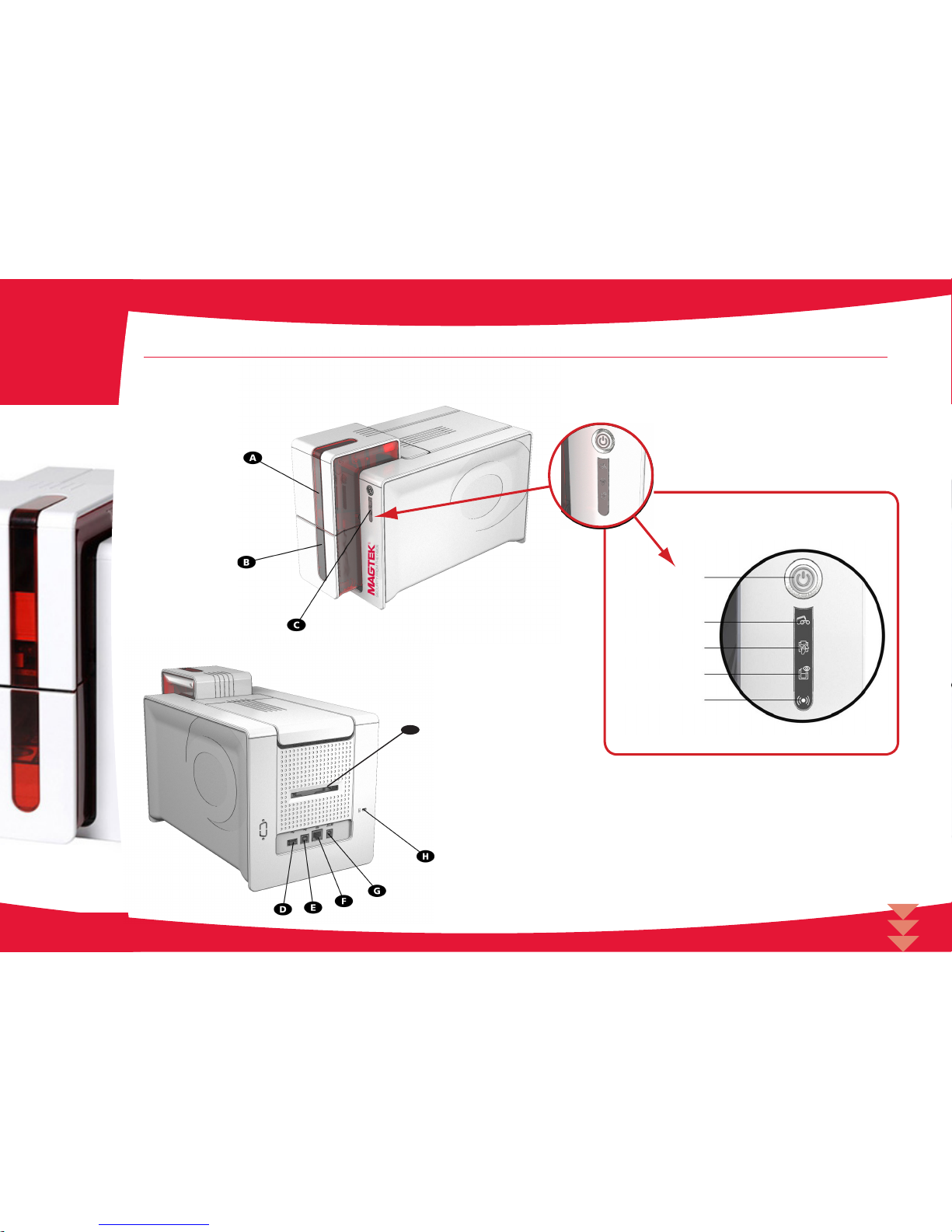
1-2 Description of the device and its functions
1
A - Card stock feeder
B - Card output hopper
C - Control panel
D - USB connector (type A)
E - USB connector (type B)
F - Ethernet connector
G - Power cable socket
H - Place for Kensington lock/security
anchor
I - Place for card rejection bin
Pushbutton
Cards and ribbon
Cleaning
Device
Wi-Fi (option)
I
Page 6
6
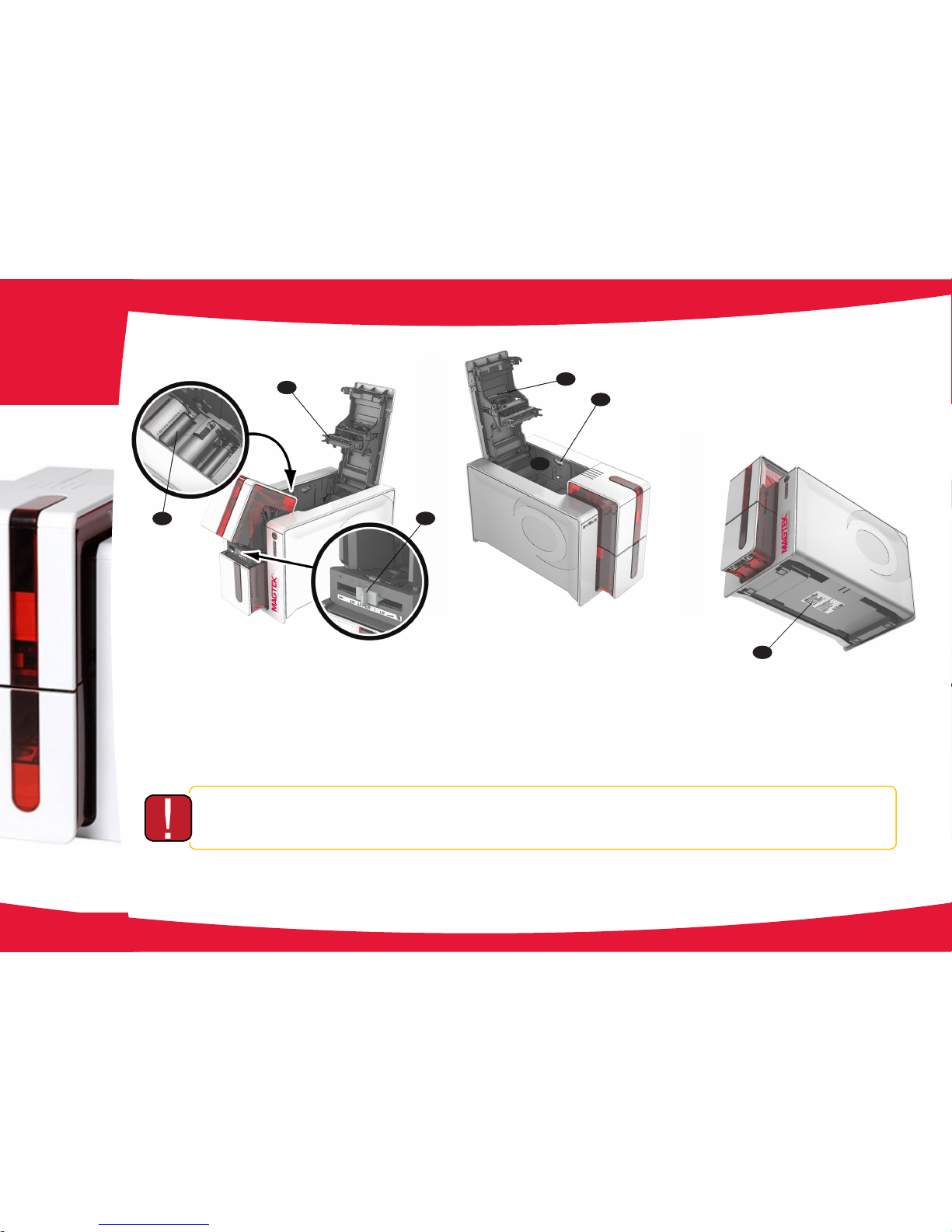
Access to the side panels of the device and the option module tting/removal areas is restricted to your retailer/installer or to experienced
users. The device should always be disconnected from the power supply (unplugged) before carrying out any work on it.
1
J - Thermal print head
K - Card cleaning roller
L - Card thickness adjustment gauge
M - Location for double-sided printing activation key
N - Dust Filter
0 - Side panel opening mechanism
P - Serial number label
J
K
L
M
N
P
O
Page 7

7
Printing
2-1 Installing the print driver
New advanced functions automate device conguration after the print driver has been installed.
To install a print driver, insert the CD into your computer and select the print driver menu. A program will guide you through the entire installation
process.
Do not connect your USB cable to your computer until prompted to do so by the installation program. For the connection procedure, see
the section on Connecting the Device.
Follow the installation procedure scrupulously. All versions of Windows and Macintosh require the user to have administrator rights to
install the driver.
The setup consists of:
1. Install the EC500p print drver
2. Connect/Congure the ExpressCard 500p printer
3. Install the ExpressCard 500p fonts
4. Install the QwickCards.com Device Controller
5. Import the EC500p/IS380 Client Certicates
6. Add EC500p/IS380 CPDs to QwickCards.com
7. Start the EC500p/IS380 Device Controllers
NOTE: Do NOT connect the device to a computer before installing print driver.
2
Page 8
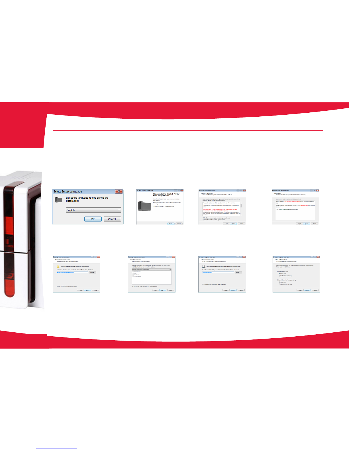
Select Lanaguage Press NEXT to continue installation. Select the radio button to accept warranty
agreement terms.
Press NEXT to continue installation.
Ensure the printer is NOT connected to the PC
during installation. If it is connected, disconnect it
before advancing.
Press NEXT to continue installation.
Accept the default installation location.
Press NEXT to continue installation.
Accept the default standard installation.
Select NEXT to continue.
Select Start Menu Folder. Accept default.
Select NEXT to continue.
Select default settings.
Select NEXT to continue.
8
2
2-1 Installing the Print Driver (continued)
Follow the installation procedure scrupulously. All versions of Windows and Macintosh require the user to have administrator rights to
install the driver.
Page 9

During installation, a progress bar is shown.
This may take a few minutes, so be patient.
When it completes, it will advance to the
next screen.
At this point, the program is ready to be
installed.
Press Install to begin the installation
process.
After the print drver has competed
installation, this completion screen is
shown.
Press the Finish button.
After the print drver has competed
installation, this screen is shown.
Don’t check the Ethernet settings (DHCP)
check box, Press the Next button.
Assemble the printer (cables, ribbon,
cards, …) and ready it for connection to an
available USB connector on the PC. The
print drver will be located and associated
with the printer; the printer will show up as
an available printer on the PC.
Press the Finish button. After the printer is connected to an
available USB port, the system will locate
the print drver.
After it is located, it will indicate that the
device is ready to use.
9
2-1 Installing the Print Driver (continued)
2
Page 10
10
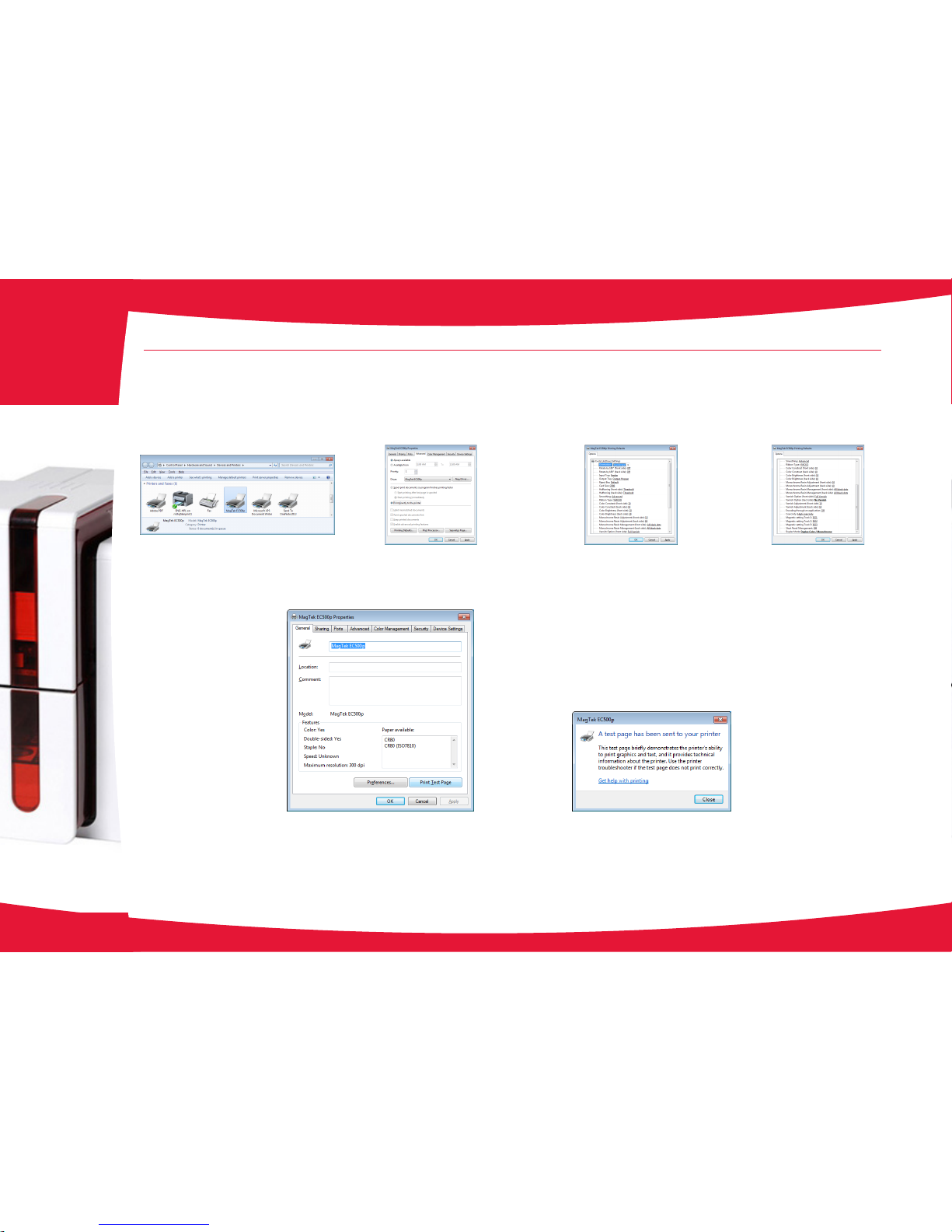
Highlight the Advanced tab and select the
Print Directly to the Printer radio button.
Press Printing Defaults button to bring up
the options selection screen.
Bring up the Printers and Faxes control panel.
Right-click on the EC500p/Evolis printer and select
Printer Properties from the menu.
Set Options.
Click OK.
Set Options.
Click APPLY.
2-2 Managing the print settings
2
Close the test page dialog screen and press
OK on the printer properties page.
This concludes the printer setup step.
Change the default settings to the values shown at the left.
Note: Depending on the type of ribbon being used, there may be
different selections required than are shown here. Contact Support
to assist you in the correct settings.
Press OK to accept the settings.
Highlight the General tab and select the Print Test Page button
to print a test page to the EC500p/Evolis printer to conrm
communication and printer quality.
Page 11

11
2-3 Managing the printer
•
Select the desired device.
•
Right-click the name of the device, select Properties to access the settings or double (left) click the name of the device.
Pay attention to the settings dened under the print driver Properties and do not hesitate to contact MagTek Support Services for any
advice and assistance needed before making any changes.
2
Page 12

12
2-4 Installing the Fonts
In order for the ExpressCard 500p to render the correct fonts for jobs downloaded from QwickCards.com, a number of new fonts must be
loaded on the host PC.
The fonts can be located on the CD in the folder: Disk1\Resources\ExpressCard 500p Fonts
Highlight all of the .TTF les in Windows Explorer, right-click and select Install from the menu.
Note: If using Windows XP, highlight all of the .TTF les in Windows Explorer and copy to fonts folder which performs the “install”:
C:\Windows\Fonts
If a prompt displays indicating that the font is already installed, select to install the newer version from the CD.
2
Page 13
13
Connecting the Device
3-1 Installation
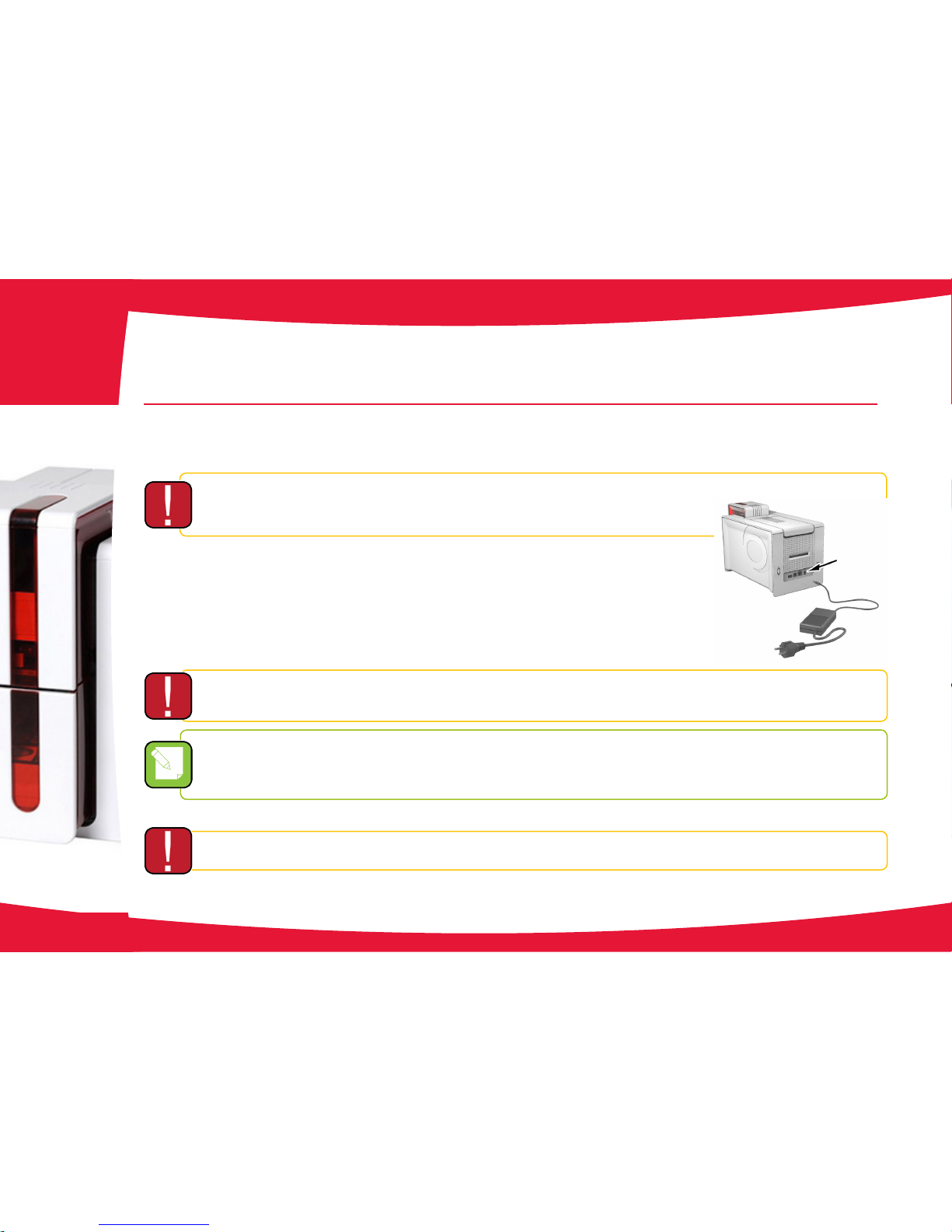
3.1.1 Connecting the Device
Connection to the power supply
The device must be connected to a properly protected and grounded socket outlet.
FI: Laite on liitettävä suojamaadoitus koskettimilla varustettuun pistorasiaan.
NO: Apparatet må tilkoples jordet stikkontakt.
SE: Apparaten skall anslutas till jordat uttag.
1.
Connect the power cable to the power supply unit, then plug the power supply unit connector into
the device.
2.
Plug the end of the power cable into a grounded power socket.
3.
The device is powered on: the control panel lights up showing the device is working properly. If the
control panel does not light, then either installation has not been carried out correctly or the device
is not working properly. Check the installation.
Before attempting any maintenance, ensure that the power cable is always unplugged. For your personal safety, ensure that the cable and
power supply unit remain easy to access, especially in the event of an emergency.
To save energy, the device will automatically switch itself to standby mode after 10 minutes of inactivity. The device switches to hibernation
mode after 30 minutes in standby mode.
The standby times can be congured in the MagTek Print Driver. In standard standby mode, sending a print request restarts the device and
quickly pressing on the button for 1 second exits the device from hibernation mode.
Connecting the USB cable
Under no circumstances should you connect the USB data cable before installation of the device driver is complete.
Refer to the section on device driver installation for further details, and follow the instructions carefully.
3
Page 14
14
3.1.2 Ribbons
Original High Trust® ribbons optimize your device’s operation and avoid causing damage to it. The use of ribbons from other suppliers is liable
to damage your device and voids the manufacturer’s warranty for the device.
For optimum print quality, MagTek recommends fully cleaning the device every time the ribbon is changed. See the Servicing and Maintenance
section of this manual.
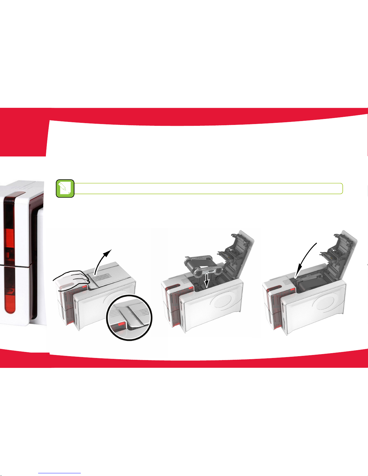
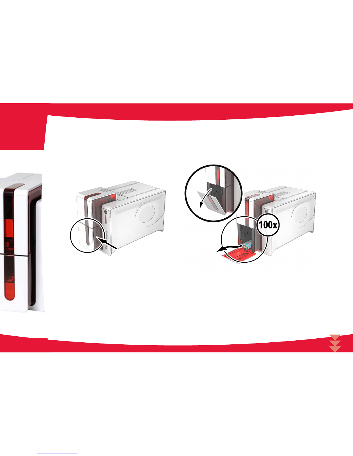
Installing the ribbon
The device automatically recognizes the ribbon inserted.
1.
Open the access door.
2.
Insert the ribbon as shown.
3.
Close the access door and press until you feel a click.
3
2 3
1
Page 15
100x
15
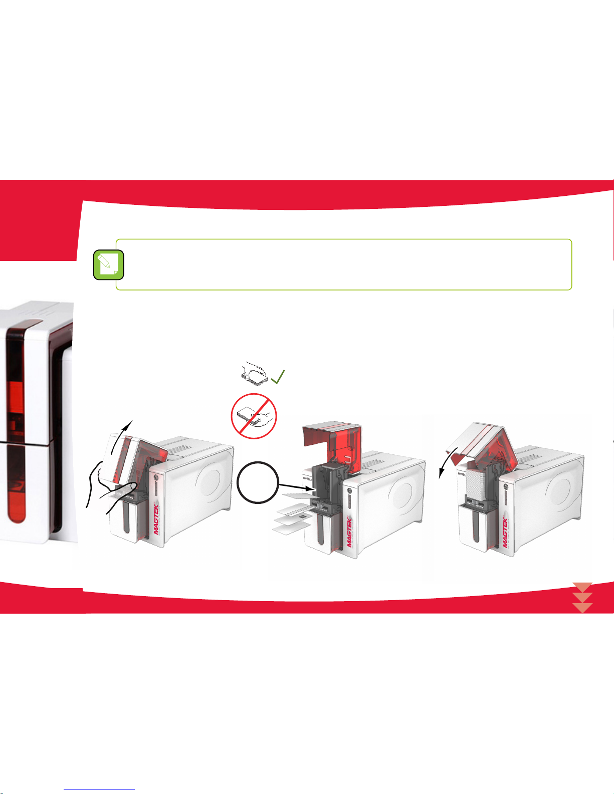
3.1.3 Card
For optimum quality, the cards used must be ISO 7810 certied.
Use only the card types recommended by MagTek.
Do not touch the printable surface of the cards in order to preserve print quality.
Do not use cards that have been damaged, folded, embossed or dropped on the oor.
Keep your cards protected from dust.
Loading the cards
1.
Open the card feeder.
2.
Insert the cards, a maximum of 100 cards of thickness 0.76 mm. Ensure the cards are positioned as illustrated in the diagram.
3.
Close the feeder.
3
1 2 3
Page 16
16
Removing printed cards
After the print cycle is complete, cards are delivered into the card output hopper below the card feeder. This card output hopper is designed to
collect the printed and/or encoded cards. The device is equipped with an card output hopper with a maximum capacity of 100 x 0.76 mm cards.
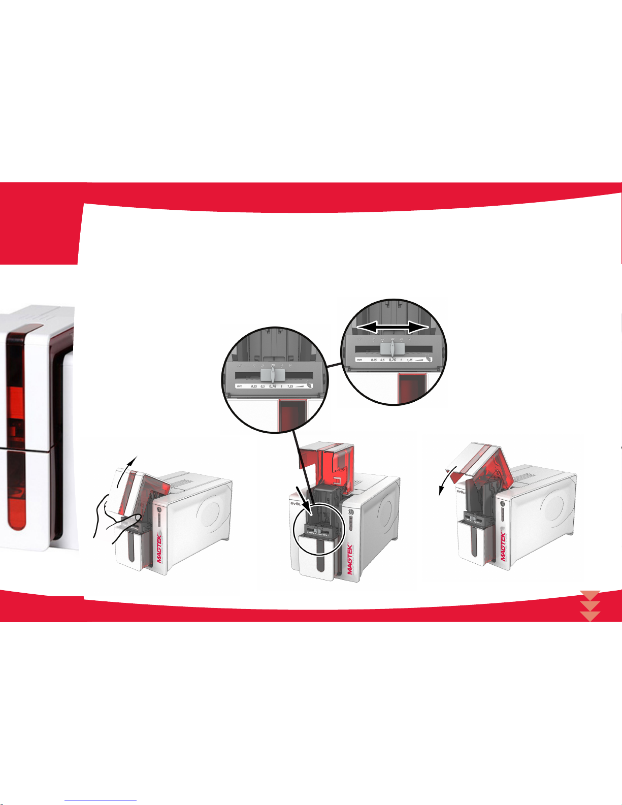
Adjusting card thickness
The device is equipped with a manual card thickness adjustment mechanism which can be reached through the card feeder when open. The
device accepts cards between 0.25 mm and 1.25 mm thick (10 to 50 mil). The factory setting is 0.76 mm.
3
Page 17
17
To adjust card thickness:
1.
Open the card feeder on the device.
2.
Adjust the thickness of the cards used by moving the gauge from right to left to the desired card thickness.
3.
Close the feeder.
3
1
3
2
Page 18
18
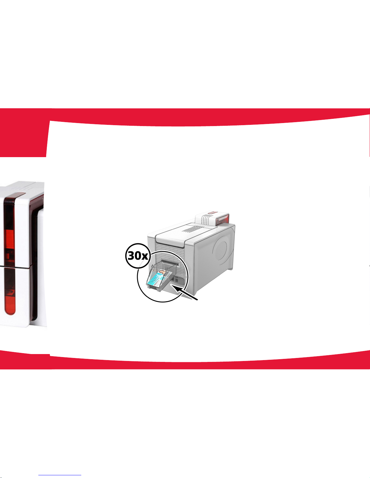
Managing the card rejection bin
The device is tted with a removable card rejection bin which is positioned behind it.
The card rejection bin can hold 30 cards.
To empty it, just remove the cards in it.
MagTek recommends that you empty this bin regularly and securely dispose of the rejected cards.
3
Page 19

19
4
4-1 QwickCards.com Device Controller
4.1.1 installing the Device Controller
The current IS380 Device Controller has been modied to support both the IS380 and EC500p devices; it has been renamed
QwickCards.com Device Controller. Before installing the QwickCards.com Device Controller, ensure you have completed the following:
1. If you have the IS380 Device Controller installed, uninstall it before running the QwickCards.com Device Controller setup program.
2. Request an EC500p Client Certicate from Support. This is the same procedure you followed for the IS380. You have to have a Client
Certicate .pfx le matching your EC500p.
3. If you do not already have an IS380 Client Certicate .pfx le, request an IS380 Client Certicate from MagTek Support Services and have
it available during the QwickCards.com Device Controller setup.
Locate the QwickCards.com Device Controller setup software and execute it.
It is located on the CD in:
\Disk1\SetUp.exe
Page 20
20
4
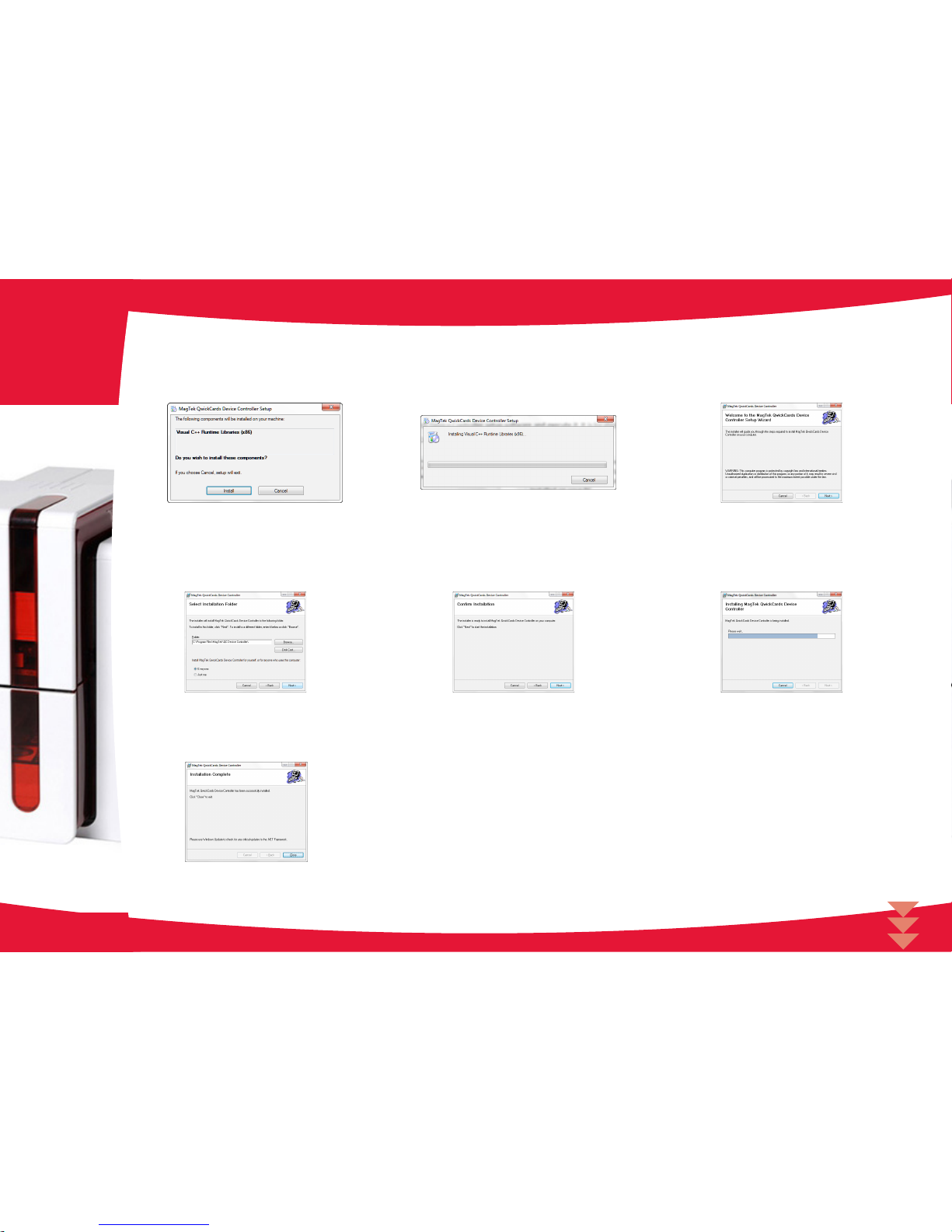
4.1.1 Installing the Device Controller (continued)
While the Microsoft Visual C++ 2008
Redistributable library is being installed, the
progress screen shown at the left is displayed until
it has been installed.
The EC500p printer library requires the Microsoft Visual
C++ 2008 Redistributable library. You may be prompted
for this library if it is not already installed on the host
PC. Press INSTALL to download and install the Visual
C++ Runtime Libraries.
This screen is used to indicate the location where
the QC Device Controller is to be installed. Leave
the defaults as is; press the NEXT button to
continue.
This screen indicates the start of the QwickCards.
com Device Controller installation process. Press
the NEXT button to continue.
While the QwickCards.com Device Controller is
being installed, the progress screen shown at the
left is displayed until it has been installed.
The installer has all of the information it needs.
Press the NEXT button to continue.
After the QwickCards.com Device Controller has
competed installation, this completion screen is
shown. Press the CLOSE button.
Page 21

21
4
4.1.2 Configuring the Device Controller
At this time the QwickCards.com Device Controller has been installed on the PC.
There are 2 shortcuts added to the desktop:
• IS380 Device Controller
• EC500p Device Controller
Before you can run either Device Controller, you must congure the Client Certicate(s) for each of the devices. You need to have the
“serialized” .pfx certicate le for each device before you can use them. In addition, you need to install your IS380 / EC500p device on
QwickCards.com before you send jobs to them.
Note: The QC Device Controller must be started from the desktop icons. Because it needs to be run as Administrator, the shortcut needs to be
modied so it starts the QC Device Controller as administrator. Right-click on the desktop icon, and check “Run this program as an administrator” on
the Compatibility tab, then press OK button.
Page 22

22
4
4-2 EC500p Device Controller
4.2.1 Installing the Device Controller
Locate the EC500p Client Certicate associated with the serial number of the EC500p. Copy it into the folder where the QC Device Controller
was installed so it is ready to be used by the CerticateUtility program.
Run the CerticateUtility program and select the .pfx le and password. Ensure it was opened successfully.
When the EC500 Device Controller shortcut is used to start the QC Device Controller, it should detect the EC500p Device, get its Serial
Number and compare it to the EC500p Client Certicate that was previously set up with the CerticateUtility program, and establish a
secure SSL connection to the QwickCards.com Job Server.
The QC Device Controller.exe.Cong le has a number of EC500p related parameters which might need to be changed:
<add key=”JobInterval” value=”10” /> --How often to check for jobs
<add key=”EvolisName” value=”MagTek EC500p” /> --Name of the EC500p printer
<add key=”Path” value=”C:\MagTek\QC Device Controller\” /> --Where temp les are placed
Page 23

23
4
4.2.2 Starting the Device Controller
After the CPDs have been added and activated on QwickCards.com, the individual Device Controllers may be started.
The EC500p Device Controller continually polls the QwickCards.com Jobs Server for jobs queued to it.
The IS380 Device Controller waits for a card to be inserted and then queries the QwickCards.com Job Server to determine whether there is a
job queued matching the card that was read in.
After the Device Controller(s) have been started, users can send Issue Card and RePIN Card transactions to the devices.
Page 24

24
4
4.2.3 User Interface for the Device Controller
The EC500p User Interface is similar to the IS380 User Interface (which is documented in the IS380 Device Controller User Guide).
The following screenshots describe the various states presented by the program.
2. If the Job Server indicates there is a job pending
for this EC500p, the Device Controller retrieves the
job from the Job Server.
1. When the EC500p Device Controller begins,
it gets the Serial Number from the printer and
compares it to the EC500p Client Certicate
and establishes a secure SSL connection to the
QwickCards.com Job Server. It will periodically poll
the QwickCards.com Job Server to see if there is a
job queued for this EC500p.
4. After the job has been completely sent to the
EC500p device, the Message display reects that
the job was completed successfully which indicates
that the Device Controller has reported back to the
Job Server that the card was successfully created.
It then returns to the System Idle message as
shown in point #1.
3. After the job has been received from the Job
Server (including the images congured to print on
the card), the Device Controller begins processing
the job locally and directing it to the attached
EC500p device.
6. If the EC500p Device Controller loses
communication with the printer, the status LED
turns red and the Message indicates the possibility
that the printer is unplugged or is not powered on.
5. Before an EC500p device can be used on the
system, it must added to the system and activated.
If this error is shown when the EC500p Device
Controller is started, it indicates that it has not
been added/activated. When that activity has been
completed, restart the EC500p Device Controller
program.
7. If the EC500p Device Controller detects that the
hopper is empty, the status LED turns red and the
Message indicates an error reecting the fact that
the card hopper is empty.
Page 25

25
4
4.2.4 Troubleshooting for the Device Controller
When the EC500 Device Controller enters into an error state (red LED) while processing a job, it reports back to the QwickCards.com Job
Server that the job was not processed successfully (the job will be sent to the Exception Queue) and it will not poll the QwickCards.com
Job Server for jobs. The cause of the printer error (being off-line, out of cards, ribbon problem, …) must be corrected before new jobs are
requested.
After correcting the error condition, press the Restart button to have the controller re-establish communication with the printer and begin
polling for jobs. Re-submit the job from the QwickCard Job Server exception queue to the pending job queue and the printer will retrieve the
next job from the QwickCards.com Job Server.
Page 26

1
2
3 4
26
4
4-3 Double-sided Printing
If your device prints on only one side of the card and you want to print on both sides, you can obtain a double-sided printing upgrade by contacting MagTek
Support Services. The kit comprises an activation key which must be inserted into the device. This operation is quick and easy to do.
Follow the procedure below:
1.
Turn on your device. It must not be turned off or on standby.
2.
Open the device access door.
3.
Remove the device ribbon.
4.
Insert the key as shown in the diagram.
Page 27

1 2 3
4
27
1.
Close the access door again. The 3 LEDs on the control panel start ashing one after the other for between 5 and 10 seconds. Activation
has completed successfully when the 3 LEDs remain lit for several seconds then turn off.
2.
Open the access door (1) and remove the activation key (2).
3.
Ret the ribbon.
4.
Close the top access door.
4
Page 28

28
5-1 Routine device cleaning
5.1.1 Routine Device Cleaning Notes
The print head warranty is directly linked to routine cleaning of your device.
If you do not carry out this cleaning at the required times, the print head warranty will cease to be valid.
Recommended cleaning cycle: whenever the ribbon is changed
Mandatory cleaning cycle: when the cleaning warning is triggered
Servicing accessory : adhesive cleaning card.
Your device is tted with a cleaning warning system which is triggered after a certain number of car ds have been inserted.
You should proceed with the routine cleaning of your device as soon as the warning is triggered.
If you continue to run the device despite the warning and if the warning light remains lit, the print head warranty will be automatically voided owing to a failure to comply
with your contractual maintenance obligations.
Device
Cleaning required after:
(warning light ashing)
Number of cards remaining before
warranty voided
(warning light steady)
Warranty invalid after:
(warning light steady)
ExpressCard 500p 1000 cards 200 cards 1200 cards
5
Page 29

MAX
29
5.1.2 Routine Device Cleaning Details
Follow the procedure below to ensure you have carried out regular cleaning properly:
Repeatedly running the adhesive card through the device cleans the cleaning roller in order to maintain print quality and increases the service
life of the print head.
•
Open the device access door.
•
Remove the ribbon as shown on the diagram.
•
Close the access door and check it has clicked shut.
•
Open the feeder of the device.
•
Using the lever, set the card thickness to the MAX position.
5
3
2
4
1
5
Page 30

30
1.
Remove any cards present in the feeder.
2.
Double click the cleaning button on the control panel before inserting the cleaning card.
3.
Remove the lm from the adhesive card 3 and insert the cleaning card into the feeder as shown, adhesive side up 4. Cleaning starts.
4.
The used cleaning card is ejected automatically into the card output hopper.
Routine cleaning may also be carried out from the MagTek Print Driver by clicking on “Start cleaning”.
Before using your device, remember to reset the gauge to the desired card thickness.
5
1 2
3
4
Page 31

31
5.1.3 Servicing the Print Head
Recommended cleaning cycle: whenever the ribbon is changed.
Servicing accessory: special cotton bud impregnated with isopropyl alcohol.
However, to maintain the original print quality and to absorb surplus ink on the print head, we recommend that you regularly clean the print head
(whenever the ribbon is changed and during the routine cleaning) using the cotton buds supplied by MagTek.
You must also protect the print head and its components from any discharge of static electricity.
Unplug the device from its power supply before cleaning the print head.
Follow the cleaning cycles scrupulously.
Avoid any contact between the print head and any metal or sharp objects.
Avoid touching the print head directly with your ngers, as this could affect print quality or permanently damage the print head.
5
Page 32

32
Follow the procedure below:
1.
Take an MagTek cotton bud and press the middle of the tube until the end of the cotton bud is impregnated with alcohol.
2.
Unplug the power supply cable, open the access door then nd the print head.
3.
Gently rub the cotton bud from left to right along the print head for a few seconds.
4.
Close the access door. Reconnect the device.
5. Wait for 2 minutes after cleaning before using your device.
5
1
3
2
4
Page 33

33
5-2 Advanced Cleaning
For a more in-depth clean, we recommend carrying out an advanced clean every ve routine cleaning cycles.
MagTek provides a MagTek High Trust® maintenance kit consisting of 2 adhesive cards, 2 impregnated “T” shaped cards, a cleaning pen and a box of 60 wipes.
The “T” shaped card is used to clean the card feed rollers and the magnetic encoder head. To ensure advanced cleaning is carried out properly, the procedure
given below must be followed.
5.2.1 Device Cleaning
Recommended cleaning cycle: every 5 routine cleaning cycles.
Servicing accessory : impregnated “T” shaped card and adhesive card
Follow the procedure below:
1.
Open the device access door.
2.
Remove the ribbon as shown on the diagram.
3.
Close the access door and check it has clicked shut.
4.
Open the card feeder on the device.
5
1 32 4
Page 34

MAX
34
5. Using the lever, set the card thickness to the MAX position.
6. Remove any cards present in the feeder.
7. Double click the cleaning button on the control panel before inserting the cleaning card.
8. Take the “T” shaped cleaning card and insert it in the feeder as shown. Cleaning starts.
5
5
7
6
8
Page 35

35
9. Remove the “T” shaped card, then remove the lm from the adhesive cleaning card and insert the cleaning card into the feeder as shown,
adhesive side up. Cleaning starts.
10 .The used adhesive card is ejected automatically into the card output hopper.
Routine cleaning may also be carried out from the Print Driver by clicking on “Start cleaning”.
Warning, the T shaped card must be used immediately after the package is opened.
11. Wait for 2 minutes after cleaning before using your device. Before using your device, remember to reset the gauge to the desired card thickness.
5
9 10
Page 36

36
5.2.2 Servicing the Print Head
Recommended cleaning cycle: every 5 routine cleaning cycles.
Servicing accessory : cleaning pen
Unplug the device from its power supply before cleaning the print head.
Follow the cleaning cycles scrupulously.
Avoid any contact between the print head and any metal or sharp objects.
Avoid touching the print head directly with your ngers, as this could affect print quality or permanently damage the print head.
The cleaning pen can be used up to 8 times for cleaning the print head.
Follow the procedure below:
1.
Remove the access door from the cleaning pen.
2.
Unplug the power supply cable, open the access door then nd the print head.
3.
Gently rub the pen from left to right along the print head for a few seconds.
4.
Close the access door. Reconnect the device.
5. Wait for 2 minutes after cleaning before using your device.
5
1 32 4
Page 37

37
5.2.3 Servicing the Dust Filter
The dust lter is located above the print head fan. This lter can become fouled up over time and it is recommended to clean it
once a year or every 10,000 cards depending on your working environment.
1.
Open the device access door. Locate the dust lter.
2.
Remove the lter by pulling it upwards and slide it out to release it completely.
3.
After the lter is removed from its slot, obtain a cleaning wipe supplied by MagTek.
4.
Clean the lter by rubbing the wipe on either side of it.
5.
Re-install the dust lter by inserting it in its slot (notch towards you) and lower it until you feel a click indicating it is correctly positioned.
6.
Close the access door.
5
1
3
2
4
5
6
Page 38

38
Help
This section gives a number of suggestions for pinpointing problems that may arise when using your device. If you do not
manage to solve your problem, this section also explains how to contact MagTek Support Services.
6-1 Warnings and Troubleshooting
Although the MagTek device was designed to work independently, keeping user involvement to a minimum, it may nonetheless
prove useful to gain some familiarity with the main warnings.
See section 1 - Description of the device and its functions for further details about the control panel.
6
OFF
STEADY LIGHT
FLASHING
Pushbutton
Cards and ribbon
Cleaning
Device
Wi-Fi (option)
Page 39

39
6
•
The device is ready to
receive data.
•
No ribbon in the device.
•
End of ribbon.
•
The ribbon is not correctly
tted.
•
The ribbon is torn.
•
The ribbon is not recognized.
Check the condition of the ribbon in
the device. If you have a print job in
progress, this restarts with a new car d.
•
The device is receiving data.
•
No cards in the card feeder.
Put cards back into the feeder - the
process starts again.
•
Card loading error.
Check cards have been loaded. For
any other problem contact MagTek.
Device READY
RIBBON
PROCESSING
CARDS
Page 40

40
6
•
The device access door is
open.
Close the access door again. The
device starts up.
Device Access Door Open
•
Card jammed in the device.
•
Mechanical component
fault.
Open the access door and hold down
the push button in order to eject the
jammed card. For more details, refer
to section 4-3b.
If the problem persists, contact
MagTek Support Services for
assistance.
MECHANICAL ERROR
•
The device requires
advanced cleaning.
See section 3 - Maintenance
ADVANCED CLEANING
•
The device must be
cleaned.
See section 3 - Maintenance
ROUTINE CLEANING
(after 1,000 cards have been inserted)
•
The device must be cleaned
to avoid the risk of the
warranty being voided.
See section 3 - Maintenance
CLEANING
(after 1,200 cards have been inserted)
Page 41

41
6
•
The cooling system has been
activated.
The device pauses for a few seconds
and restarts af ter it has returned to its
normal operating temperature.
•
The device is updating its
Firmware.
The device restarts following the
update.
COOLING MODE
WAITING FOR A CARD
TO BE INSERTED OR REMOVED
FIRMWARE UPDATE
•
The device is waiting for
a card to be inserted or
removed.
Insert a card or remove the card from
the manual feeder (see section 1 Getting started)
•
The wireless (Wi-Fi)
connection has been
enabled.
You can start printing.
Wi-Fi IS ON (option)
Page 42

42
6
6-2 Troubleshooting Help
In this section, you will nd all the information you need to carry out a few simple checks that you may be asked to run by MagTek Support Services to help
you as effectively as possible.
6.2.1 Printing a Technical Test Card
The technical test card must be printed when you receive your device to ensure your device is operating correctly. This card shows various items of technical
information concerning the device (serial number, rmware, cleaning operations, print head, etc.). You may be asked for these by Support Services.
•
Wait for any current print jobs to nish.
•
Check that there is a ribbon and card stock in the device.
•
Press the pushbutton for four to ve seconds until it turns off.
•
Press and hold down the pushbutton again.
•
The power button light comes on.
•
Release the pushbutton after the light ashes.
•
The test card is printed (in color if a color ribbon is tted in the device, or monochrome if the ribbon is monochrome, and on both sides if
the double-sided printing function has been enabled).
•
The printed card is ejected into the card output hopper.
Printing the technical test card can also be launched from the MagTek Print Driver.
6.2.2 Printing a Graphic Test Card
The graphic test card is used to check the print quality in color or monochrome, the offsets and whether the ribbon is synchronized correctly.
To print the graphic test card, check rst of all that a ribbon and a card are present in the device.
Go to MagTek Print Driver, select System information and click on the Test cards tab. Then click the Graphic test card button. The card is printed and the
printed card is ejected into the card output hopper.
Printing the graphic test card can only be launched from the MagTek Print Driver.
Page 43

43
6.2.3 Identifying Installed Software Versions
You can identify directly the system versions installed (print driver, set, etc.).
•
In the MagTek Print Driver, double click the name of the device to display its Properties.
6
Page 44

44
6-3 Troubleshooting
Do not attempt to use tools or other items to repair your device in the event of problems, in case major damage is caused.
6.3.1 Printing Problems
Nothing prints
• Check the print driver
• Check that there is a print driver for your device in the Windows conguration.
• Check that the device is selected as the default device.
• Check the device’s power supply
• Check that the power cable is correctly connected to the device and to a working electrical socket.
• Check that the device is on and that the pushbutton is lit.
• Make sure you are using the power supply unit supplied with the device.
• Check the USB cable
• Check that the USB cable is connecting the device to your computer.
• Check the ribbon
• Check that the ribbon is tted correctly and that the access door is closed.
• Check the cards
• Check that there are cards in the card feeder.
• Check that no cards are jammed in the device.
• Print a test card
• See elsewhere in this section for the procedure to be followed
• Blank card ejected
• Check the ribbon
• Check that the ribbon is not nished or damaged. Replace it or re-install it if necessary.
• The print head may be damaged
• Print a test card.
• If the test card does not print, contact MagTek Support Services for technical support or visit the website at www.MagTek.com.
6
Page 45

45
Poor print quality
Small blemishes on the card
• The card surface may be dirty.
• Check that your cards are perfectly clean.
• Use new cards.
• Cleaning roller or print head clogged.
• Run a cleaning cycle.
Horizontal white lines
• The ribbon is not correctly tted.
• Check that there are no wrinkles on the ribbon surface.
• Print head dirty or damaged.
• Clean or replace the print head.
Blurred image
• The ribbon is not correctly tted.
• Check that the ribbon is correctly positioned in the device.
• Poor ribbon synchronization.
• Open and close the device access door to synchronize the ribbon.
• Dirty device or cleaning roller.
• Clean the device.
• Use of incompatible cards.
• Check that the cards used match the specications.
6
We recommend that you obtain your cards from MagTek. Use of cards obtained elsewhere is liable to adversely
affect print quality and/or damage the print head.
Page 46

46
Partial or incorrect printing
Check the print settings
• Check that no area of the card design to be printed is outside the print margins.
• Check the document orientation (portrait or landscape) in the MagTek Print Driver conguration.
Check the interface cable
• If irregular characters are printed, check that you are in fact using the USB cable supplied with your device.
• Check the connection between the computer and the device.
• Try using another cable of the same type.
Check that the device is clean
• Clean the device, especially the cleaning roller.
• See the maintenance section.
Check that the cards are clean
• Store your cards protected from dust.
Check the ribbon
• Check that the ribbon is tted correctly.
• Check that the ribbon spools freely.
Check the print head
• Should horizontal straight lines appear on printed cards, it is likely that the print head is dirty or damaged.
• See the section on maintenance and troubleshooting.
If the problems persist, contact MagTek Support Services or visit the website at www.MagTek.com.
6
Page 47

47
6.3.2 Freeing Jammed Cards
Control panel displays:
Do not turn off your device as this cancels pending print jobs in the device’s memory.
Remove the card as follows:
•
Open the device access door and remove the ribbon.
•
Press the pushbutton to turn the card transport rollers. If the card is still stuck inside the device, slide it manually towards the device
output. If there is more than one card, always push the top one rst.
•
Replace the ribbon, then close the device access door.
To prevent card jams:
•
Check that the card thickness gauge is correctly adjusted.
•
Check that the thickness of the cards used matches the specications set out in Appendix A “Technical specications” in this manual.
•
Check that the cards are at. Keep them in a horizontal position.
•
Check that the cards are not stuck together. Shufe the cards before loading them.
6
•
Card jammed in the device. Print jobs are interrupted.
Mechanical Error
Page 48

48
6.3.3 Replacing the Print Head
The print head is a sensitive component of your equipment. It determines the print quality, and regular servicing along with an immediate
environment free from dust or other particles ensure a lengthy useful life. Nonetheless, the print head may sometimes need to be replaced. The
EC500ps unique design enables users to undertake such replacement with no tools needed, simply by following the instructions very carefully.
Before doing anything else, please contact MagTek Support Services in order to check the advisability of replacing the print head. MagTek will
supply a new print head if need be.
6
Page 49

49
To exchange the print head, please proceed as follows:
Before changing the print head, please unplug the power cable.
Step 1 - Removing the defective print head
1.
Open the device access door.
2.
Locate the print head.
3.
Press on the plastic part behind the head (pressure plate) and pull on the head with the other hand as shown in the diagram in order to
free the lugs from the holding fork, then remove the lugs from their slots.
4.
Tilt the head carefully downwards and disconnect the connector linked to the cable without using force on the mechanism.
6
1
3
4
2
Page 50

50
Step 2 - Installing the new print head
1.
Note the code shown on the white label stuck on the print head. You will be asked for this code in Step 3.
2.
Take the new head and insert it vertically (white connector upwards) raising it in the two guides so as to trap the lugs of the fork in their
slots. Then lower it by pressing on the two forks, a click will be heard.
3.
Connect the cable into its socket, making sure it is the right way round. Do not use any force, as this part is relatively fragile. Press down
on each side of the connector to ensure a good connection is made.
4.
The head is back in position.
5.
Close the access door. The print head is now tted.
6
1
4
5
2
3
Page 51

51
Step 3 - Configuring the new print head
1.
Power up the device and check that it is properly connected to a computer on which the device’s MagTek Print Driver is installed.
2.
In Maintenance of MagTek Print Driver, click on the Change print head tab.
3.
Enter the PKN number of the print head kit in Enter PKN no., the number you noted down in step 2. Then click Conrm.
If the print head kit number is not entered correctly, device malfunctions may occur and the warranty may be voided.
Step 4 - Cleaning the device
On your device’s control panel, the “CLEANING” light is lit:
Cleaning is absolutely necessary after c hanging the print head. No print jobs can be run until the cleaning operation has nished.
Refer to section 3 – Maintenance to carry out cleaning.
After cleaning has been carried out, your device is ready to customize your cards.
4. Wait for 2 minutes after cleaning before using your device.
6
CLEANING
Page 52

52
6.3.4 Updating Firmware (Windows)
Updating the rmware is a simple operation but one which, if not properly completed, can result in your device breaking down.
Before any update, please contact MagTek Support Services who will be able to guide you on the advisability or otherwise of carrying out an upgrade. In
general, such updates are only required in the event of problem or malfunction that has been clearly identied by MagTek Support Services.
Updates can be downloaded from the website at www.MagTek.com:
1. Go to the Support & Drivers menu, then select your device model and click on the Print drivers and Firmware link.
2. Then click on the le for the corresponding Firmware.
3. Accept the download then save the le in a directory on your hard drive. The rmware is stored compressed as a zip le, which you will
need to extract.
4. Then double-click on the le in the directory in order to run the rmware installation program.
5. When requested by the program, follow the instructions in order to select the device and start the operation. The rmware download is
in progress.
6. After about thirty seconds, the rmware has transferred to the device and the operation is complete.
7. If the device is not showing a ‘READY’ status, this means that the update has not been carried out correctly or, possibly, that the device
is not working properly. Check the connection cables and run a new update.
The update is complete, and your equipment is ready to customize your cards.
Never interrupt the transfer between computer and device during the download phase (powering off the device or computer, unplugging a cable). This would result in
a complete inability to restart the device. Should such an incident occur, please contact MagTek Support Services, who will replace your device’s processing board.
The update of the rmware can be carried out from the MagTek Print Driver.
6
Page 53

53
6.3.5 Updating the Print Driver
Updating the print driver is a task that is required in order to x malfunctions or gain the benet of new options.
Before any update, please contact MagTek Support Services who will be able to guide you on the advisability or other wise of carrying out an upgrade.
Updates can be downloaded from the website at www.MagTek.com:
1. Go to the Support & Drivers menu, then select your device model and click on the Print drivers and Firmware link.
2. Then click on the le for the corresponding print driver.
3. Accept the download then save the le in a directory on your hard drive. The rmware is stored compressed as a zip le, which you will
need to extract.
4. Then double-click on the setup.exe le that you have just downloaded in order to run the installation program.
For more details about the procedure, please see the Installing the print driver section.
6
Page 54

54
6-4 Technical support
If you are having difculties in conguring and using your device, read this manual carefully.
If you do not manage to solve your problem, you can obtain further information and help from MagTek Support Services.
6.4.1 MagTek Support
For any unresolved technical problem, contact MagTek Support Services. When calling, please be close to your computer and ready to provide the following
information:
•
Your device model and serial number
•
The conguration and operating system that you are using
•
A description of the incident that has occurred
•
A description of the steps that you have taken to resolve the problem.
In addition, to enable you to nd answers to your questions 24/7, the www.MagTek.com website includes a number of aspects related to day-to-day use of your
device.
6.4.2 Finding Information on www.MagTek.com
If you need additional technical help, you will nd a great deal of information on using and troubleshooting MagTek devices under the Drivers and Support
section on the MagTek website at www.MagTek.com.
This section offers downloads of the latest versions of rmware, print drivers and user manuals, videos about using and maintaining MagTek devices, and an
FAQ* section giving answers to the most frequently asked questions.
*
FAQ: Frequently Asked Questions
6
Page 55

55
Appendix A
A-1 Technical specications
This section presents your device’s technical printing properties.
General technical features
• Single side or double sided print module, edge-to-edge printing
• Color sublimation and monochrome thermal transfer
• 300 dpi print head (11.8 dots/mm)
• 16 million colors
• 16MB RAM
Printing speed
Full card print
• YMCKO 190 cards/hour
• YMCKO-K 140 cards/hour
• Monochrome 600 cards/hour
Maximum speed (under special conditions)
• Color up to 210 cards/hour (single side)
• Monochrome up to 850 cards per hour (single side)
Card management and technical data
• Automatic or manual feeder
• Feeder capacity: 100 cards (0.76 mm – 30 mil)
• Card output hopper capacity: 100 cards (0.76 mm – 30 mil)
• Card rejection bin: 30 cards (0.76 mm – 30 mil)
• Card thickness: 0.25 to 1.25 mm (10 to 50 mil), adjustment using the gauge (0.25 mm/10 mil for monochrome printing only)
• Card types: PVC and composite PVC cards, PET, recycled PET cards, ABS
1
and special clear overlaid cards
1
• Card format: ISO CR80 - ISO 7810 (53,98 mm x 85,60 mm)
1
Under specic conditions
A
Page 56

56
Ribbons
To maximize the quality and lifetime of the printed cards, the service life of your print head and the overall reliability of your device, use High Trust®
ribbons.
• Automatic identication and setting
• Ribbon inserted in a cassette to make handling easier
• Graphic notication of the ribbon level (almost nished, nished)
• Integrated ribbon saving for monochrome printing
• Ribbons:
• YMCKO: 300 prints/roll
YMCKO-K: 200 prints/roll
• 1/2 YMCKO: 400 prints/roll
• KO: 600 prints/roll
• Monochrome ribbons: 1000 prints/roll
1
• Hologram ribbon: 400 prints/roll
1 Under specic conditions
Ports/connectivity
• USB 1.1 (compatible 3.0)
• Optional 802.11b/g wireless connection
Display
• LEDs
• Graphic device notications
1
:
• Feeder empty
• Cleaning alerts
• Ribbon nearly nished/nished warning
• Etc.
1 Dependant on your version of Windows
Software
• Supplied with MagTek Premium Suite® for Windows:
• Device driver
• MagTek Print Driver for the administration, management and conguration of the device
• MagTek Device Manager for two-way graphic notication
1
• Compatible with Windows
2
(from XP SP3)
• Supplied with cardPresso XXS
• Supplied with Mac OS X device driver (from 10.5)
• Linux platform on request
• SDK available on request
1 Requires .net 4.0 client prole version
2 For older versions of Windows, you can only use the device via a device driver.
A
Page 57

57
Dimensions and weight
• Dimensions (H x W x L): 247 x 205 x 381 mm
• Weight: 4.02 kg
Acoustics (tested in accordance with ISO 7779)
• Sound pressure in assistant positions
LpAm
(color mode YMCKO)
• In operation: 48 dB (A)
• Standby mode: background noise level
Security
• Place for Kensington® lock
• Data encryption for magnetic encoding
Eco-design and certications
• Standby mode and reduced power consumption
• Device meets the Energy Related Products Directive, ErP, 2009/125/EC
Contents of the packaging
• Device
• CD-ROM with device driver, user manuals, cardPresso XXS
• Cleaning equipment
• USB cable
• Card rejection bin
• Power supply unit
• Power supply lead (differs according to region)
A
Page 58

58
Options & accessories
• Colors available: Fire red
• Double-sided printing upgrade kit
• Encoding options
• Can be combined, tted on site using additional modules
• Magnetic stripe encoder
• Chip contact station
• Smartcard encoder
• Contactless card encoder
• Others on request
Certications and declaration of conformity
• CE, FCC, IEC, VCCI, CCC, KC
• ErP 2009/125/CE, RoHS
• 13.56 MHz, PLL/ASK/semi-duplex operation
Power supply
• Power supply module: 100-240 Volts AC, 50-60 Hz, 1.7A
• Device: 24 Volts DC, 2.7 A
Environment
• Min/max operating temperature: 15° / 30 °C (59° / 86 °F)
• Humidity: 20% to 65% without condensation
• Min/max storage temperature: –5° / +70 °C (23° / 158 °F)
• Storage humidity: 20% to 70% without condensation
• Ventilation in operation: open air
A
Page 59

59
Appendix B
B-1 Encoding options
Some models of MagTek devices are equipped with encoding systems which are used to customize magnetic stripes, and contact and contactless
smartcards.
B.1.1 - MAGNETIC STRIPE ENCODING
A device tted with a magnetic encoder works in exactly the same way as a basic card device. The MagTek encoder encodes the magnetic stripes
in a single pass then runs a data check.
Although able to be congured as high coercivity (HiCo) or low coercivity (LoCo) by a simple click in MagTek Print Driver, MagTek magnetic
encoders come factory set for high coercivity (HiCo).
Location of the magnetic encoder
The magnetic encoder is a module installed either in the factory or on site by a MagTek Authorized Service Provider. The read and write head is
located under the path taken by the cards and before the print head. The encoding sequence for a card is always carried out before the printing.
Use only magnetic stripe cards that comply with ISO 7810 and ISO 7811 standards.
The magnetic stripe must be molded into the card to work properly.
Never use cards with a glued-on magnetic stripe.
B
Page 60

60
Card positioning
Magnetic stripe cards must be placed in the card feeder so that the magnetic stripe is facing downward as shown below:
1.
Open the device card feeder as shown.
2.
Insert a maximum of 50 cards of thickness 0.76 mm. Hold the cards as shown in the diagram (magnetic stripe downwards).
3.
Close the feeder.
B
1 32
Page 61

61
Configuring the MagTek Print Driver
When rst installing the MagTek Print Driver, the magnetic encoder functions need to be congured. The magnetic encoder functions may be
accessed from the MagTek Print Driver Properties by right-clicking the name of the device.
Magnetic Encoder dialogue box
The Magnetic Encoding dialogue box is opened by clicking Encoding followed by Magnetic.
Congure stripes allows you to select the desired format for each stripe. See the table in
this Appendix for information regarding ISO 7811 standards.
Coercivity sets the magnetic encoding to high (HiCo) or low (LoCo) coercivity. A magnetic
stripe that is encoded with high coercivity is more resistant to external disturbance than a
magnetic stripe encoded using low coercivity.
Encoding via an application is used to encode magnetic stripe cards from applications
under Windows (such as Word for example). A text eld enclosed within “|” and “|”
characters (or some other character which the user can dene) will be interpreted as an
encoding command by print driver.
Selecting Maintenance then Dialog with the magnetic encoder, Magnetic encoding allows
one or more magnetic stripes to be directly encoded from this window simply by selecting
them and entering the data to be encoded. Click on the Encode stripe(s) button to run the
encoding cycle.
B
Page 62

62
Cleaning the magnetic encoder
The magnetic encoder head requires regular maintenance in order to ensure the integrity of the data encoded onto cards.
Cleaning of the magnetic encoder is carried out when the device runs an advanced cleaning sequence with impregnated cards (see the
“Maintenance” section of this manual for further information).
Repeatedly running the cleaning card through the device cleans the card feed rollers, the cleaning rollers, the print head and the magnetic
encoder read-write head.
If, in between two routine device cleaning runs (every 1000 cards inserted), the read-write process fails with more than one card, it is recommended
to run an advanced device cleaning sequence manually (please see the “Maintenance” section of this manual for the procedure to follow).
ISO 7811 magnetic encoding standards
1
Dots per inch
2
Except for the “?” character
3
Including the Start, Stop and LRC characters These characters are automatically handled by the magnetic encoder
Stripe number Separator Density Character set Number of characters
Stripe 1 ^ 210 ppp
1
Alphanumeric
(ASCII 32-95)
2
79
3
Stripe 1 = 75 ppp
1
Numeric
(ASCII 48-62)
2
40
3
Stripe 1 = 210 ppp
1
Numeric
(ASCII 48-62)
2
107
3
B
Page 63

63
B.1.2 - Contact Smartcard Encoding
A device tted with a smartcard contact station works in exactly the same way as a basic card device. The MagTek smartcard contact station is used to program
chips to ISO 7816-2 standards.
Contact station location
The contact station is a module installed either in the factory or on site by a MagTek Authorized Service Provider. It is located over the path taken by the cards
and after the print head. To contact the smartcard, the contact station descends mechanically against the smartcard. The programming sequence for a chip
is always carried out before the card is printed.
Use only smartcards compliant with the ISO 7816-2 standard.
Never print over the chip.
B
Page 64

64
Card positioning
Smartcards must be placed in the card feeder so that the chip contact is facing upwards as shown below:
1.
Open the device card feeder as shown.
2.
Insert a maximum of 50 cards of thickness 0.76 mm (smartcard contact upwards). Ensure the cards are positioned as illustrated in the
diagram.
3.
Close the card feeder.
B
1 2 3
Page 65

65
Contact station interface
Devices tted only with a smartcard contact station (without integrated encoder)
are tted with a female DB-9 connector which is found on the back of a device. This
connector, directly connected to the contact station inside the device, is also connected
to an external coupler to program the chip.
A sequence of commands must be sent via the device’s interface to insert a card into the device then position it under the station and establish
contact.
DB-9 connector pins Smartcard contact points
1 C1 (V c.c.)
2 C2 (reset)
3 C3 (clock)
4 C4 (reserved)
5 C5 (ground)
6 C6 (Vpp)
7 C7 (I/O)
8 C8 (reserved)
9 Card present signal
B
Page 66

66
The command sequence is as follows:
Sending the SIS sequence:
l A card is moved from the feeder to the contact station, and stops underneath it.
l The contact station is pushed downwards to make contact with the card.
l The device connects the contact station to the DB-9 connector.
l The chip can be programmed via the external coupler.
B
Page 67

67
B.1.3 Contactless Smartcard Encoding
MagTek devices may be equipped with an encoding device for contactless smartcards (RFID). This consists of an encoding module and a built-in
antenna.
A module such as this must be installed by a specialist. The MagTek product catalog includes devices equipped with a built-in encoder for
contactless chips.
This encoder connects to the PC via a USB interface.
There is a very wide variety of contactless smartcards, and each card has specic technical properties associated with an equally specic type
of encoder.
Location of the antenna (or the encoder including an antenna)
By means of a specic command, the card is positioned close to the antenna such that the card lies within its radio range.
Reading data from or writing data to the card can then start.
The programming sequence for a chip is always carried out before the card is printed.
Card positioning
There is in theory no restriction on card positioning when programming in contactless mode.
However, the miniaturization of components is bringing about the emergence of cards tted with mini-antennae.
If this is the case, please see your card supplier for further information about where such mini-antennae are located within the card, so as to
position the card as close as possible to the encoder’s antenna. Doing so will ensure optimum encoding of the cards.
B
Page 68

68
Computer connection
If your encoder is supplied with an USB interface, it will either be connected to the device’s internal USB Hub, or equipped with a USB cable to
connect to your computer directly.
In the rst case, your device’s USB cable is used to drive rstly the device and secondly the encoder from the computer.
If your encoder is supplied with an RS-232 interface, it needs to be connected to the computer via a serial cable. This cable plugs into the
device’s female DB-9 socket, and into a COM port on the computer.
A sequence of commands must be sent via the device’s interface to insert a card in the device then position it close to the antenna to establish
radio communication between the card and the encoder.
The command sequence is as follows:
Sending the SIC sequence:
l A card is moved from the feeder towards the antenna and is positioned nearby.
l The chip is programmed via the computer’s serial (or USB) interface connecting the built-in encoder and the computer.
DB-9 connector pins RS-232 signals (serial)
1 Not used
2 RxD
3 TxD
4 Not used
5 GND
6 Not used
7 RTS
8 CTS
9 Not used
B
 Loading...