

Page 1
Excella
Small Document Scanner
Quick Installation Guide
www.magtek.com
Registered to ISO 9001:2000 © Copyright 2015 MagTek, Inc. PN D99800048 rev 20 8/15
MagTek ® Inc., 1710 Apollo Court, Seal Beach CA 90740 p 562-546-6400 | f 562-546-6301 | 800-788-6835 | www.magtek.com
When high performance check processing is an integral part of your application, Excella delivers both the speed and
efciency you need. Excella is the ideal desktop check reading device for early-image capture and programmable
endorsement message in high-volume electronic check applications, including BOC, Check 21 and remote deposit capture.
With a small footprint and striking modern design, Excella is an auto-feed check reader which captures both the front and
back image of checks in a single pass at 45+ DPM. The automatic feeder has a capacity of up to 70 documents to easily
support even the most active check processing applications. The easy-maintenance, high-speed unit is API and protocol
compatible with MagTek’s Excella STX single-feed scanner for optimum application exibility.
Note: More detailed instructions can be found in Excella’s Installation and Operation Manual (P/N 99875310).
Product Description
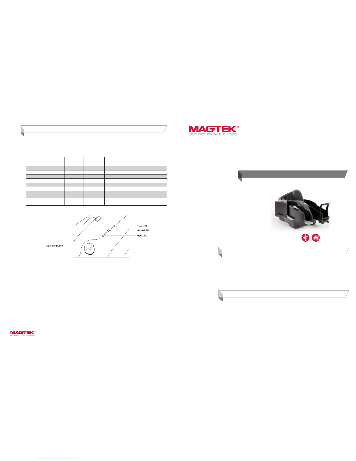
Troubleshooting/LEDs
The LED indicators are shown in Figure 5. All three LEDs are able to show three colors: green, red, or amber. Each LED indicator has been
assigned a specic reporting function (see Table 1 below):
• Front LED: reports MICR read status
• Middle LED: reports path status
• Rear LED: reports unit status
Front LED
(MICR status)
Middle LED
(Path status)
Rear LED
(Unit status)
Description
Amber Amber Amber Unit is initializing
Green Green Green Power on, everything is OK
X X Flash Amber Initializing network connection
Flash Red X X After check read: MICR read error
Flash Green X X After check read: good MICR read
Flash Red/Green X X MICR noise detected (if enabled): relocate unit
X Amber X Left or right access door unlatched (if feature is in-
stalled): close and latch access guides
X Flash Red X Paper jam: remove jam and hit operator button to
clear
Figure 5. LED Indicators
Power and Installation
The following is a summary of the major installation steps for Excella:
1. Unpack Excella.
2. Install ink cartridge (the cartridge is shipped uninstalled).
3. Insert API/Demo CD in drive and install the Demo software.
4. Connect interface cable (USB or Ethernet) and power cable to Excella.
5. Connect power cord to AC wall outlet.
6. Connect interface cable to PC.
7. Depending on your interface, continue with USB INSTALLATION or ETHERNET INSTALLATION below.
Page 2
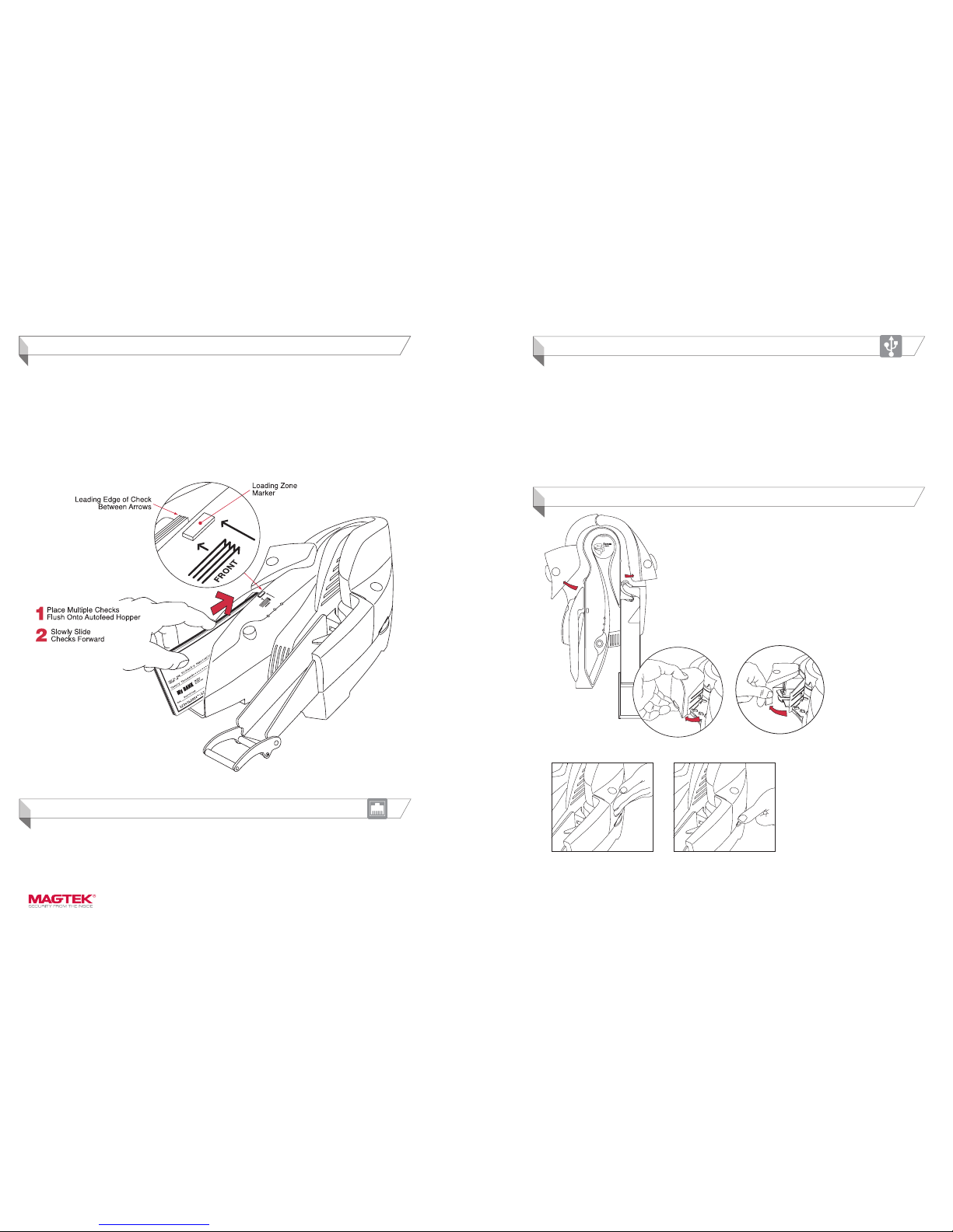
Figure 2. Opening the Left and Right Access Doors
USB Connection
Operation
www.magtek.com
The following is a summary of the installation steps for Excella with a USB interface:
1. Ensure the API/Demo CD is inserted in the drive.
2. When the PC detects the new USB device, follow the instruction wizard instructions.
3. When prompted, point to the CD as the source for the drivers.
4. After the drivers have been successfully installed, run the “ExcellaUSBCong” utility. On the PC, this utility can be found on the folder:
C:\Program Files\MagTek\Excella Demo.
5. For “Excella Device” select the USB Device ID shown. For example, the default USB ID is “USB\VID_0801&PID_2230\123”.
6. For “Excella Device(s) in MICRDEV.INI le”, choose the default “EXCELLA_USB”.
7. For “IP Address(PC Side)”, use the default address or enter a new address like 192.168.x.y (NOTE: “x” and “y” are numbers between
2-254; pick “x” to avoid IP address conicts).
8. For “IP Address (Device Side), use the default address or enter a new address like 192.168.x.z. (NOTE: “x” and “z” are numbers
between 2-254; “x” must be the same as in step 7; “z” must be different than “y” in step 7).
9. For “Subnet Mask”, enter a new Subnet Mask or use the default: 255.255.255.0.
10. Click on “Apply”.
11. Click on “OK” and close the utility.
Ethernet Connection
Excella is a web appliance and it offers several functions and features in a built-in Web page accessible through a Web browser. For
example, if Excella’s default Ethernet device IP address is 192.168.10.100, type the “http://192.168.10.100” in your web browser to access
Excella’s web page.
On the main menu, the Conguration page offer options to setup the Network and Ethernet congurations. Additionally, an option is
provided to save and restore device congurations.
Figure 1. Stacking Checks in Input Hopper
PREPARING THE CHECKS
When you have a deck of checks that needs to be processed, prepare the checks as described below:
1. Grab the entire deck of checks and lightly tap the bottom of the deck against a at surface with the objective of
aligning the bottom edge of all the checks in the deck.
2. Also, grab the entire deck of checks and lightly tap with your hand the right edge of the deck with the objective of
aligning the leading edge of all the checks in the deck.
FEEDING CHECKS AUTOMATICALLY
The Input Hopper can hold up to 70 checks. To feed a deck of checks, proceed as follows:
1. Stack the checks in the Input Hopper as shown in Figure 1.
2. Slide the deck forward to the Loading Zone Marker so that all leading edges are between the arrows as shown in
Figure 1.
Opening and Closing the Unit
OPENING THE UNIT
The Left Access Door, the Right Access Door and the Printer/Cartridge Cover, shown in
Figure 2, can be opened to provide access to the check path and both scan bars. Open
the unit as described as follows:
• Open the Left Access Door by placing the thumb on the Indent and the nger(s) on
the Tab as shown in Figure 2 and squeezing, and then gently pull the Door open.
• Open the Right Access Door, in the same manner, by placing the thumb on the
Indent and the nger(s) on the tab, and squeezing and then gently pull the guide
open.
• Open the Printer/Cartridge Cover by pulling the Cover from the Left Door as shown
in Figure 3.
Figure 3. Separating the Printer
Cover from the Left Access Door
Figure 4. Closing the Unit
CLOSING THE UNIT
If the Left Access Door or the Right Access Door has
been opened, close the access door as described
below:
• Push to close the access door (Left or Right) to its
normal operating position (as show in Figure 4).
• If the Printer/Cartridge Cover is open on the Left
Access Door, rst close the printer cover and
then close the access door as described in step
1 above.
• Push down on the tab of the access door (as
shown in Figure 4) If the tab was not latched,
a “click” sound will be heard as feedback to
indicate the access guide is securely closed.
• The LED indicator will ash if the access door is
improperly closed (see Table 1).
 Loading...