

Page 1
Technical Bulletin (Document Number 99875631)
Rev Number
Date
Notes
1.01
09/12/2013
Initial Release
2.01
9/20/2013
Add information on coordinates, font spacing, font sizes
ExpressCard 2000 Tipping and Emboss Areas
Technical Bulletin
ExpressCard 2000 Tipping and Emboss Areas
Document Number 99875631
1 Introduction ............................................................................................................................. 2
2 Tipping and Emboss Areas ..................................................................................................... 2
2.1 Caution About Emboss and Tipping Areas ..................................................................... 2
2.2 EC2000 Tipping Area ...................................................................................................... 2
2.3 Converting Measurements To XML Coordinates ........................................................... 3
Table 1.1 - Revisions
MagTek I 1710 Apollo Court I Seal Beach, CA 90740 I Phone: (562) 546-6400 I Technical Support: (888) 624-8350
www.magtek.com
Page 2
Technical Bulletin (Document Number 99875631)
ExpressCard 2000 Tipping and Emboss Areas
1 Introduction
The ExpressCard 2000 (EC2000) provides features for embossing characters on cards and for tipping
those embossed characters with foil. Introductions to embossing and foil tipping are provided in
99875600 ExpressCard 2000 User Installation and Operation Manual, and details for developing
custom card designs are provided in 99875611 ExpressCard 2000 Programming Reference Manual /
Windows XML Specification. This technical bulletin provides supplemental information pertaining to
the emboss and tipping areas of custom card XML designs created using that reference.
2 Tipping and Emboss Areas
2.1 Caution About Emboss and Tipping Areas
The emboss and tipping areas of the EC2000 are governed by ISO/IEC 7811. To allow customers
additional flexibility for custom applications, the EC2000 will allow embossing outside the area defined
by that standard, but MagTek Engineering strongly recommends only creating card designs that fall
within that area. Non-conformant designs can cause issuance and usage problems, including cards that
could prematurely wear out card feeding mechanisms, or jam in card slots and conveyors.
2.2 EC2000 Tipping Area
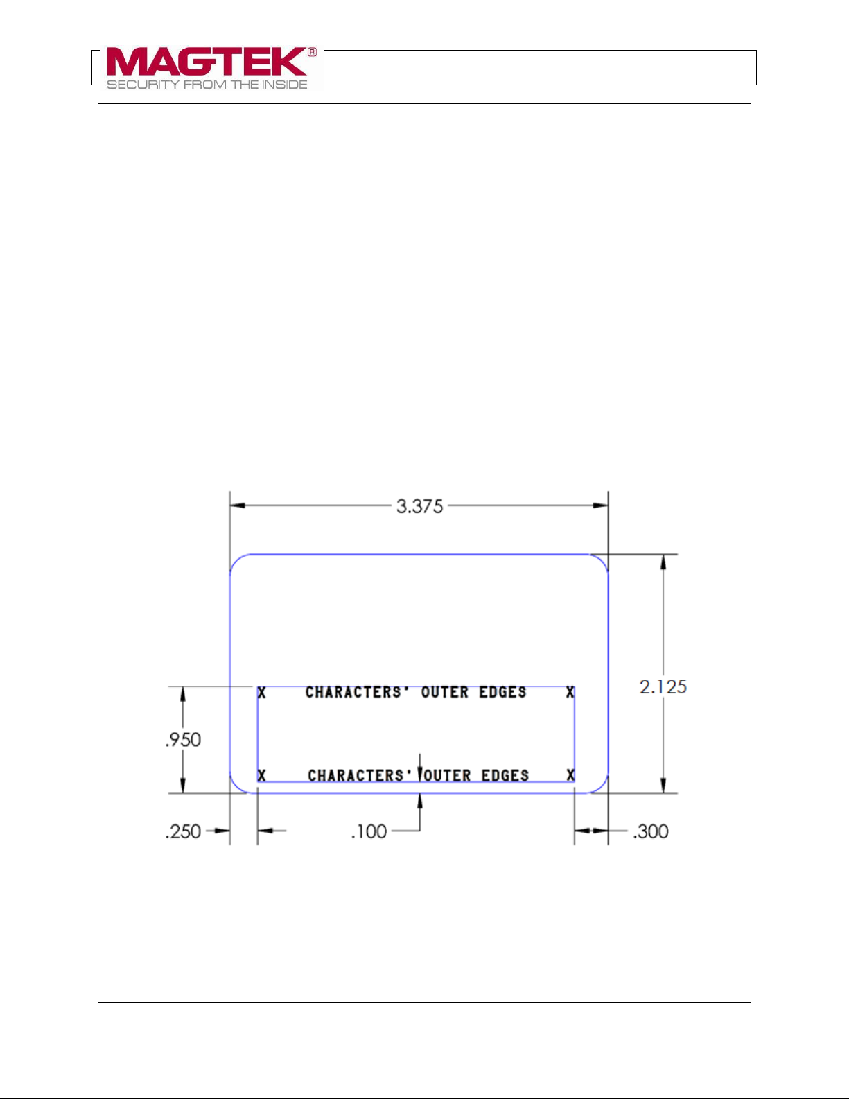
The outer boundaries where the EC2000’s foil tipper can cover a CR80 card are shown in Figure 2-1.
Figure 2-1 - Tipping Area Defined by Character Edges
To make sure a design stays within the specified boundaries, developers must take into account font
dimensions and spacing, device calibration, string lengths, and so on. Some experimentation, testing, and
careful measurement are generally necessary during the design process to make sure the XML will
produce the desired results in all use cases.
MagTek I 1710 Apollo Court I Seal Beach, CA 90740 I Phone: (562) 546-6400 I Technical Support: (888) 624-8350
www.magtek.com
Page 2
Page 3
Technical Bulletin (Document Number 99875631)
ExpressCard 2000 Tipping and Emboss Areas
2.3 Converting Measurements To XML Coordinates
When developing custom XML, it is often necessary to convert physical measurements in a design or
specification into EC2000 XML coordinates. This section provides details to assist with conversion.
It is important to note that the placement and scaling of the coordinate system are affected
by settings found in the Tuning (Embossing) page, so it is advisable to perform
measurements to find the actual coordinate system origin (0,0) for your application.
2.3.1 Coordinate System and Distances
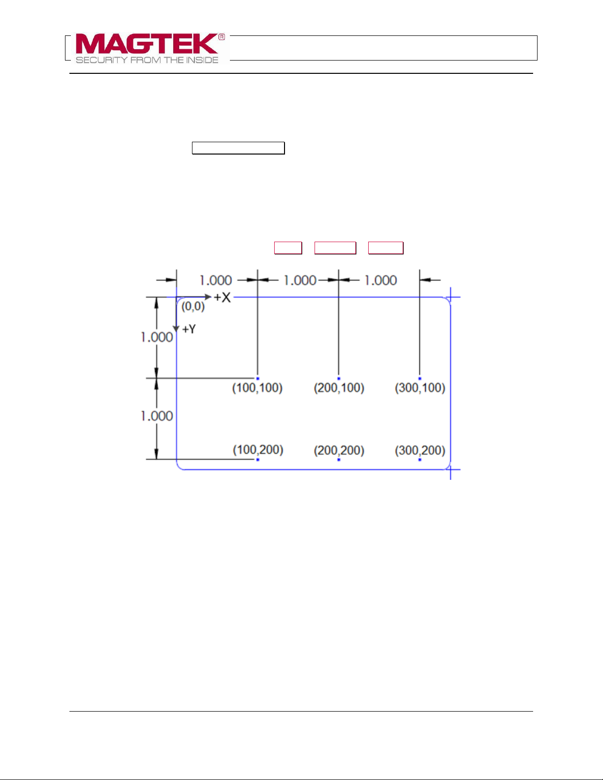
EC2000 XML coordinates are specified in 0.01 (1/100) inch increments. For example, the distance
between the point (10,200) and the point (11,200) is 0.01 inches. The theoretical boundaries of a CR80
card are therefore from (0,0) at the upper left corner to approximately (337,212) at the lower right corner.
The exact placement of the origin depends on the EC2000’s calibration settings – primarily the Card
Offset X and Card Offset Y settings found in Menu > Settings > Tuning.
Figure 2-2 - EC2000 Coordinate System
Knowing the origin and coordinate system size, it becomes straightforward to find the approximate
locations of the tipping area boundaries shown in Figure 2-1:
Left boundary at X = 25
Right boundary at X = 307
Upper boundary at Y = 117
Bottom boundary at Y = 202
2.3.2 Character Placement
The EC2000 places the upper left corner of a character at the coordinates specified in the XML. If your
design specifies character centers, you must take the nominal font height and width into account when
choosing coordinates.
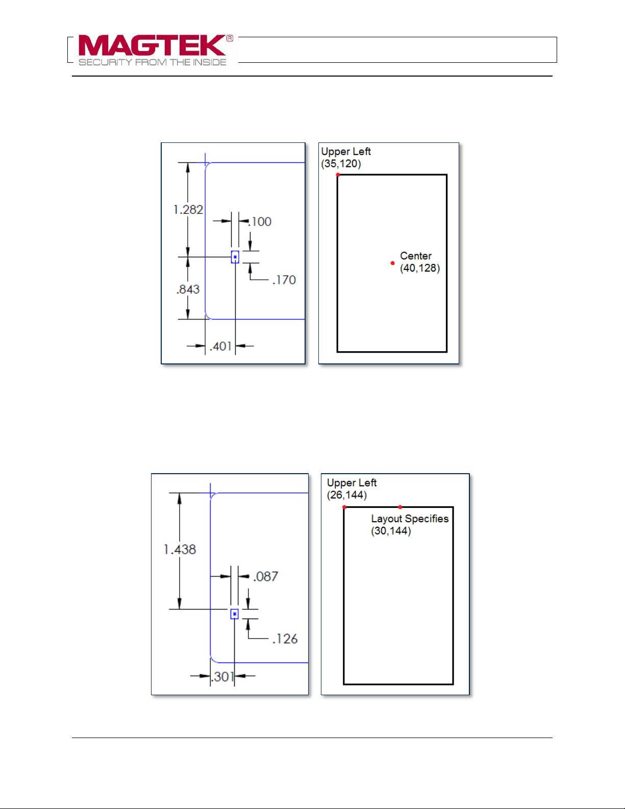
For example, Figure 2-3 shows a design where the position of the first character in the Primary Account
Number (PAN) is specified by its centerpoint at a position that translates to coordinates (40, 128).
FontID1 has a nominal character height of 0.17 inches and a nominal character width of 0.10 inches, so
MagTek I 1710 Apollo Court I Seal Beach, CA 90740 I Phone: (562) 546-6400 I Technical Support: (888) 624-8350
Page 3
www.magtek.com
Page 4
Technical Bulletin (Document Number 99875631)
ExpressCard 2000 Tipping and Emboss Areas
you would start with XML that places the upper left corner 0.17/2 inches higher and 0.10/2 inches further
to the left than the centerpoint, giving coordinates (35,120). To account for calibration and other factors,
you should then measure the actual character position on an issued card, and adjust the XML until the
character is embossed in the specified location.
Figure 2-3 - FontID1 Layout Measurements to XML Example
Figure 2-4 shows a second design where the position of the first character in the name string is specified
by its top boundary and horizontal center at a position that translates to (30,144). FontID2 has a nominal
character height of 0.126 inches and a nominal character width of 0.087 inches, so you would start with
XML that places the upper left corner 0.087/2 inches further to the left than the layout point, giving
coordinates of (26, 144). Measure and adjust the XML as in the previous example.
Page 4
Figure 2-4 - FontID2 Layout Measurements to XML Example
MagTek I 1710 Apollo Court I Seal Beach, CA 90740 I Phone: (562) 546-6400 I Technical Support: (888) 624-8350
www.magtek.com
Page 5

Technical Bulletin (Document Number 99875631)
ExpressCard 2000 Tipping and Emboss Areas
2.3.3 Characters Per Inch
Given a fixed starting coordinate for an embossed string, determining the length of string that will fit
within the boundaries requires understanding the nominal and configured characters per inch (CPI) value
for each of the four fonts on the embosser wheel.
The CPI value for each font can be found by navigating to Menu > Settings > Tuning > Advanced… .
The settings on that page labeled FontID1, FontID2, FontID3, and FontID4 show the number of
thousandths of an inch the embosser will place between the centers of characters in an embossed string
that uses that font. The CPI for a given font can be calculated by dividing 1000 by that number.
For example, if FontID1 is set to a value of 143, the EC2000 will place 143/1000 inches between each
character. Inverting that gives 1000/143 characters per inch, or 7 CPI. Nominally, FontID1 (Farrington
7B) is specified as a 7 CPI font, and FontID2 (Standard Gothic) is specified as a 10 CPI font.
2.3.4 Maximum String Lengths
The final consideration when managing boundaries is the absolute length limit of strings: Regardless of
placement, FontID1 has a maximum string length of 22 characters; FontID2 has a maximum string length
of 30 characters; FontID3 and FontID4 have “soft” maximum string lengths of 35 characters.
Page 5
MagTek I 1710 Apollo Court I Seal Beach, CA 90740 I Phone: (562) 546-6400 I Technical Support: (888) 624-8350
www.magtek.com
 Loading...