

Page 1
ExpressCard 2000
Instant Issuance Card Personalization System
Hardware Service Manual
June 2014
Manual Part Number:
99875607-4.01
REGISTERED TO ISO 9001:2008
MagTek I 1710 Apollo Court I Seal Beach, CA 90740 I Phone: (562) 546-6400 I Technical Support: (888) 624-8350
www.magtek.com
Page 2
Copyright © 2006 - 2014 MagTek, Inc.
Rev Number
Date
Notes
1.01
12/11/2013
Initial release derived from 99875357-6.01, 33099078-2.01,
99875617-1.01, MagTek Support Services videos
2.01
01/14/2014
Add removal / replacement for tipper heater, hopper module,
exit transport module, exit ramp and tipper module, MLB,
power controller, embedded PC, power supply, MSR,
touchscreen. Update some figures with improved renderings.
Add orientation to cardinal directions. Incorporate warnings
and re-order to support tipper cooling time. Re-order
Replacement and Adjustments chapters for more logical crossreferences. Improve cover removal/re-install instructions.
Add time estimates for replacements. Make terminology and
order of steps more consistent. Start section for
troubleshooting service-only issues. Add introduction to
embosser alignment. Update cleaning photos. Add sensor
diagram. Improve content about security of consumables. Fix
image printer replacement structure. Add details about top
deck plate keys / slots.
3.01
05/05/2014
Fix minor formatting issues; add step to move hopper
transport before removing side access doors; add advisory to
not pinch wires when removing left side access door.
4.01
06/27/2014
Update troubleshooting information about uneven tipping;
general updates to tipper heater replacement.
Printed in the United States of America
Information in this publication is subject to change without notice and may contain technical inaccuracies
or graphical discrepancies. Changes or improvements made to this product will be updated in the next
publication release. No part of this document may be reproduced or transmitted in any form or by any
means, electronic or mechanical, for any purpose, without the express written permission of MagTek, Inc.
MagTek® is a registered trademark of MagTek, Inc.
MagnePrint® is a registered trademark of MagTek, Inc.
Magensa™ is a trademark of MagTek, Inc.
MagneSafe™ is a trademark of MagTek, Inc.
ExpressCard 2000 is a trademark of MagTek, Inc.
Microsoft® and Windows® are registered trademarks of Microsoft Corporation.
All other system names and product names are the property of their respective owners.
Table 0.1 - Revisions
ExpressCard 2000| Instant Issuance Card Personalization System | Hardware Service Manual
Page 2
Page 3

SAFETY
This product has been evaluated by multiple safety certification agencies, including
Underwriters Laboratories (UL) and the United States Federal Communications
Commission (FCC Class A and Class B), and is designed to protect both the user and the
device. This document is written specifically to work in conjunction with these safety and
integrity features to protect the user and the device. It is very important to follow all steps
in the product documentation carefully, in the order in which they are described, and at
the recommended times. Failure to do so could result in personal injury, and / or cause
damage to the device, and / or void the product warranty.
The information within this manual has been prepared for use by trained professional
service personnel and is not intended for general use. To maintain the safety and integrity
of the machine, follow the procedures described in this manual carefully.
For your personal safety and to prevent damage to the device, disconnect power from the
device before you connect or disconnect any cable, electronic board, or assembly.
SAFETY REQUIREMENTS
Caution: Never do any of the following:
DO NOT use a ground adapter plug to connect equipment to a power socket-outlet that lacks a ground
connection terminal.
DO NOT attempt any maintenance function that is not specifically described in this manual or in
other ExpressCard 2000 instructional documents published by MagTek.
DO NOT override or “cheat” electrical or mechanical interlock devices.
DO NOT use EC2000 supplies or cleaning materials for other than their intended purposes.
DO NOT operate the equipment if you or anyone else have noticed unusual noises or odors.
Consider the following before operating the ExpressCard 2000:
Connect the EC2000 to a properly grounded AC power socket-outlet. If in doubt, have the socket-
outlet checked by a qualified electrician. Improper connection of the device’s grounding conductor
creates a risk of electric shock.
Place the EC2000 on a solid surface that can safely support the device’s weight support the weight of
the EC2000 PLUS the weight of a person leaning against the device (such as a service technician).
Be careful when moving or relocating the device. Use proper lifting techniques.
Use materials and supplies specifically designed for MagTek devices. Using unsuitable materials
may result in poor performance, and in some cases may be hazardous.
ExpressCard 2000| Instant Issuance Card Personalization System | Hardware Service Manual
Page 3
Page 4

0 - Table of Contents
Table of Contents
Table of Contents ............................................................................................................................... 4
1 Required Tools, Materials, and Documents ........................................................................... 7
1.1 Required Tools ..................................................................................................................... 7
1.2 Suggested Tools .................................................................................................................. 7
1.3 Required Materials ............................................................................................................. 7
1.4 Suggested Materials ........................................................................................................... 8
1.5 Required Software and Documents ................................................................................. 8
2 Introduction ................................................................................................................................. 9
2.1 Recommended Preparation for Service Appointments ................................................ 9
2.2 Important Safety Information ........................................................................................... 9
2.3 How to Handle ESD-Sensitive Parts ................................................................................. 9
2.4 Introduction to EC2000 Components ............................................................................ 10
2.5 Device Specifications ....................................................................................................... 10
2.6 About Installation & Operation ....................................................................................... 11
2.7 How to Open the Top Access Door ................................................................................. 11
2.8 How to Safely Move Transports By Hand ...................................................................... 11
2.9 How to Use Maintenance Functions On the Touchscreen .......................................... 12
3 Preventive Maintenance .......................................................................................................... 23
3.1 Prepare the Device for Preventive Maintenance ......................................................... 25
3.2 Clean the Card Path .......................................................................................................... 25
3.3 Clean All Transport Rollers .............................................................................................. 25
3.4 Update the Software ......................................................................................................... 28
3.5 Update the Firmware ........................................................................................................ 29
3.6 Service the Hopper Module ............................................................................................. 33
3.7 Service the XY Transport Module ................................................................................... 34
3.8 Service the Exit Transport Module .................................................................................. 36
3.9 Cool the Tipper Heater / Power Down the Device ....................................................... 36
3.10 Clean Inside the Device ................................................................................................ 37
3.11 Service the Image Printer Module .............................................................................. 38
3.12 Service the Embosser Module ..................................................................................... 39
3.13 Service the Electronics ................................................................................................. 42
3.14 Service the Cover ........................................................................................................... 42
3.15 Perform Final Tests ....................................................................................................... 42
ExpressCard 2000| Instant Issuance Card Personalization System | Hardware Service Manual
Page 4
Page 5

0 - Table of Contents
4 Removal and Re-installation .................................................................................................. 43
4.1 How to Prepare the Device for Removing / Re-installing Modules ........................... 43
4.2 How to Remove / Re-install the Top Access Door ....................................................... 44
4.3 How to Remove / Re-install the Side Access Doors .................................................... 48
4.4 How to Remove / Re-install the Cover .......................................................................... 50
4.5 How to Remove / Re-install the Hopper Module ......................................................... 63
4.6 How to Remove / Re-install the Image Print Head ..................................................... 76
4.7 How to Remove / Re-install the Image Printer Module .............................................. 77
4.8 How to Remove / Re-install the XY Transport Ribbon Cable ..................................... 82
4.9 How to Remove / Re-install the XY Transport Module................................................ 88
4.10 How to Remove / Re-install Embosser Fonts ........................................................... 93
4.11 How to Remove / Re-install the Embosser Module ................................................. 94
4.12 How to Remove / Re-install the Tipper Heater.......................................................101
4.13 How to Remove / Re-install the Tipper and Exit Ramp Module ..........................106
4.14 How to Remove / Re-install the Exit Transport Module ........................................111
4.15 How to Remove / Re-install the Embedded PC......................................................113
4.16 How to Remove / Re-install the Embedded PC Solid State Drive (SSD) ............119
4.17 How to Remove / Re-install the Main Logic Board (MLB) ....................................122
4.18 How to Remove / Re-install the Power Controller and Backplane .....................125
4.19 How to Remove / Re-install the Power Supply ......................................................131
4.20 How to Remove / Re-install the Magnetic Stripe Reader (MSR) Module ..........136
4.21 How to Remove / Re-install the Touchscreen ........................................................138
5 Adjustments ............................................................................................................................141
5.1 How to Calibrate the Touchscreen ...............................................................................141
5.2 How to Calibrate the Hopper Transport Module .........................................................143
5.3 How to Calibrate the XY Transport Module .................................................................145
5.4 How to Calibrate the Embosser Module ......................................................................147
5.5 How to Calibrate the Indenter Module .........................................................................164
5.6 How to Calibrate the Image Printer Module ...............................................................167
5.7 How to Minimize Image Printer Margins .....................................................................172
5.8 How to Calibrate the Tipper Module ............................................................................175
6 Diagnosis .................................................................................................................................178
6.1 Known Symptoms and Possible Causes .....................................................................178
Appendix A Technical Support ................................................................................................179
Appendix B Glossary .................................................................................................................179
ExpressCard 2000| Instant Issuance Card Personalization System | Hardware Service Manual
Page 5
Page 6

1 - Table of Contents
Appendix C Key Loading ..........................................................................................................180
ExpressCard 2000| Instant Issuance Card Personalization System | Hardware Service Manual
Page 6
Page 7
1 - Required Tools, Materials, and Documents
Part Number
Quantity
Description
33011008
1 ea.
ASM TOOL KIT,FIELD SERVICE,EC2000
67800019 or equiv.
1 ea.
Small USB keyboard with touchpad mouse
N/A
1 ea.
Small diagonal side cutters
N/A
1 ea.
X-Acto knife (if removing embosser characters)
N/A
1 ea.
Micrometer or digital calipers (if calibrating embosser)
N/A
1 ea.
ESD grounding wrist strap
N/A
1 ea.
ESD mat and/or ESD bags
N/A
1 ea.
USB thumb drive with required software and documentation
N/A
1 ea.
Thin-tipped permanent marker
Part Number
Quantity
Description
N/A
1 ea.
Laptop with available Ethernet port
22350302 or equiv.
1 ea.
10 ft. Ethernet cable (COM ETHERNET CAT5E BLK 10')
N/A
1 ea.
Pen or pencil
N/A
1 ea.
Paper and clipboard
N/A
1 ea.
Flashlight
N/A
1 ea.
Needle nose pliers
N/A
1 ea.
Hemostat pliers
N/A
1 ea.
Slotted screwdriver
N/A
1 ea.
Cable tie tool with adjustable tension
N/A
1 ea.
Multimeter
N/A
1 ea.
Flex Phillips screwdriver OR
Electric screwdriver with flex extension
Part Number
Quantity
Description
97200153
1 ea.
ASM KIT,PREVENTIVE MAINTENANCE,EC2000
N/A
1 ea.
Any replacement kits specified in the work order. For a list of kits,
see 33011011 REF LIST,REPLACEMENT KITS,EC2000
N/A
3 ea.
Cloth, clean and lint-free
1 Required Tools, Materials, and Documents
1.1 Required Tools
1.2 Suggested Tools
1.3 Required Materials
ExpressCard 2000| Instant Issuance Card Personalization System | Hardware Service Manual
Page 7
Page 8
1 - Required Tools, Materials, and Documents
Part Number
Quantity
Description
97200121 or equiv.
~10ml
MSP ADHESIVE,RTV SILICONE,90ML,CLEAR
If removing image printer, touchscreen, embedded PC, or MSR
Part Number
Quantity
Description
33011009
1 ea.
ASM KIT,STARTER,SPARE,FIELD SERVICE,EC2000
93400047
1 ea.
PRI RIBBON, COLOR YMCKOK EV (R3314)
33070896
1 ea.
ASM RIBBON ASSY,TIP FOIL,SILVER
33070621
1 ea.
AAY ASSY,INDENT CARTRIDGE
Part Number
Quantity
Description
99875600
1 ea.
MNL USER INSTALL & OPERATION MANUAL,EC2000
99875607
1 ea.
MNL HARDWARE SERVICE MANUAL,EC2000
99875609
1 ea.
MNL PARTS CATALOG,EC2000
99875651
1 ea.
REF PROCEDURE,PREVENTIVE MAINTENANCE,EC2000
99875646
1 ea.
REF CHECKLIST,PREVENTIVE MAINTENANCE,EC2000
N/A
1 ea.
EC2000 reference image (C:\ from a working EC2000), loaded onto
USB thumb drive or service laptop
N/A
1 ea.
Set of passwords for the device being serviced
N/A
1 ea.
Factory defaults for the device being serviced
VARIOUS
0 or more
EC2000 software patch .CAB files provided by MagTek Support
Services, loaded onto USB thumb drive or service laptop
1.4 Suggested Materials
1.5 Required Software and Documents
MagTek recommends loading the following required software and documents on the USB thumb drive or
service laptop before visiting the customer site.
ExpressCard 2000| Instant Issuance Card Personalization System | Hardware Service Manual
Page 8
Page 9

2 - Introduction
2 Introduction
This document provides detailed information about maintaining the ExpressCard 2000 (EC2000). It is
part of the ExpressCard 2000 Service Library, which includes:
99875600 ExpressCard 2000 User Installation and Operation Manual
99875607 ExpressCard 2000 Hardware Service Manual
99875609 ExpressCard 2000 Parts Catalog
Documents in the service library reference each other frequently and are designed to be used together.
2.1 Recommended Preparation for Service Appointments
Before visiting a customer for a service appointment, MagTek recommends you do the following:
1) Review the documentation. For example:
a) 99875600 ExpressCard 2000 User Installation and Operation Manual contains important
information about the device, including Introduction to EC2000 Features, Introduction to
EC2000 Components, Operation, Maintenance, and Troubleshooting.
b) Section 2 Introduction, especially section 2.2 Important Safety Information and section 2.3
How to Handle ESD-Sensitive Parts.
c) All sections relevant to the service you will be performing. Depending on the service order, it
may include section 3 Preventive Maintenance, section 6 Diagnosis, section 5 Adjustments,
and section 4 Removal and Re-installation.
2) Gather and test/inspect all tools, materials, and documents, using section 1 Required Tools,
Materials, and Documents as a guide. If you are performing replacements, also gather and inspect
available replacement parts.
3) Copy software and documents you will need to a USB thumb drive.
4) Print any supporting documents you want to have available in hardcopy form.
5) Print a copy of 99875646 REF EC2000 PREVENTIVE MAINTENANCE CHECKLIST.
6) Test the field service laptop to make sure its browser and network connection are functional.
2.2 Important Safety Information
The information in this document is intended for use by trained professional service personnel only. It is
not intended for general use. To maintain the safety and integrity of the device, it is important to follow
the procedures laid out in this manual.
CAUTION: For your personal safety, and to prevent damage to the device, disconnect
power from the ExpressCard 2000 before you connect or disconnect any cable, electronic
board, or assembly.
2.3 How to Handle ESD-Sensitive Parts
To prevent electrostatic discharge (ESD) damage to electronic parts, follow the instructions below:
Keep ESD-sensitive parts in their original shipping containers until you are ready to install them.
When handling ESD sensitive parts, prevent static discharge by moving around as little as possible.
Static charges are produced by rubbing together clothing, carpets, furniture, etc.
Wear an ESD wrist strap connected to a metal part on the device’s chassis, such as the base plate.
This will discharge static electricity from your body.
Hold ESD-sensitive parts by their edges or their mounting trays. Do not touch their pins or circuitry.
ExpressCard 2000| Instant Issuance Card Personalization System | Hardware Service Manual
Page 9
Page 10
2 - Introduction
Do not place an ESD-sensitive part on the device or on a metal table; put it in an ESD bag or on an
ESD mat.
Use extra caution when working under climate conditions that increase the potential for ESD, such as
cold weather or low humidity.
2.4 Introduction to EC2000 Components
For an introduction to identifying the components of the EC2000, see 99875600 EC2000 User
Installation and Operation Manual.
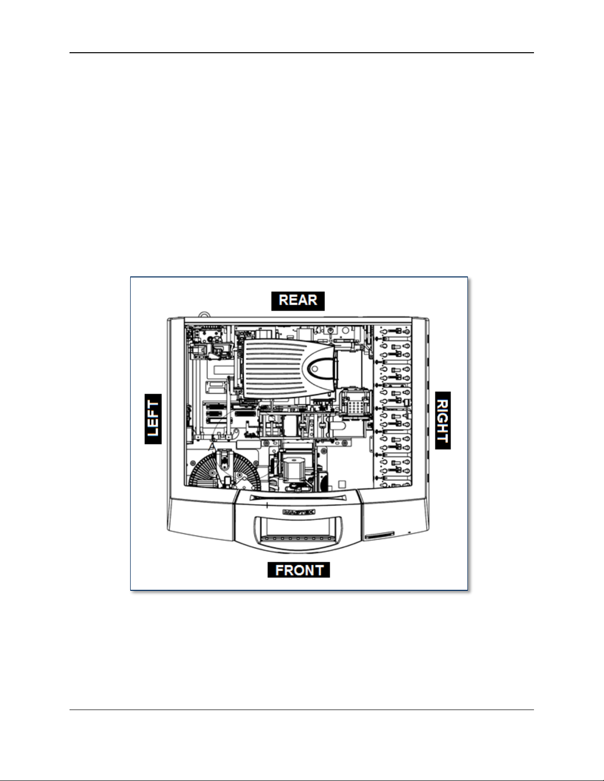
This manual uses the words “Front,” “Rear,” “Left,” and “Right” to describe where to find various parts
of the device. These terms assume the reader is standing in front of the device facing the touchscreen,
and are shown in Figure 2-1. During service, it is normal to move around the device to get easier access
to parts. In the same way, many of the photos and drawings in this manual show the device from different
angles that make key “landmarks” visible. In these cases, the caption will generally state the direction the
figure can be seen from (for example, “FRONT RIGHT VIEW”).
Figure 2-1 – Front/Rear/Left/Right Definition (TOP VIEW)
2.5 Device Specifications
For Electrical, Acoustical, Environmental, Communication, Physical, Encoding, and other detailed
specifications of the EC2000, see 99875600 EC2000 User Installation and Operation Manual.
ExpressCard 2000| Instant Issuance Card Personalization System | Hardware Service Manual
Page 10
Page 11
2 - Introduction
2.6 About Installation & Operation
For detailed instructions about planning, installation, operation, and basic maintenance, see 99875600
EC2000 User Installation and Operation Manual.
2.7 How to Open the Top Access Door
For instructions to open the top access door, see 99875600 EC2000 User Installation and Operation
Manual.
Some procedures require removing the top access door completely. For removal instructions, see section
4.2 How to Remove / Re-install the Top Access Door.
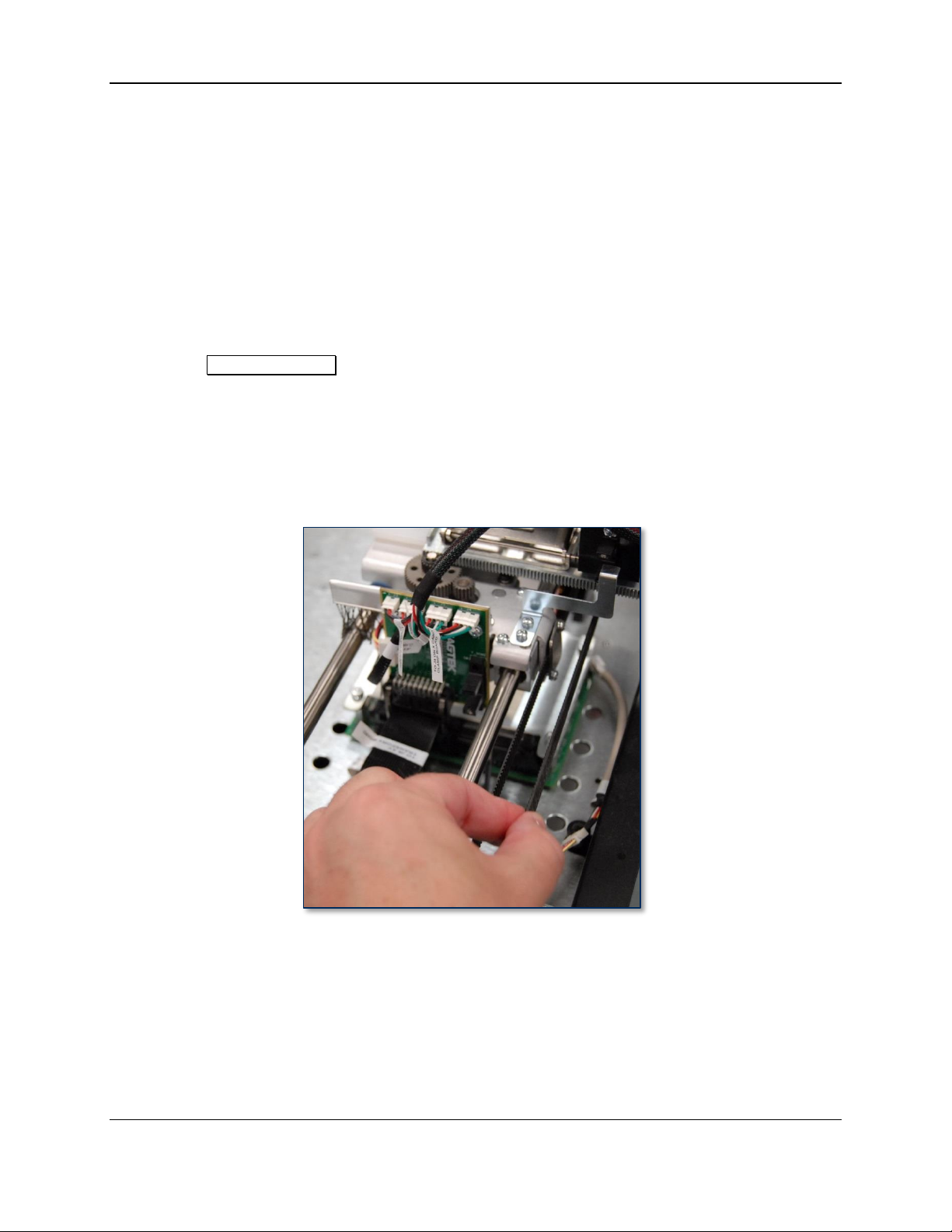
2.8 How to Safely Move Transports By Hand
Although the MCP Commands page is the safest way to move parts within the EC2000 (see section
2.9.1 How to Use the MCP Commands Page), occasionally it is necessary to move parts by hand. To
prevent injury or damage to the device, follow these guidelines:
If you need to move the hopper transport or XY transport by hand, pull only on their serrated drive
belts as shown in Figure 2-2. This reduces the risk of damaging the transport.
If you need to move the XY transport along its tracks, gently pull the carriage to the left side of the
device before moving so it won’t catch on the image printer.
Figure 2-2 - Move Transports By Pulling Drive Belts
You can rotate the rollers on all transports by hand to push/pull cards to where they can be removed.
If a card is stuck in the hopper transport but has not yet gone into the image printer, one easy way to
remove the card is to remove one or two hoppers next to the hopper transport, then pull on its
triangular belt to move the card toward the hopper deck.
If a hopper transport has moved a card mostly into the image printer but the card has become stuck,
remove the card forward through the image printer (toward the XY transport). Do not try to reverse
cards from the image printer into the hopper transport.
ExpressCard 2000| Instant Issuance Card Personalization System | Hardware Service Manual
Page 11
Page 12
2 - Introduction
Press This Button
Verify This Happens
Pusher Home
Hopper transport’s pusher moves into safe position for move
8 To Hopper
Hopper transport moves to (or stays at) manual feed slot, slot light
flashes
7 To Hopper
Hopper transport moves to (or stays at) hopper 1, slot light stops flashing
6 To Hopper
Hopper transport moves to (or stays at) hopper 1
5 To Hopper
Hopper transport moves to (or stays at) hopper 1
To Manual Feed
Hopper transport moves to (or stays at) manual feed slot, slot light
flashes
4 To Hopper
Hopper transport moves to (or stays at) hopper 1
3 To Hopper
Hopper transport moves to (or stays at) hopper 1
Shuttle Home
Hopper transport moves near hopper 1
2.9 How to Use Maintenance Functions On the Touchscreen
This section explains how to use the maintenance functions on the EC2000’s touchscreen. Most of the
functions let you isolate the various subsystems during troubleshooting to determine the failure point, and
to verify repairs have corrected the problem.
To visually inspect the device while it is running, open the top access door and block the sensor mounted
to the rear left of the top access door track. For convenience, 33011008 ASM TOOL KIT,FIELD
SERVICE,EC2000 provides heat shrink tubing that fits snugly over the top access door sensor. Be sure
to put it back in your toolkit before closing the top access door.
To access most maintenance functions of the device using the touchscreen, do the following:
1) Press the Menu button to open the Main Menu page.
2) Press the Settings button to open the Settings Menu page. The Settings Menu page provides
access to user and service functions of the device, some of which require a password. If customers
have changed the passwords, request the new passwords from them. Otherwise the passwords will be
the factory defaults provided in the sections below.
3) Additional maintenance functions can be accessed from the Settings Menu page by pressing the
Service button to open the Service Menu page. For example, you can use the Sensor Utility page
to view the status of the EC2000’s sensors, or use the MCP Commands page to move the various
parts of the EC2000 individually rather than as part of a standard sequence.
2.9.1 How to Use the MCP Commands Page
The move the various parts of the EC2000 individually rather than as part of a standard sequence, use the
touchscreen to navigate to Menu > Settings > Service > MCP Commands to open the MCP
Commands page. Note that the MCP Commands page may allow you to make moves that could
damage the device -- think carefully before sending a direct move command!
Table 2.1 provides an MCP Commands sequence that tests most subsystems by moving a card from
hopper 1 to the output bin. You can test by pressing each button in the list and verifying the described
action happens correctly. The gray highlighted lines make up a shorter sequence that does the same thing.
Table 2.1 - Controller Buttons and Corresponding Movements
ExpressCard 2000| Instant Issuance Card Personalization System | Hardware Service Manual
Page 12
Page 13
2 - Introduction
Press This Button
Verify This Happens
2 To Hopper
Hopper transport moves to (or stays at) hopper 1
1 To Hopper
Hopper transport moves to (or stays at) hopper 1
Bot Cartridge Unload,
Indenter Move
Rear (black) indent cartridge moves out of embosser toward rear of
device
Bot Cartridge Load,
Indenter Move
Rear (black) indent cartridge moves back into embosser
Bot Cartridge Home,
Indenter Move
Rear (black) indent cartridge moves back into (or stays in) embosser
Bot Cart to Indent
Loc., Indenter Move
Rear (black) indent cartridge moves between letters on embosser wheel
Bot Ribbon Advance,
Indenter Move
Ribbon in rear (black) indent cartridge advances by about ¼”
Top Cartridge Unload,
Indenter Move
Only if testing EC2000 with Front Indenter installed:
Front (white) indent cartridge moves out of embosser toward rear of
device
Top Cartridge Load,
Indenter Move
Only if testing EC2000 with Front Indenter installed:
Front (white) indent cartridge moves back into embosser
Top Cartridge Home,
Indenter Move
Only if testing EC2000 with Front Indenter installed:
Front (white) indent cartridge moves back into (or stays in) embosser
Top Cart to Indent
Loc., Indenter Move
Only if testing EC2000 with Front Indenter installed:
Front (white) indent cartridge moves between letters on embosser wheel
Top Ribbon Advance,
Indenter Move
Only if testing EC2000 with Front Indenter installed:
Ribbon in front (white) indent cartridge advances by about ¼”
Roller Consume
Hopper transport’s wheels turn for a few seconds
Push To Roller
Hopper transport takes a card from current hopper
Shuttle To Printer
Hopper transport moves to image printer
Roll To Printer
Hopper transport’s wheels turn for a few seconds to feed card into image
printer. Press Printer Eject button to move card through image printer.
XY Home
XY Transport moves to rear left of device
XY Home X
XY Transport’s X carriage moves to the left
XY Home Y
XY Transport’s Y transport moves to the rear of the device
XY To Printer
XY Transport moves to image printer
XY To Printer In
XY Transport’s X carriage moves toward image printer to engage with
card
Unclamp Card
X carriage’s card clamp rotates to unclamped position
Printer Eject
Card at image printer input is ejected to image printer exit
ExpressCard 2000| Instant Issuance Card Personalization System | Hardware Service Manual
Page 13
Page 14
2 - Introduction
Press This Button
Verify This Happens
Clamp Card
X carriage clamps card at printer exit
Embosser Home
Embosser wheel moves to first character on wheel (look for empty tines
next to the tine that is currently between the hammers)
Embosser hammers open completely (not squeezing embosser tines)
Wheel Home
Embosser wheel moves to first character on wheel (look for empty tines
next to the tine that is currently between the hammers)
XY To Embosser
XY Transport moves card out of printer and to embosser
CardHomeXY
XY Transport moves card so its lower left corner is between embosser
tines
XY To Exit
XY Transport moves card to Exit Transport’s input rollers
Unclamp Card
X carriage’s clamp releases the card
Exit Reject
Exit transport raises its bottom roller, rolls for a short period of time.
Ramp fan turns on. Card goes into Card Rejection Bin.
Exit Eject
Exit Transport rolls card to exit ramp, ramp fan turns on briefly.
ExpressCard 2000| Instant Issuance Card Personalization System | Hardware Service Manual
Page 14
Page 15

2 - Introduction
Sensor Name
Function
Printer Exit
Blocked when there is NO card in the image printer exit, and is unblocked when
there is a card in the image printer exit.
X_Home
Blocked when the X carriage on the XY transport is parked at its left edge.
Y_Home
Blocked when the XY transport is parked at the rear of the device.
Card Clamp
Blocked when the card clamp on the XY transport is closed.
Card Home XY
Blocked when the XY transport reaches the front of the device (at the embosser),
regardless of its X position.
Top Cam
Blocked during normal operation and briefly unblocks when the cam that drives
the top embosser hammer reaches specific points in its rotation.
Bottom Cam
Blocked during normal operation and briefly unblocks when the cam that drives
the bottom embosser hammer reaches specific points in its rotation.
2.9.2 How to Use the Sensor Utility Page
To check the real-time status of all EC2000 sensors, use the touchscreen to navigate to Menu > Settings
> Sensors to open the Sensor Utility page. In normal operation with the top access door closed, with
all card stock hoppers inserted, and with the device just powered up and ready to process cards, the
Sensor Utility page should match Figure 2-3.
Figure 2-3 - Sensor Utility Page
To test a sensor, block or unblock it and verify its status changes. Table 2.2 provides descriptions of each
sensor and the cases where it is blocked or unblocked, and Figure 2-4 on page 17 shows where all sensors
are located in the device.
Table 2.2 - EC2000 Sensor Functions
ExpressCard 2000| Instant Issuance Card Personalization System | Hardware Service Manual
Page 15
Page 16

2 - Introduction
Sensor Name
Function
Card Edge
Blocked EITHER when the embosser daisy wheel is turned such that one of the
tines blocks the sensor, OR when a card enters the area between the embosser
wheels.
Wheel Home
Blocked when the small fin on top of the embosser daisy wheel points toward the
front of the device.
Top Case
Blocked when the top access door is closed.
Shuttle
Exception
Blocked when the hopper transport pushes far enough toward the front of the
device that it mechanically rotates to orient with the manual feed slot.
Hopper Exit
Blocked when a card reaches the point where it is fully and safely loaded from a
hopper into the hopper transport.
Eject Xport
Reserved for future use.
Eject Bin
Reserved for future use.
Exit Just Home
Reserved for future use.
RI Home
Blocked when the rear indent cartridge is in the loaded position (toward the front
of the device).
FI Home
Only used on devices that have the optional front indent module installed. Blocked
when the front indent cartridge is in the loaded position (toward the front of the
device).
Hopper Pull
Unblocked when the card puller on the hopper transport moves in to pick up a card.
Shuttle Home
Blocked when the hopper transport is parked at the rear right corner of the device.
Exception Feed
Blocked when a card just enters the manual feed slot.
RI Unload
Blocked when the rear indent cartridge is in the unload position (toward the rear of
the device).
FI Unload
Only used on devices that have the optional front indent module installed. Blocked
when the front indent cartridge is in the unload position (toward the rear of the
device).
MP Card In
Reserved for future use.
Hopper Card In
Reserved for future use.
Hopper1 Empty
- Hopper7
Empty
Unblocked when there is no hopper installed in the specified hopper slot.
Tipper Cam
Blocked when the tipper heating element is in the up/idle position.
Tipper Grip
Blocked when a card just reaches the rollers on the exit ramp.
Tipper Exit
Blocked when a card just reaches the end of the exit ramp.
ExpressCard 2000| Instant Issuance Card Personalization System | Hardware Service Manual
Page 16
Page 17
2 - Introduction
Figure 2-4 - All EC2000 Sensors Shown In Red (FRONT VIEW)
ExpressCard 2000| Instant Issuance Card Personalization System | Hardware Service Manual
Page 17
Page 18
2 - Introduction
2.9.3 How to Use the Embosser Utility Page
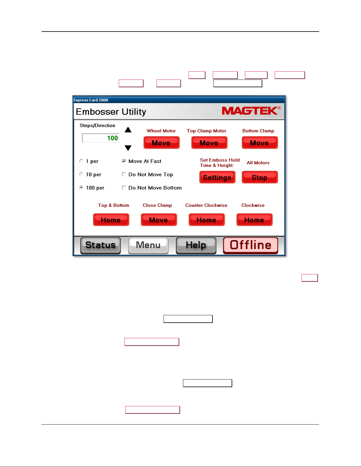
2.9.3.1 About the Embosser Utility Page
To manually move the embosser daisy wheel or hammer cam motors, or to adjust the depth of individual
embossed characters, use the touchscreen to navigate to Menu > Settings > Service > Embosser,
then enter service passwords 4567890 and 0987654 to open the Embosser Utility page.
Figure 2-5 - Embosser Utility Page
The “Steps/Direction” box specifies how many steps the motor will take when you press any of the Move
buttons in the top row. Adjust the “Steps/Direction” value by typing a new value on the keyboard, or by
pressing the up and down arrows. Change how quickly the arrow buttons change the value by selecting
the 1 per, 10 per, or 100 per radio buttons; the default is 100 steps.
The following sections specify how to use the Embosser Utility page to perform specific operations.
2.9.3.2 How to Move the Embosser Daisy Wheel
The daisy wheel, driven by the Wheel Motor Move button, contains the set of characters the embosser
can press into cards. Each character is mounted to one of 80 tines numbered 1 through 80. The motor
takes 20 steps to advance from one tine to the next. To move the daisy wheel a full 360 degrees, move it
(80 characters) x (20 steps per character) = 1600 steps.
To move the daisy wheel, follow these steps from the Embosser Utility page:
1) Turn on the Move At Fast checkbox. The daisy wheel is designed and tested to operate at fast speed.
2) Set the number of steps you want the daisy wheel to take (see section 2.9.3.1 About the Embosser
Utility Page) and press the Wheel Motor Move button.
3) Repeat the moves as necessary to complete the test.
ExpressCard 2000| Instant Issuance Card Personalization System | Hardware Service Manual
Page 18
Page 19

2 - Introduction
4) Re-home the daisy wheel by pressing either the Counter Clockwise Home or Clockwise Home
button. In normal operation, the daisy wheel homes counter-clockwise.
5) Press the All Motors Stop button to make sure the daisy wheel motor is not energized / holding still.
6) Press the Status button to return to the Status page.
2.9.3.3 How to Move the Embosser Cams (Hammers)
The top and bottom embosser cams, which can be driven by the Top Clamp Motor Move button and
Bottom Clamp Motor Move buttons, squeeze the embosser hammers to imprint raised characters on
cards. In a typical emboss cycle, each of the cam motors takes about 600 steps forward to move the cam
from its home position to press into the card, and 600 in reverse to retract back to the home position. One
step is approximately equal to 0.225 degrees of rotation, so the total emboss cycle covers about 135
degrees.
To move the top embosser cam, bottom embosser cam, or both cams, follow these steps from the
Embosser Utility page:
1) Press the All Motors Stop button to make sure no motor is applying force.
2) If there is nothing in the way of the hammers, press the Top & Bottom Home button to make sure
the cams are not closed. The “home” position is the standard starting position for an emboss cycle.
3) Press either the Counter Clockwise Home button or the Clockwise Home button to make sure the
daisy wheel has a character positioned between the embosser hammers. If the daisy wheel is offcenter, the hammers could damage it.
4) You may encounter a situation during testing where you want to close the hammers to their calibrated
close position, but prevent one embosser hammer from moving during testing; for example, to
prevent damage if something is jammed in the device, or if moving a specific cam would be a safety
hazard. In that type of situation, you can prevent one or both of the cams from moving in the next
step by checking the Do Not Move Top and / or Do Not Move Bottom checkbox. Note: This
feature only locks out movement when pressing the Close Clamp button and will not prevent
clamp movement for any other buttons on the page or during normal device operation.
7) Set the number of steps you want the cam(s) to move (see section 2.9.3.1 About the Embosser
Utility Page) and press the Top Clamp Motor Move or Bottom Clamp Move button, OR press the
Close Clamp button, OR press the All Motors Stop button if you find you have moved too far and
need to release the cams immediately.
8) Repeat the moves as necessary to complete the test.
9) Press the Top & Bottom Home button to make sure the cams are not left closed.
10) Press the All Motors Stop button to make sure no motor is applying force.
11) Press the Status button to return to the Status page.
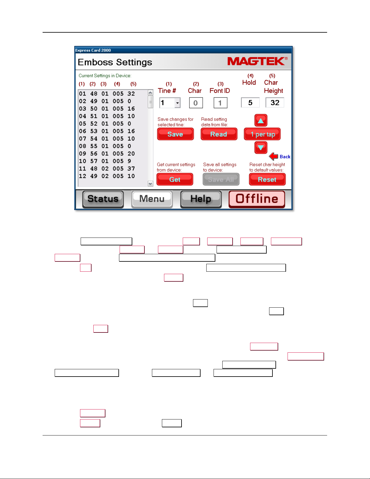
2.9.3.4 How to Change the Embosser Character Depth and Dwell Time
Over time or after embosser service, an individual embossed character’s height may change to the point
that it doesn’t match other characters. The Emboss Settings page provides access to settings for each
tine on the embosser daisy wheel, which affect the pressing force and hold time for that one character.
The Emboss Settings page provides two ways to change these settings: You can import settings for all
tines from a file on the EC2000’s solid state drive or a USB thumb drive using the Read button, or you
can change each tine’s settings individually. The page also provides a Reset button that will reset all
tine settings to factory defaults.
ExpressCard 2000| Instant Issuance Card Personalization System | Hardware Service Manual
Page 19
Page 20
2 - Introduction
Figure 2-6 - Emboss Settings Page
To adjust a single character’s pressing force or hold time, do the following:
1) Open the Emboss Settings page: Navigate to Menu > Settings > Service > Embosser and
enter service passwords 4567890 and 0987654 to open the Embosser Utility page, then press the
Settings button below Set Emboss Hold Time & Height.
2) Press the Get button to refresh the settings shown in the Current Settings in Device list box.
3) Select the tine you want to change in the Tine # drop-down menu. The touchscreen will display the
current settings for that tine in the top row of the page.
4) To adjust how long the embosser hammer will press that specific character into the card before lifting
back off to the embosser home position, change the Hold setting. The setting is in increments of 10
milliseconds, so a value of 5 equals a hold time of 50 ms. In most cases, setting Hold to 0 should
produce acceptable results:
a) Select the Hold field.
b) Enter a new value using the keyboard, or use the up and down arrows to adjust the value. You
can set how quickly the arrows will change the value by pressing the N per tap button.
5) To adjust the depth the hammer will press that specific character into cards, change the Char Height
setting. The EC2000 will add this value to the device’s global EmbossAngleTop and
EmbossAngleBottom settings, or IndentAngleTop and IndentAngleBottom settings, as
appropriate (see section 5.4 How to Calibrate the Embosser). To increase the embossed depth of
that specific character, increase the value; to decrease the embossed depth of a given character,
decrease the value. The valid range is from -127 to +127, but typical values are in the -20 to +40
range.
6) Press the Save All button to save the settings for all tines
7) Press the Status button to return to the Status page.
ExpressCard 2000| Instant Issuance Card Personalization System | Hardware Service Manual
Page 20
Page 21
2 - Introduction
2.9.4 How to Use the Character Mapping Page
The Character Mapping page provides support for changing the configuration of characters on the
EC2000 embosser’s daisy wheel, and will most commonly be used in conjunction with the steps in
section 4.10 How to Remove / Re-install Embosser Fonts and in section 4.11 How to Remove / Re-
install the Embosser. Functions include adding new fonts, moving an existing character to a different
tine, and removing a character from a tine.
At any time (such as if you make a mistake that you discover later in testing), you can reset the changes
you made to the daisy wheel and return them to factory defaults by navigating to Menu > Settings >
Service > Wheel Map and pressing the Reset button.
To move a character from one daisy wheel tine to another, follow these steps:
1) Look at the numbers stamped on each daisy wheel tine to determine which tine the character was (or
is) originally on, and which tine you will move it to.
2) If the character is still on the old tine, uninstall it. Every character has a piece on the top daisy wheel
and a second piece on the bottom daisy wheel, so make sure to uninstall both, and to note which piece
belongs on the top and which piece belongs on the bottom.
3) Install both halves of the character on the new tine.
4) From the touchscreen, navigate to Menu > Settings > Service > Char Map to open the first
Character Mapping password page.
5) Enter password 4567890, then press the E key to open the second Character Mapping password
page.
6) Enter password 0987654, then press the E key to open the Character Mapping page.
7) Use the From Current dropdown list to select the old tine where the character was installed.
8) Use the To New Tine dropdown list to select the new tine where the character is now installed.
9) Press the Move button.
10) Repeat the above steps for any additional characters you need to move.
11) Test your changes by creating a sample card or an embosser tuning card.
To remove a character from a daisy wheel tine, follow these steps:
1) Look at the numbers stamped on each daisy wheel tine to determine which tine you want to remove
the character from.
2) If the character is still on the old tine, uninstall it. Every character has a piece on the top daisy wheel
and a second piece on the bottom daisy wheel, so make sure to uninstall both.
3) From the touchscreen, navigate to Menu > Settings > Service > Char Map to open the first
Character Mapping password page.
4) Enter password 4567890, then press the E key to open the second Character Mapping password
page.
5) Enter password 0987654, then press the E key to open the Character Mapping page.
6) Use the From Current Tine dropdown list to select the tine where the character was installed.
7) Press the Clear button.
8) Repeat the above steps for any additional characters you need to remove.
9) Test your changes by creating a sample card or an embosser tuning card.
To add a new character to a daisy wheel tine, follow these steps:
ExpressCard 2000| Instant Issuance Card Personalization System | Hardware Service Manual
Page 21
Page 22
2 - Introduction
1) Verify the EC2000 software supports the character(s) you are going to install.
2) Look at the numbers stamped on each daisy wheel tine to find the number of the tine where you will
install the new character.
3) Install the character on the tine. Every character has a piece on the top daisy wheel and a second
piece on the bottom daisy wheel, so make sure to install both, and to put each piece on the correct
half: For embossing fonts and rear indent fonts (FontID1, FontID2, and FontID4), the “punch”
(positive) side goes on the bottom; for front indent fonts (FontID3), the “punch” side goes on the top.
Indent fonts have a “blank” flat side that goes opposite the punch side.
4) Install both halves of the character on the new tine.
5) From the touchscreen, navigate to Menu > Settings > Service > Char Map to open the first
Character Mapping password page.
6) Enter password 4567890, then press the E key to open the second Character Mapping password
page.
7) Enter password 0987654, then press the E key to open the Character Mapping page.
8) Use the Add Char. dropdown list to select what character you are installing (for example, if you are
installing a capital ‘A,’ select 65). Verify you have selected the character you expected to select by
looking at the ASCII Char box next to the dropdown list.
9) Use the Font dropdown list to indicate the type of font you have installed (FontID1-4).
10) Use the To dropdown list to select which tine you have installed the characters on.
11) Press the Add button.
12) Repeat the above steps for any additional characters you need to add.
13) Test your changes by creating a sample card or an embosser tuning card.
ExpressCard 2000| Instant Issuance Card Personalization System | Hardware Service Manual
Page 22
Page 23

3 - Preventive Maintenance
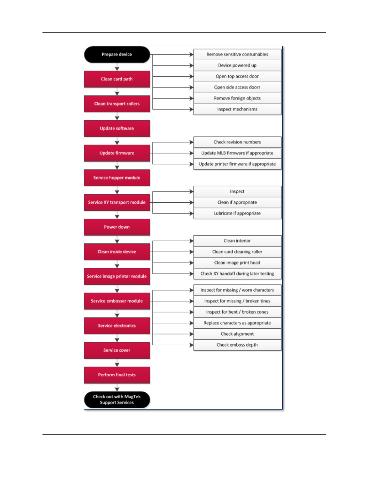
3 Preventive Maintenance
The EC2000 requires regular preventive maintenance to maintain image quality and reliability. Follow
the steps in each section below to perform preventive maintenance.
Before starting, ask the EC2000 user or customer if they have had any specific problems with the device.
If you need to troubleshoot a specific problem, address that before performing preventive maintenance.
See section 6 Diagnosis for assistance troubleshooting reported issues.
The following page shows a flowchart that gives a brief overview of the preventive maintenance
procedure. It should only be used as a guide, not as a substitute for following the detailed steps provided.
ExpressCard 2000| Instant Issuance Card Personalization System | Hardware Service Manual
Page 23
Page 24
3 - Preventive Maintenance
ExpressCard 2000| Instant Issuance Card Personalization System | Hardware Service Manual
Page 24
Page 25
3 - Preventive Maintenance
3.1 Prepare the Device for Preventive Maintenance
To prepare the device for service, follow these steps:
1) Offer the customer the opportunity to remove any proprietary or security-sensitive consumables from
the device, including card stock, image printer ribbons, indent cartridges, and tipper foils. Some
consumables contain negative imprints of cardholder data and must be handled securely.
2) Make sure the device is powered up and connected to the network.
3) Open the top access door (see 99875600 EC2000 User Installation and Operation Manual).
4) Open the two side access doors (see section 4.3 How to Remove / Re-install the Side Access
Doors).
5) Inspect the device for any items that do not belong inside the cover, and remove them (examples
include loose mechanical parts, cards, insect or animal leavings, or jewelry).
6) Inspect the mechanical parts inside the device and inside the image printer, paying special attention to
belts, cables, and plastic gears to see if there are signs of wear or damage.
3.2 Clean the Card Path
Clean the card path per the steps in the Maintenance section of 99875600 EC2000 User Installation
and Operation Manual.
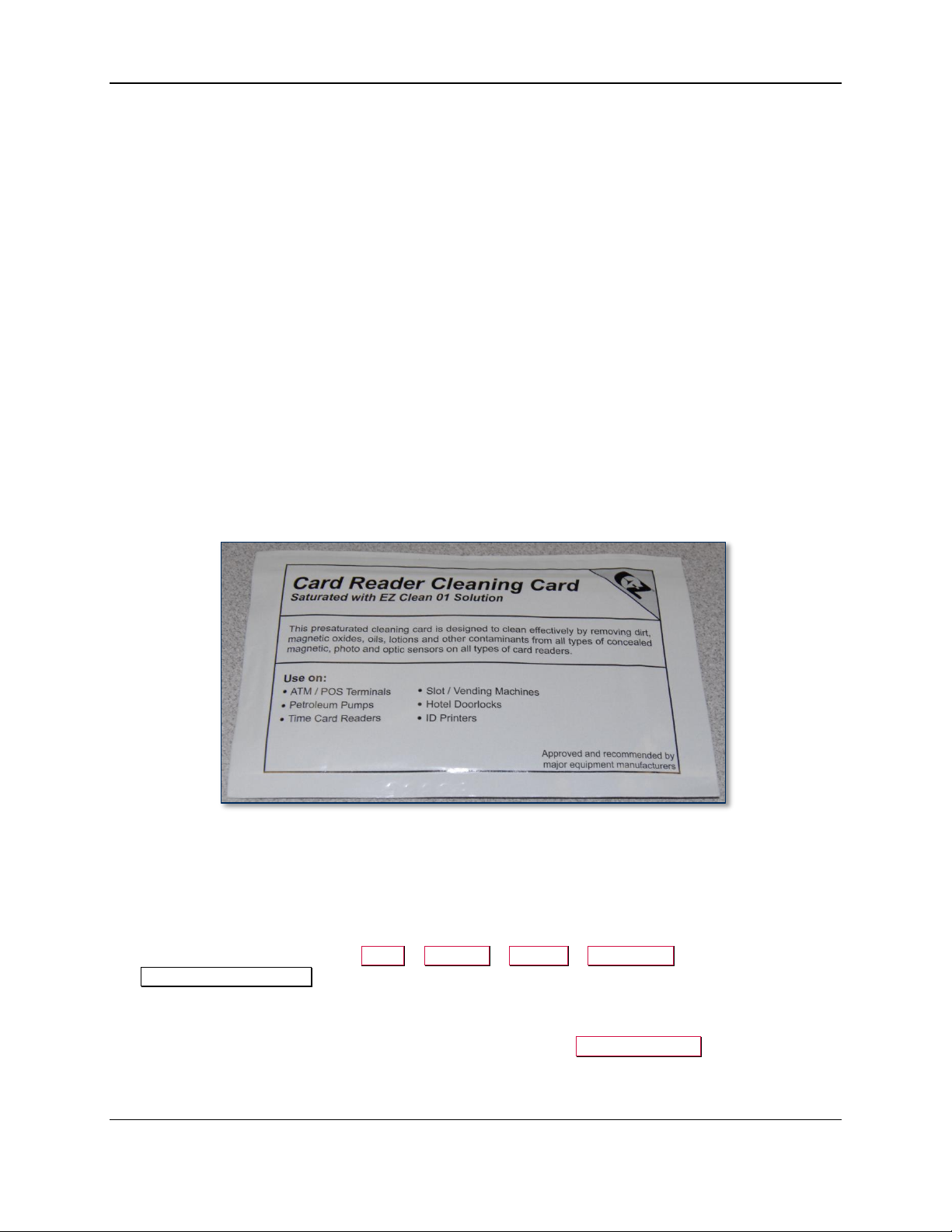
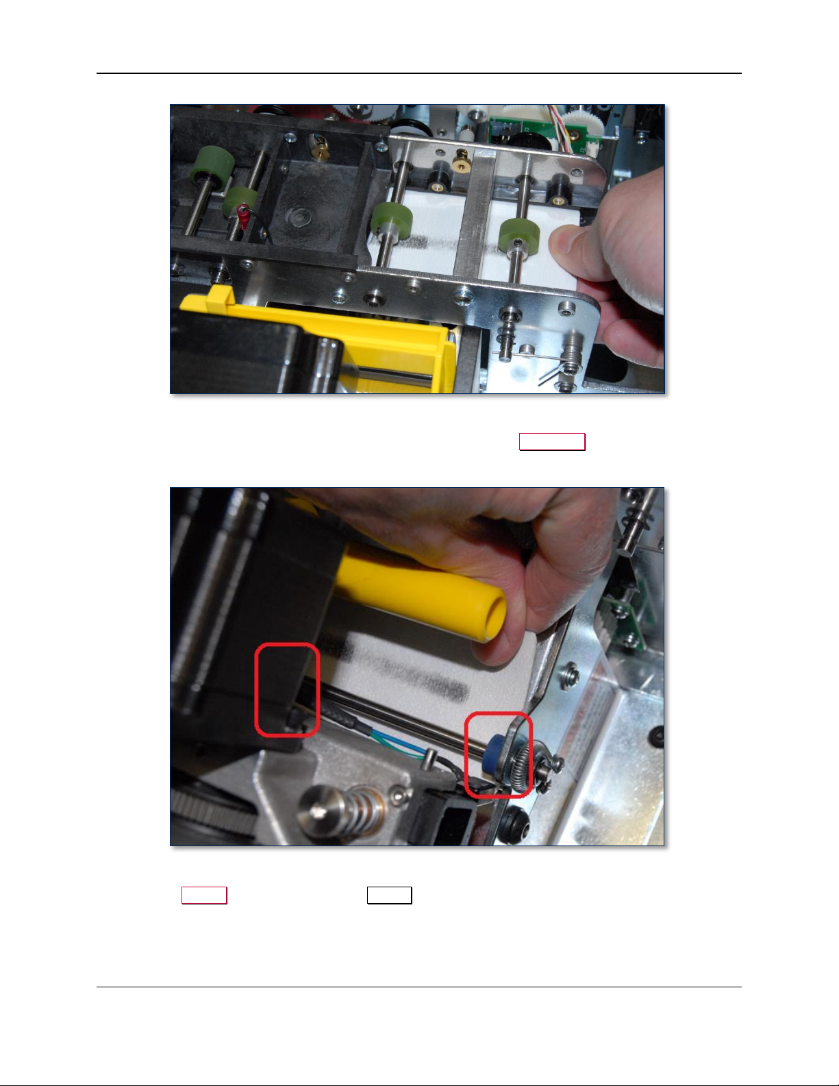
3.3 Clean All Transport Rollers
Follow these steps to clean the rollers on the hopper transport, XY transport, and exit transport. Use the
white cleaning cards:
1) Remove hoppers 1 and 2.
2) Remove the tipper foil cartridge (see 99875600 ExpressCard 2000 User Installation and
Operation Manual for detailed instructions) and set it aside in a secure location, or offer it to the
customer for temporary storage or secure disposal.
3) On the touchscreen, navigate to Menu > Settings > Service > MCP Cmds to open the
Controller Commands page.
4) Use the white cleaning card and do not let the rollers take it out of your hand as you clean each set
of rollers as follows:
a) Feed the card partly into the hopper transport and press the Roller Consume button. Hold the
card there until the rollers stop moving.
ExpressCard 2000| Instant Issuance Card Personalization System | Hardware Service Manual
Page 25
Page 26

3 - Preventive Maintenance
Figure 3-1 - Cleaning the Hopper Transport Rollers (TOP VIEW FROM FRONT)
b) Feed the card partly into the left side of the exit transport and press the Exit Eject button. Hold
the card there until the rollers stop moving.
Figure 3-2 - Cleaning the Left Side of the Exit Transport (TOP VIEW FROM FRONT)
c) Feed the card partly into the right side of the exit transport and press the Exit Reject button.
Push inward to keep the card from being pushed out until the rollers stop moving.
ExpressCard 2000| Instant Issuance Card Personalization System | Hardware Service Manual
Page 26
Page 27
3 - Preventive Maintenance
Figure 3-3 - Cleaning the Right Side of the Exit Transport (TOP VIEW FROM FRONT)
d) Feed the card partly under the exit ramp rollers and press the Exit Eject button. Hold the card
there until the rollers stop moving.
Figure 3-4 - Cleaning the Exit Ramp Rollers (TOP VIEW FROM FRONT)
5) Press the Status button to return to the Status page.
6) Re-install the tipper foil spool assembly with the original tipper foil roll, or obtain and install a new
one from the customer.
7) Re-install hoppers 1 and 2.
ExpressCard 2000| Instant Issuance Card Personalization System | Hardware Service Manual
Page 27
Page 28
3 - Preventive Maintenance
3.4 Update the Software
If MagTek Support Services has supplied .CAB files to apply EC2000 software patches, follow these
steps to install them:
1) Use the Ethernet cable to connect the service laptop to the EC2000. If necessary, you may instead
use the customer’s instant issuance workstation, provided it has Microsoft Internet Explorer and a
USB port with security settings that allow you to read from the USB thumb drive.
2) Launch the Internet Explorer web browser and navigate to https://ec-xxxxxxx, where xxxxxxx is the
device’s serial number. The browser should show an ExpressCard 2000 web interface page.
3) Open the Software Upload link on the left side of the page to display a File to Upload page.
4) Press the Browse… button to launch the Choose File to Upload dialog box.
5) Navigate to the folder that contains the .CAB files you want to apply (such as the field service
laptop’s hard drive or the USB thumb drive).
6) Select the .CAB file you want to apply, and press the Open button to return to the File to Upload
page.
7) Press the Send button to upload the .CAB file to the device. The browser will display a status
message telling you when the patch will be applied (for example, “File Copied Successfully. Update
will be performed during next reboot.”). The device’s touchscreen may also go blank.
8) Restart the device by powering it off, then powering it on. Wait until the touchscreen once again
displays the ExpressCard 2000 Status page.
9) In the web browser, open the Upload Status link on the left side of the page. If the browser reports
“SUCCESS,” repeat these steps for any additional patch .CAB files you need to apply, or continue to
the next section.
ExpressCard 2000| Instant Issuance Card Personalization System | Hardware Service Manual
Page 28
Page 29
3 - Preventive Maintenance
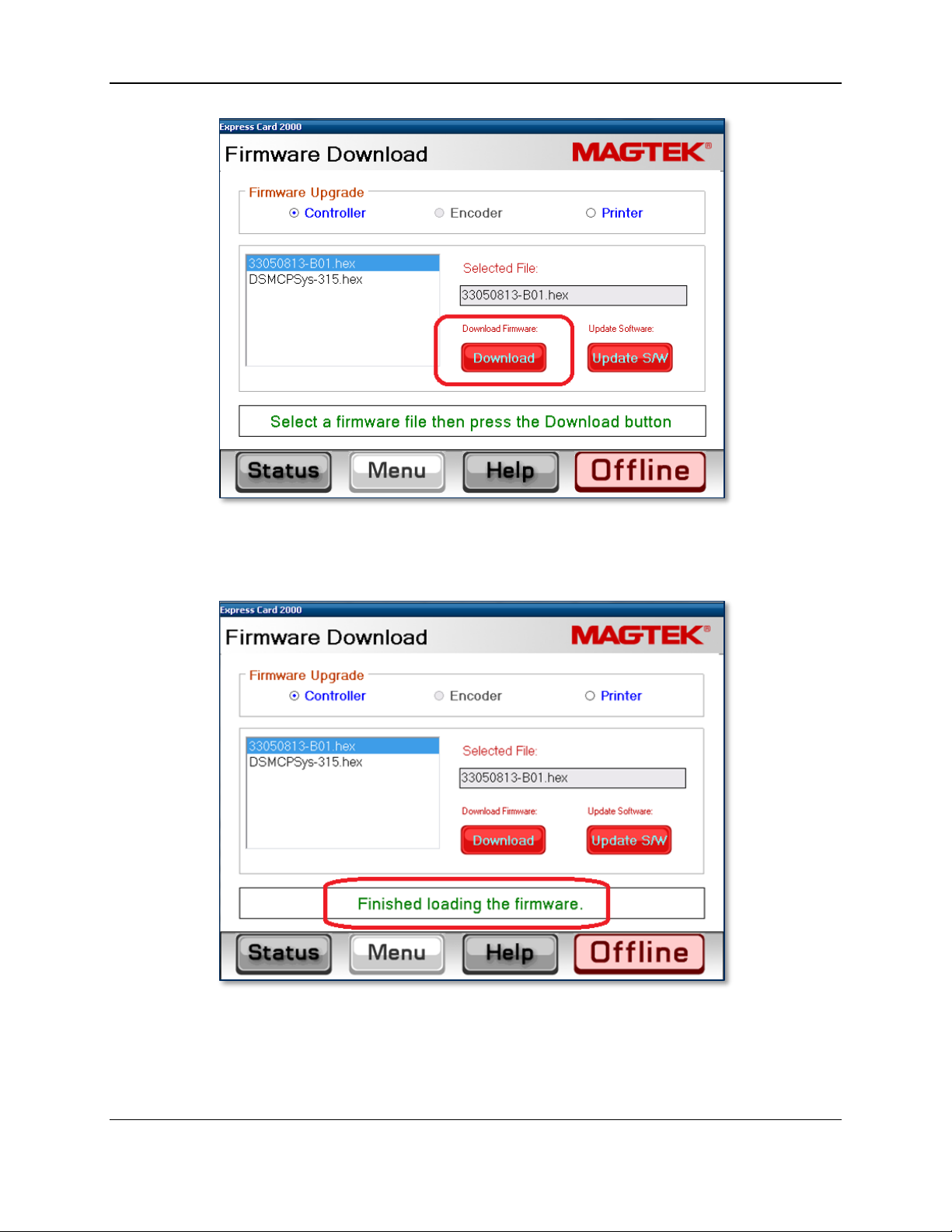
3.5 Update the Firmware
Follow the steps in this section to determine whether the EC2000 firmware needs to be updated, and to
update it if necessary.
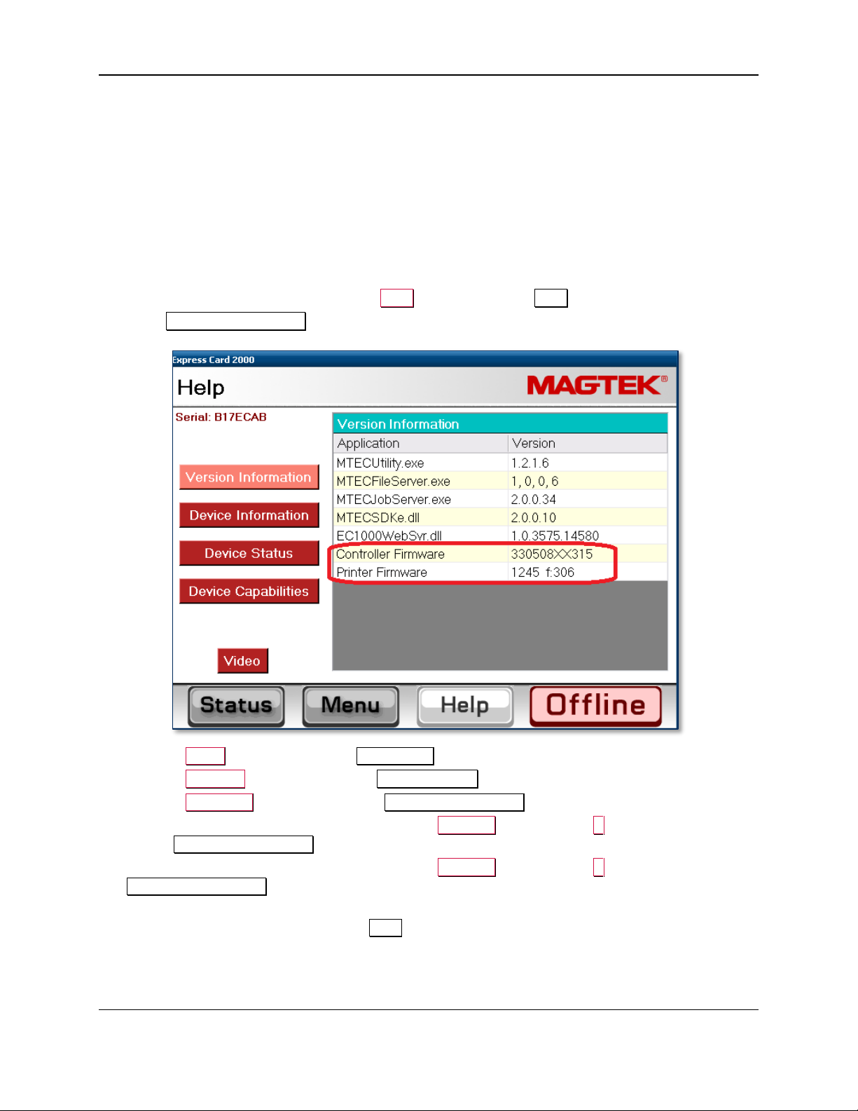
3.5.1 Check Firmware Revision Numbers
To check whether the EC2000 has the latest main logic board (MLB) and image printer firmware
installed, follow these steps:
1) Install any software updates MagTek Support Services has provided, using the instructions in section
3.4 Update the Software. This is a very important first step, because new revisions of firmware files
are distributed to the EC2000 via software updates.
2) From the EC2000 touchscreen, press the Help button to open the Help page.
3) In the Version Information list, note the Controller Firmware and Printer Firmware entries.
4) Press the Menu button to launch the Main Menu page.
5) Press the Settings button to launch the Settings Menu page.
6) Press the Load F/W button to launch the Firmware Download password page.
7) Use the on-screen keyboard to enter the password 1234567, then press the E key to launch the
second Firmware Download password page.
8) Use the on-screen keyboard to enter the password 7654321, then press the E key to launch the
Firmware Download page.
9) Note the revision numbers listed for each .hex file in the list. If any revision number does not match
the revision numbers you found on the Help page, update the firmware for that component using the
steps in the following sections.
ExpressCard 2000| Instant Issuance Card Personalization System | Hardware Service Manual
Page 29
Page 30
3 - Preventive Maintenance
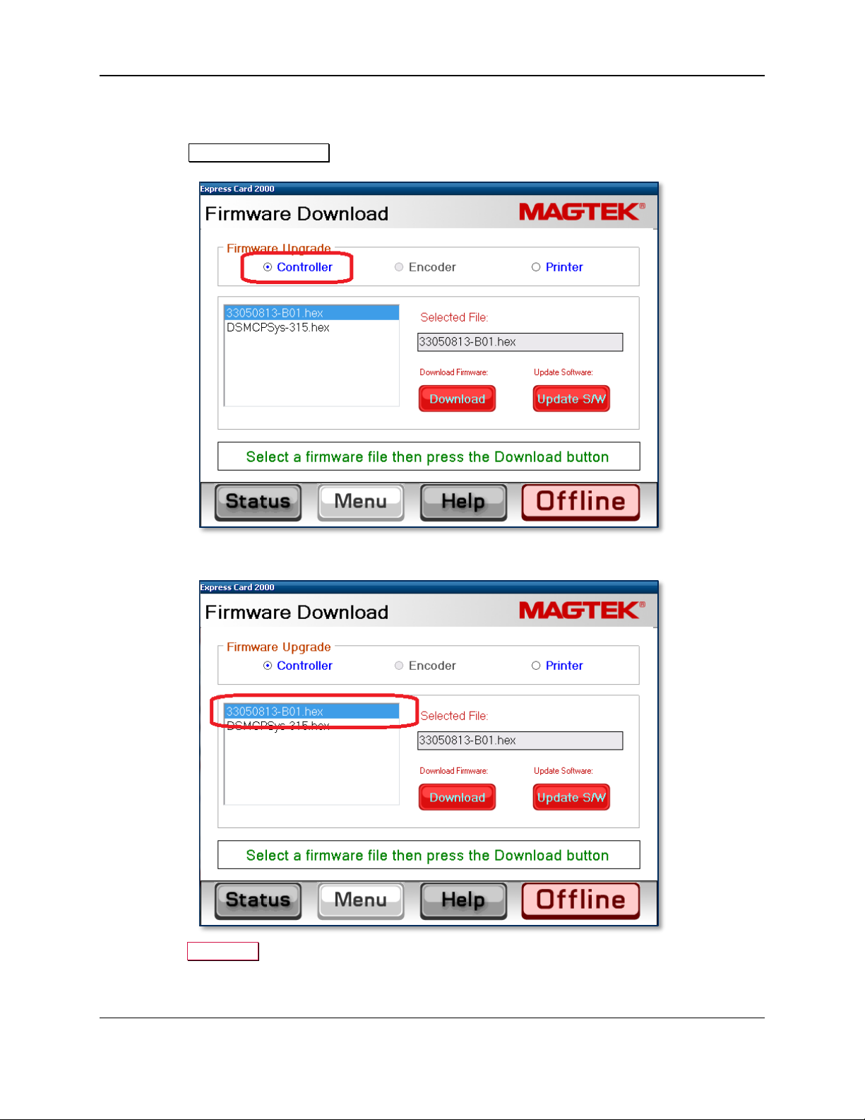
3.5.2 Update the Main Logic Board (Controller) Firmware
To update the controller (main logic board / MLB) firmware, follow these steps:
1) From the Firmware Download page, select the Controller radio button.
2) In the list of .hex files, select the file that corresponds to the new revision.
3) Press the Download button to download the .hex file to the controller. The system will report
“Loading the firmware. Please wait….”
ExpressCard 2000| Instant Issuance Card Personalization System | Hardware Service Manual
Page 30
Page 31
3 - Preventive Maintenance
4) Wait about 5 minutes for the firmware to finish downloading. Do not power off the device.
5) After the firmware update is complete, the device will make sounds as the MLB resets. Wait until the
sounds stop and the touchscreen reports “Finished loading the firmware.”
ExpressCard 2000| Instant Issuance Card Personalization System | Hardware Service Manual
Page 31
Page 32

3 - Preventive Maintenance
3.5.3 Update the Printer Firmware
To update the printer firmware, follow the steps from section 3.5.2, but select the Printer radio button
and select the .hex file appropriate to the revision of the image printer firmware you want to install, before
pressing the Download button.
ExpressCard 2000| Instant Issuance Card Personalization System | Hardware Service Manual
Page 32
Page 33

3 - Preventive Maintenance
3.6 Service the Hopper Module
Follow these steps to service the hopper transport:
1) Use the MCP Commands page (see section 2.9 How to Use Maintenance Functions On the
Touchscreen) to move the hopper transport from the front to the rear of the device to verify the
movement is smooth and there is no belt slippage.
2) Only if the hopper transport rods are dirty, wipe off the dirt with a soft, lint-free cloth.
3) Check the hopper transport drive belt for signs of damage. If it is damaged, contact MagTek Support
Services for a replacement.
ExpressCard 2000| Instant Issuance Card Personalization System | Hardware Service Manual
Page 33
Page 34
3 - Preventive Maintenance
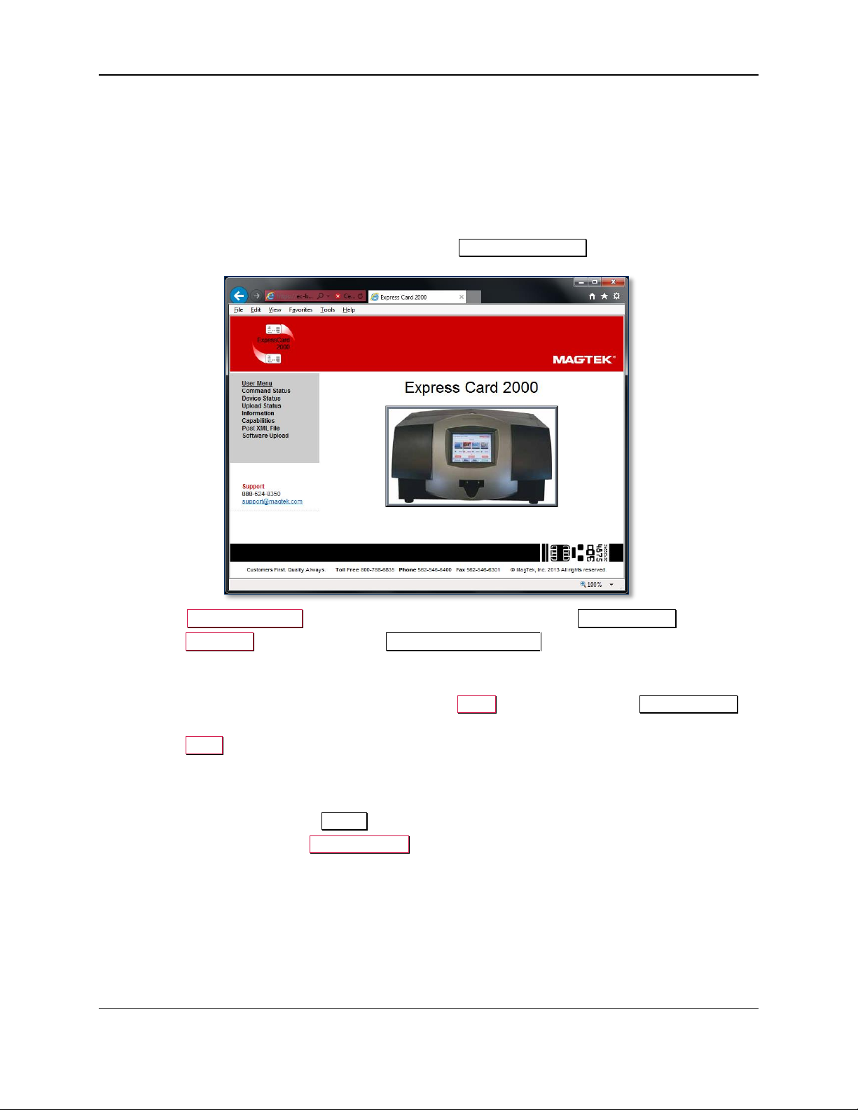
3.7 Service the XY Transport Module
Do not lubricate the EC2000’s gears or bearings. They are made of self-lubricating powder
metal, and lubricants can damage their surfaces.
Follow these steps to lubricate the one shaft that requires lubrication. Do not use Tri-Flow lubricant on
any shaft other than the one shown below.
1) If there is dirt, dust, or debris on the XY transport rods, wipe it off using a soft, lint-free cloth.
2) Use the MCP Commands page (see section 2.9.1 How to Use the MCP Commands Page) to move
the XY transport from the front to the rear of the device to verify the movement is smooth and there is
no belt slippage. Leave the transport at the rear of the device.
3) Check the XY transport drive belt for any signs of damage. If it is damaged, contact MagTek Support
Services for a replacement.
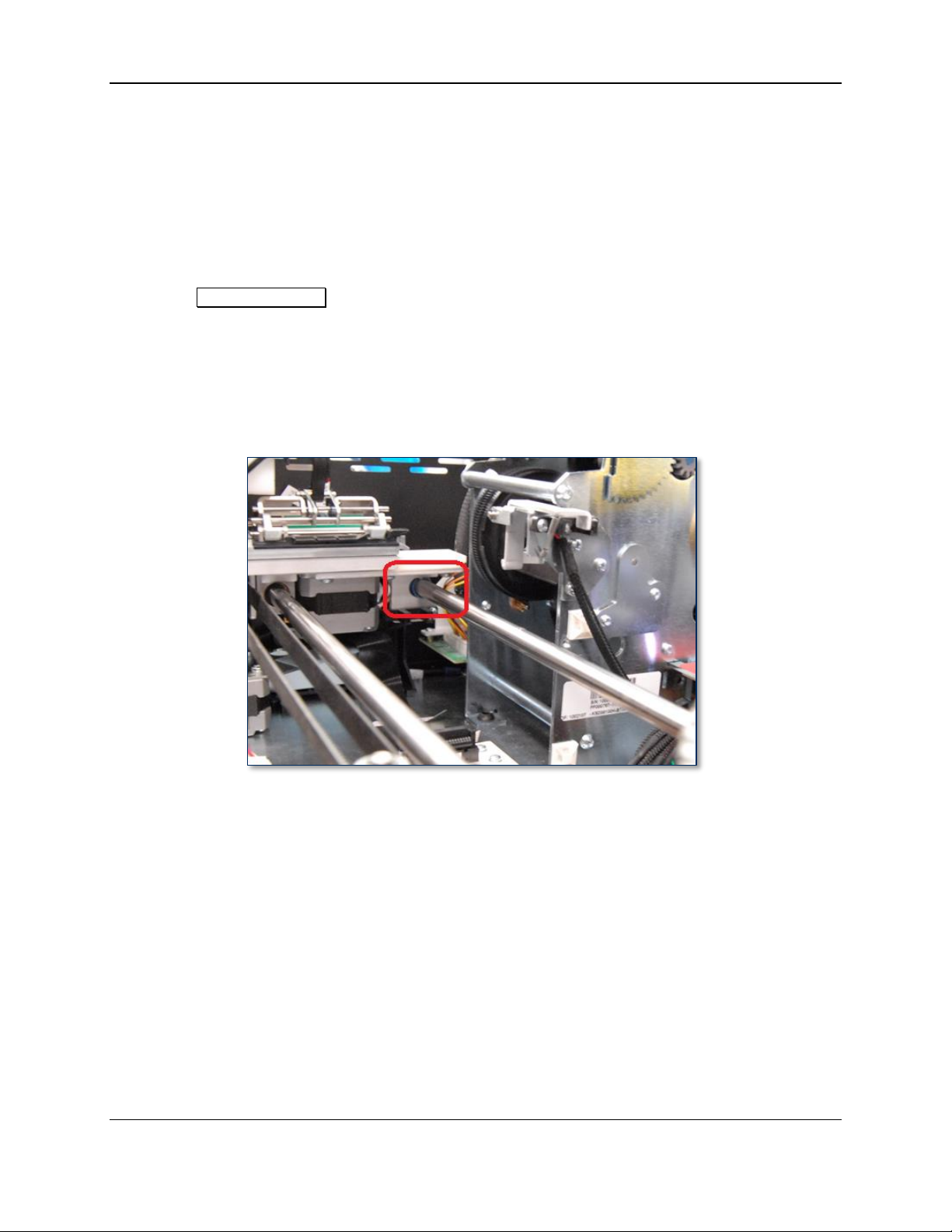
4) Stand at the front of the device and locate the XY transport shaft closest to the image printer. It is the
only shaft that has a blue bearing around it (see Figure 3-5).
Figure 3-5 - Blue Bearing On XY Transport (FRONT LEFT VIEW)
5) Shake the bottle of Tri-Flow lubricant and remove the cap.
6) Run a thin 3-4 inch long bead of Tri-Flow along the top of that one shaft.
ExpressCard 2000| Instant Issuance Card Personalization System | Hardware Service Manual
Page 34
Page 35

3 - Preventive Maintenance
Figure 3-6 - Run a Thin Bead of Tri-Flow Along the Top of the Shaft (TOP LEFT VIEW)
7) Use the drive belt to move the XY transport to the front of the device, then to the rear again to spread
the Tri-Flow along the length of the shaft (see section 2.8 How to Safely Move Transports By
Hand).
8) If you have applied too much Tri-Flow to the shaft, some may drip off the shaft. If this happens, dab
off the excess with a clean, lint free cloth.
ExpressCard 2000| Instant Issuance Card Personalization System | Hardware Service Manual
Page 35
Page 36

3 - Preventive Maintenance
3.8 Service the Exit Transport Module
No additional service is necessary for the Exit Transport, other than the roller cleaning described in
section 3.3 Clean All Transport Rollers.
3.9 Cool the Tipper Heater / Power Down the Device
1) Navigate to Menu > Settings > Tipper to open the Tipper page.
2) Press the Set Heater OFF button to turn off the tipper heater.
3) Note the value under Current Tipper Temp. If the tipper temperature is 50°C or hotter, the tipper
heater is not safe to touch.
4) Take note of the current time, and plan your work to allow enough time for the tipper heater to cool,
which can take up to 15 minutes. You may be able to use compressed air to cool it more quickly.
5) Power down the device.
ExpressCard 2000| Instant Issuance Card Personalization System | Hardware Service Manual
Page 36
Page 37

3 - Preventive Maintenance
3.10 Clean Inside the Device
Caution: Do not use alcohol wipes, liquids, or chemicals on the touchscreen.
Clean the device in phases to avoid blowing dirt, dust, or debris into sensitive components:
1) Remove all remaining consumables from the device (stock cards, image printer ribbon, indent
cartridge[s], tipper foil, etc.) and set them aside in a secure location or give them to the customer for
temporary storage or secure disposal.
2) If there is a large, visible amount of dirt, dust, or debris in the device, wipe the worst of it out with a
clean, dry cloth.
3) Wipe remaining dirt, dust, and debris off the base plate and main components with alcohol wipes.
4) Used compressed air to blow out any remaining dirt, dust, or debris from between components and re-
wipe as necessary.
5) Use compressed air to clean each of the sensors (see section 2.9.2 How to Use the Sensor Utility
Page for an inventory of all sensors in the device).
6) Use compressed air to clean out the electronics in the bottom between the side access doors, with
special attention paid to the power supply in the rear left corner.
ExpressCard 2000| Instant Issuance Card Personalization System | Hardware Service Manual
Page 37
Page 38

3 - Preventive Maintenance
3.11 Service the Image Printer Module
Follow these steps to service the image printer:
1) Make sure the interior of the EC2000 is clean (see section 3.10 Clean Inside the Device).
Performing image printer maintenance with dirt or debris inside the cover may damage the printer.
2) Open the image printer and clean its interior if necessary. Dust and other particles are attracted to the
image printer ribbon or card stock by static produced during image printing, and can contaminate
image-printed cards, causing spots or speckles.
3) Clean the card cleaning roller and replace it if necessary (see 99875600 ExpressCard 2000 User
Installation and Operation Manual for details).
4) Clean the image print head with head cleaning pen (see 99875600 ExpressCard 2000 User
Installation and Operation Manual for details).
5) Check handoff from image printer to XY transport. Adjust if needed (see section 5.3.2 How to
Calibrate Printer to XY Transport Handoff).
ExpressCard 2000| Instant Issuance Card Personalization System | Hardware Service Manual
Page 38
Page 39
3 - Preventive Maintenance
3.12 Service the Embosser Module
3.12.1 About Servicing the Embosser Module
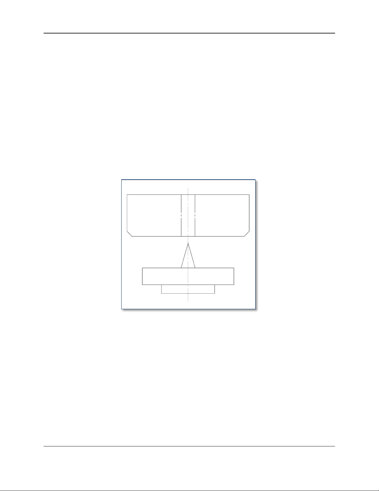
The embosser module presses characters into card stock by squeezing the card between a raised metal
letter, called a punch, and an indented letter of the same shape, called a die, installed on the embosser’s
top and bottom daisy wheels. For indented characters, the die is replaced with a flat metal plate so the
card stock is only altered on the character side. Worn out punches or dies can produce characters of poor
quality, or characters that are raised/indented less than the required depth.
The top and bottom embosser motors each drive a hammer that applies force to the punches and dies on
the daisy wheel. Both hammers have a small round plate with a hole that lines up with a cone on each
character. The cone on each character should be sharp and unbent, and must line up properly with the
hole in the hammer. Figure 3-7 shows a magnified view of a properly aligned hammer (above) and die
(below), viewed from the front of the embosser. Because it can be difficult to see the front of the
embosser module with the EC2000’s cover and other modules installed, it is best to inspect the cones with
an inspection mirror. Section 3.12.2 provides further detail.
Figure 3-7 - Embosser Hammer and Character (FRONT VIEW)
ExpressCard 2000| Instant Issuance Card Personalization System | Hardware Service Manual
Page 39
Page 40

3 - Preventive Maintenance
3.12.2 How to Service the Embosser Module
Service the embosser by following these steps. If you discover any issues you can not resolve, contact
MagTek Support Services to procure a replacement embosser module.
1) Use compressed air to clean the embosser bridge (the metal block between the daisy wheels that
supports the indent cartridge ribbon).
2) Inspect the top and bottom embosser daisy wheels for missing or worn characters and replace them if
possible (see section 4.10 How to Remove / Re-install Embosser Fonts). After installing, make
sure the tine is still intact and holds the character tightly.
3) Inspect the top and bottom embosser daisy wheels for missing, bent, or broken tines. Install any
missing characters on other tines and re-map them after preventive maintenance is complete and the
device is powered up (see section 4.10 How to Remove / Re-install Embosser Fonts and section
2.9.4 How to Use the Character Mapping Page).
4) Inspect the characters on the top embosser wheel to identify any broken or bent cones. Top-side
replacement font sets include:
a) 33070077 FUN TYPE,FARRINGTON F7B,EMBOSS DIE
b) 33070079 FUN TYPE,GOTHIC,ALPHA,EMBOSS DIE,ZERO/OH
c) 33070181 FUN TYPE,GOTHIC,NUMBER,EMBOSS DIE
d) 33070183 FUN TYPE,GOTHIC,SPECIAL CHARACTERS,EMBOSS DIE
e) 33070516 FUN TYPE, FRONT INDENT SANS SERIF, 12PT
f) 33070524 FUN TYPE, INDENT, HELVETICA 8PT
g) 33070546 FUN TYPE, FRONT INDENT SANS SERIF, 14PT
h) 33070581 FUN TYPE, TURKISH EMBOSS DIE
i) 33070075 FUN ANVIL, REAR INDENT.
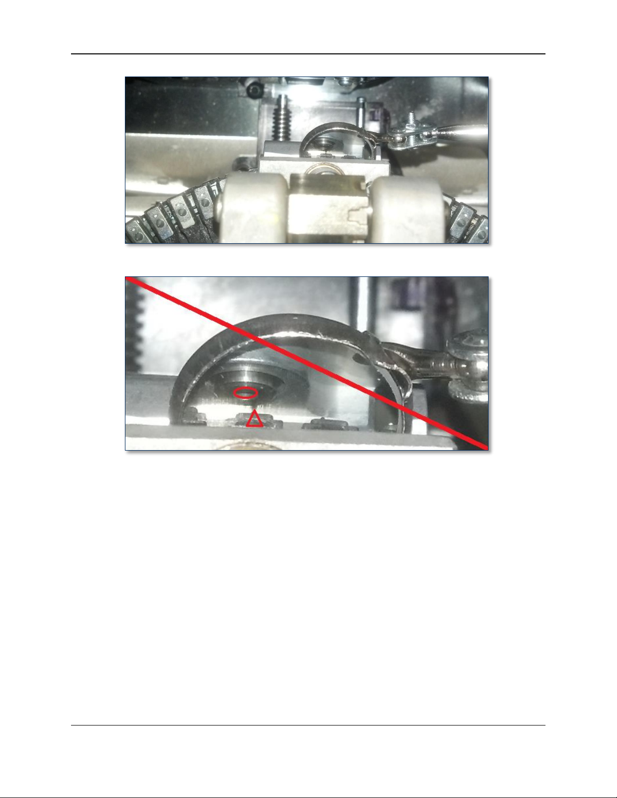
5) Use the inspection mirror and a flashlight to inspect the characters on the bottom embosser wheel to
identify any broken or bent cones (see Figure 3-8 and Figure 3-9). Bottom-side replacement font
sets include:
a) 33070078 FUN TYPE,FARRINGTON F7B,EMBOSS PUNCH
b) 33070080 FUN TYPE,GOTHIC,ALPHA,EMBOSS PUNCH, ZERO/OH
c) 33070081 FUN TYPE,REAR,INDENT,MC,ZERO
d) 33070182 FUN TYPE,GOTHIC,NUMBER,EMBOSS PUNCH
e) 33070184 FUN TYPE,GOTHIC,SPECIAL CHARACTERS,EMBOSS PUNCH
f) 33070582 FUN TYPE, TURKISH EMBOSS PUNCH
g) 33070608 FUN TYPE FRONT INDENT BANK ID NUMBER
h) 33070074 FUN ANVIL,FRONT INDENT
ExpressCard 2000| Instant Issuance Card Personalization System | Hardware Service Manual
Page 40
Page 41
3 - Preventive Maintenance
Figure 3-8 - Using Inspection Mirror to Check Tine / Hammer Alignment (TOP VIEW FROM FRONT)
Figure 3-9 - Bad Embosser Wheel Alignment (Figure 3-8 MAGNIFIED)
6) If any cones are broken or bent, replace the characters in the same location if possible. If replacement
is not feasible, cut off the top and bottom tines using the diagonal side cutters, remove the character
from the tines, and install it to another set of tines, and re-map the character to another tine after
preventive maintenance is complete and the device is powered up (see section 4.10 How to Remove /
Re-install Embosser Fonts and section 2.9.4 How to Use the Character Mapping Page).
7) Check the daisy wheel alignment by standing in front of the device and looking straight down at the
embosser. Use an inspection mirror as shown in Figure 3-8 so you can see the cone on the bottom of
the current character and the hole in the embosser hammer. Figure 3-9 shows a cone and hole that
are not properly aligned.
8) Check embossed character heights using the steps in section 5.4 How to Calibrate the Embosser,
and adjust them if necessary to account for normal wear. Pay special attention to any characters you
have replaced or re-mapped.
ExpressCard 2000| Instant Issuance Card Personalization System | Hardware Service Manual
Page 41
Page 42

3 - Preventive Maintenance
3.13 Service the Electronics
Visually inspect all wires and cables, checking for insulation breakage or wear on moving cables.
3.14 Service the Cover
After completing all other service, service the cover as follows:
1) Inspect the cover for damage.
2) Clean the black and gray portions of the outside of the cover with alcohol wipes.
3) Clean fingerprints off the touchscreen with a soft, clean, dry cloth.
3.15 Perform Final Tests
After completing preventive maintenance, follow these steps to test the device and restore it to its original
state:
1) Re-connect the power and network cables.
2) Re-attach any security hardware.
3) Re-install consumables.
4) Close all open doors.
5) Power up the device.
6) Re-synchronize the image printer ribbon.
7) Create a sample card using customer card stock.
8) Check image print quality and embosser alignment, and adjust components as necessary using the
information in section 5 Adjustments.
9) Fill out the checklist included with the preventive maintenance kit, and return it to MagTek.
ExpressCard 2000| Instant Issuance Card Personalization System | Hardware Service Manual
Page 42
Page 43

4 - Removal and Re-installation
4 Removal and Re-installation
This section describes how to remove and re-install the major assemblies within the EC2000. To avoid
personal injury or damage to the device, be sure to follow ESD procedures (see section 2.3 How to
Handle ESD-Sensitive Parts) and use standard safety practices.
4.1 How to Prepare the Device for Removing / Re-installing Modules
To prepare the device for removing / re-installing modules, follow these steps in accordance with standard
safety practices:
1) Offer the customer the opportunity to remove any proprietary or security-sensitive consumables from
the device, including card stock, image printer ribbons, indent cartridges, and tipper foils. Some
consumables contain negative imprints of cardholder data and must be handled securely.
2) Make sure you have adequate lighting around the device, or plan to use a flashlight.
3) Make sure you have a safe location to place removed parts and replacement parts.
4) If the relevant replacement procedure requires you to use the touchscreen user interface, perform
those steps while the device is still powered up and connected to the network.
5) Power down the device.
6) Disconnect the device’s power cable from the AC socket-outlet, then disconnect the power cable and
network cable from the rear of the device.
7) If necessary, unlock or disconnect any security hardware from the device.
8) If the replacement procedure requires you to remove the device’s top access door or the entire cover,
or requires rear access to the device, make sure you have adequate clearance around the device.
Depending on the installation location, you may need to move the device to a service location.
ExpressCard 2000| Instant Issuance Card Personalization System | Hardware Service Manual
Page 43
Page 44

4 - Removal and Re-installation
Approximate time to remove: 5 minutes plus any sub-procedures
Approximate time to re-install: 5 minutes plus any sub-procedures
4.2 How to Remove / Re-install the Top Access Door
The top access door is the large lockable door in the top of the cover that secures the user-serviceable
areas inside the device, while allowing users to access and replace consumable items like image printer
ribbons and card stock. Some service procedures require removing the top access door to give
unobstructed access to certain components.
Figure 4-1 - Top Access Door (REAR VIEW)
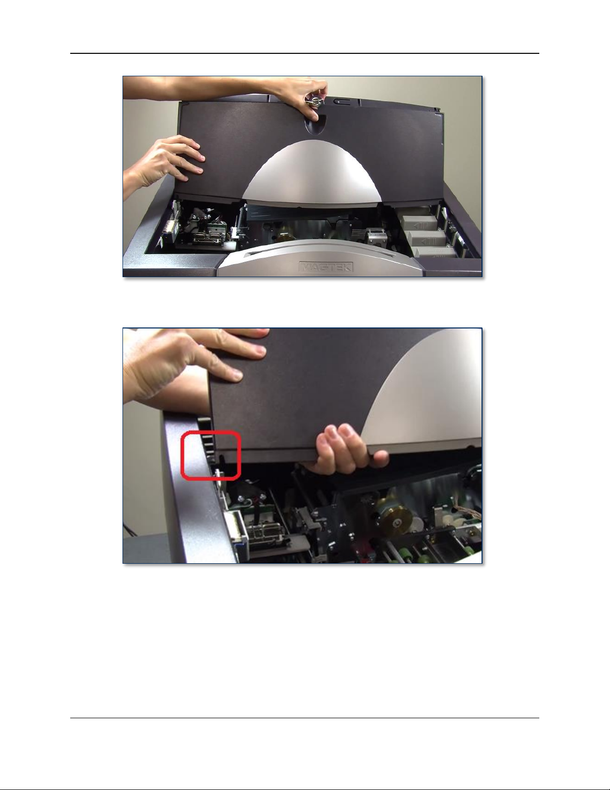
To remove the top access door, follow these steps:
1) Unlock the top access door (see section 2.7 How to Open the Top Access Door).
2) Open the top access door halfway (just past the latches on either side of the cover).
ExpressCard 2000| Instant Issuance Card Personalization System | Hardware Service Manual
Page 44
Page 45
4 - Removal and Re-installation
3) Using both hands, gently pull the top cover to the right, then slightly upward to free it from its left
track as shown in Figure 4-2.
Figure 4-2 - Pulling the Left Side of the Top Access Door Out of Its Track (FRONT VIEW)
4) Repeat the process, pulling it to the left and slightly upward, to free it from its right track.
5) Lean the top access door out toward the rear of the device as shown.
ExpressCard 2000| Instant Issuance Card Personalization System | Hardware Service Manual
Page 45
Page 46
4 - Removal and Re-installation
Figure 4-3 - Top Access Door Leaning Up and Back (FRONT VIEW)
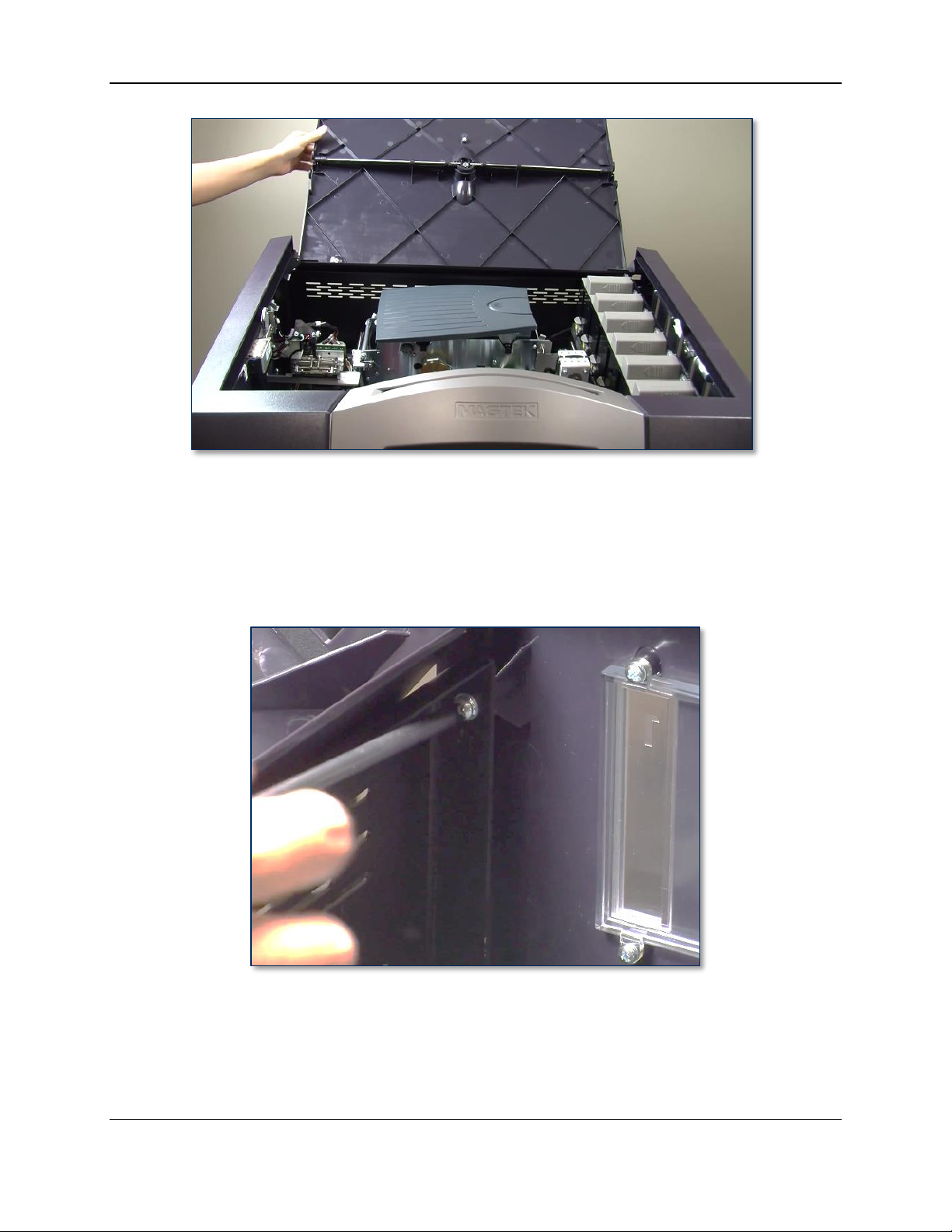
6) Move the hopper transport toward the front of the device, around hopper 6 (see section 2.8 How to
Safely Move Transports By Hand).
7) Remove card stock hoppers 1 and 2.
8) Locate the screw and washer that fasten the cover to the metal plate on the rear of the base. The
fastener can be found in the rear upper right of the device behind hopper 1, as shown in Figure 4-4.
Figure 4-4 - Removing the Right Side Cover Screw Near Top Access Door Hinge (FRONT LEFT VIEW)
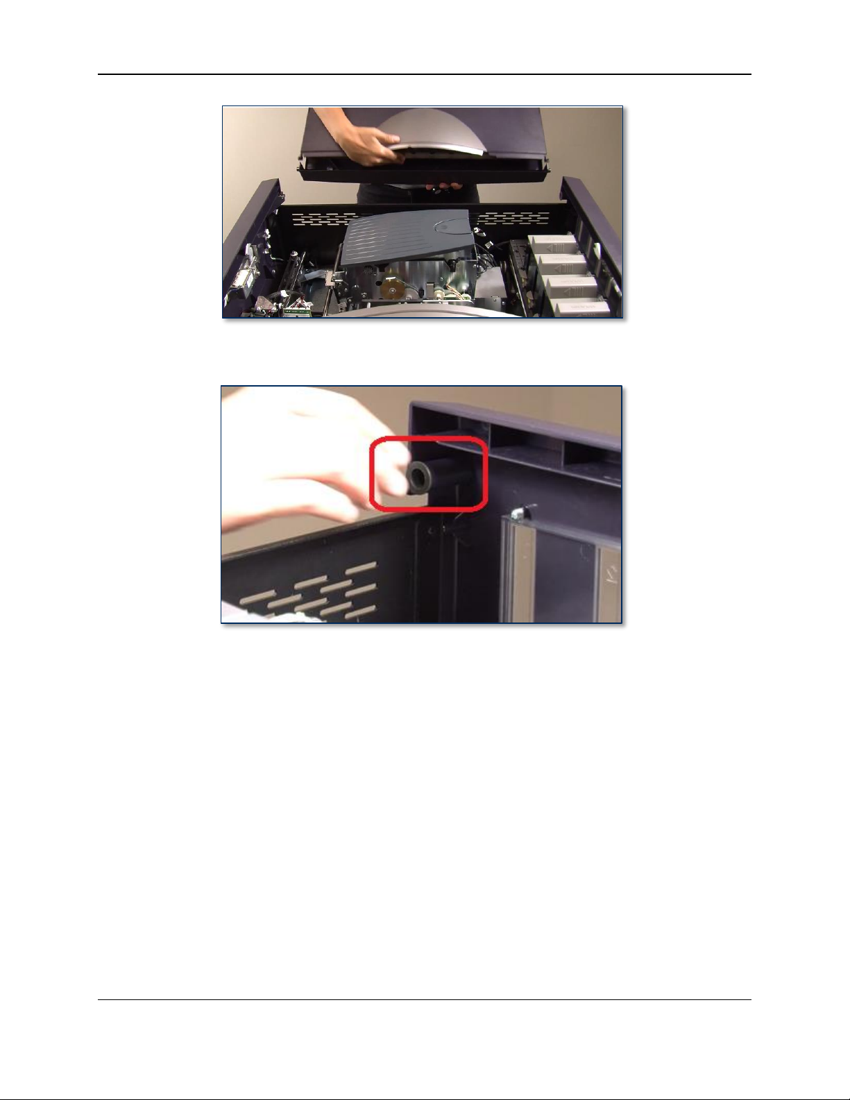
9) During the next step, hold the top access door with one hand or it may fall or break.
10) Use the No. 2 Philips screwdriver to loosen the fastener.
11) Remove the top access door and set it aside with the two screws and washers (if necessary, move the
XY transport out of the way per section 2.8 How to Safely Move Transports By Hand).
ExpressCard 2000| Instant Issuance Card Personalization System | Hardware Service Manual
Page 46
Page 47
4 - Removal and Re-installation
12) Remove the bushings from the top cover’s two hinges (one on each side) and set them aside with the
cover and the two screws and washers.
Figure 4-5 - Top Access Door Hinge Bushings (FRONT LEFT VIEW)
To re-install the top access door, reverse the steps for removing it. Be careful not to lose the door’s
bushings, which are not secured to the cover or to the top access door’s hinges.
ExpressCard 2000| Instant Issuance Card Personalization System | Hardware Service Manual
Page 47
Page 48

4 - Removal and Re-installation
Approximate time to remove: 5 minutes plus any sub-procedures
Approximate time to re-install: 5 minutes plus any sub-procedures
4.3 How to Remove / Re-install the Side Access Doors
The side access doors secure the control electronics (embedded PC, power supply, power controller, and
main logic board) inside the device:
The right side access door gives easy access to the embedded PC’s connectors, including Ethernet
and USB ports (for example, to plug in a keyboard/mouse or USB thumb drive), and also provides
access to examine or replace the Main Logic Board (MLB).
The left side access door provides access to the power supply and the power controller board
(sometimes referred to as the “Green controller”). It is less common to need to open the left side
access door.
Figure 4-6 – Left and Right Side Access Doors (REAR VIEW)
To open the side access doors, follow these steps:
1) Prepare the device for replacing parts by following the steps in section 4.1 How to Prepare the
Device for Removing / Re-installing Modules.
2) Move the hopper transport to the front of the device near the manual feed slot (see section 2.8 How to
Safely Move Transports By Hand). This helps avoid damaging the hopper transport ribbon cable
when removing the right rear thumb screw.
3) If you are removing the left access door, lift the left side of the EC2000 and prop up the two left
rubber feet on a card weight atop a soft cloth or piece of cardboard. Be sure card weights do not stick
out past the rubber feet toward the left edge of the device. Alternatively, you may move the EC2000
to the edge of the work surface so the left side of the device hangs 1” over the edge. This will make it
easier to remove the left access door and will protect the surface you are working on.
Figure 4-7 - Propping Up the EC2000's Feet (LEFT VIEW)
4) Open the top access door (see section 2.7 How to Open the Top Access Door).
5) Using a flashlight, locate the two thumb screws in the base plate on the side you want to open. These
screws lock into holes on the top of the side access door and hold it in place.
ExpressCard 2000| Instant Issuance Card Personalization System | Hardware Service Manual
Page 48
Page 49

4 - Removal and Re-installation
6) Being careful not to pinch any cables or wires between the screwdriver and the screw, use the long
No. 2 Philips screwdriver to unscrew the two thumb screws.
7) Lower the side access door to free its bottom tabs from the cover, remove it, and set it aside (see
Figure 4-8).
Figure 4-8 - Removing the Left Side Access Door (FRONT LEFT VIEW)
To close the side access doors, follow these steps:
1) Orient the side access door straight up and down like it will be on the EC2000 cover.
2) Slide the side access door’s locking tabs into their slots on the bottom of the EC2000’s cover. You
may need to move it forward and back along the cover to find the place where the tabs insert.
3) Hold the side access door up (in place) with one hand.
4) Use the long No. 2 Philips screwdriver to tighten the rear thumb screw.
5) Use the long No. 2 Philips screwdriver to tighten the front thumb screw.
6) Tug on the side access door to make sure it is secure.
7) Remove any props under the device’s feet, and return it to its original location.
ExpressCard 2000| Instant Issuance Card Personalization System | Hardware Service Manual
Page 49
Page 50

4 - Removal and Re-installation
Approximate time to remove: 30 minutes plus any sub-procedures
Approximate time to re-install: 45 minutes plus any sub-procedures
4.4 How to Remove / Re-install the Cover
The EC2000 has a cover which secures the device’s contents and provides mount points for the top access
door and touchscreen, and incorporates the card output hopper and manual feed slot. Some service
procedures require removing the device’s cover to give unobstructed access to certain components.
Figure 4-9 – Cover (REAR LEFT VIEW, REAR RIGHT VIEW)
Follow these steps to remove the cover:
1) Prepare the device for replacing parts by following the steps in section 4.1 How to Prepare the
Device for Removing / Re-installing Modules. At the end, the device should be powered down with
all external cables safely disconnected.
2) Remove the top access door by following the steps in section 4.2 How to Remove / Re-install the
Top Access Door, including safely powering down and disconnecting external cables.
3) Remove the magnetic stripe reader by following the steps in section 4.20 How to Remove / Re-
install the Magnetic Stripe Reader (MSR) Module.
4) Remove all the card stock hoppers from the device and set them aside. Remember to move the
hopper transport out of the way as you remove them (see section 2.8 How to Safely Move
Transports By Hand for more information).
ExpressCard 2000| Instant Issuance Card Personalization System | Hardware Service Manual
Page 50
Page 51

4 - Removal and Re-installation
Figure 4-10 - Removing Card Stock Hoppers (LEFT VIEW)
5) Disconnect the BEZEL LED signal cable from the inside of the manual feed slot.
Figure 4-11 - Bezel LED Signal Cable (REAR VIEW)
6) Disconnect the Exception Card Entry sensor cable in the front right corner of the device.
ExpressCard 2000| Instant Issuance Card Personalization System | Hardware Service Manual
Page 51
Page 52
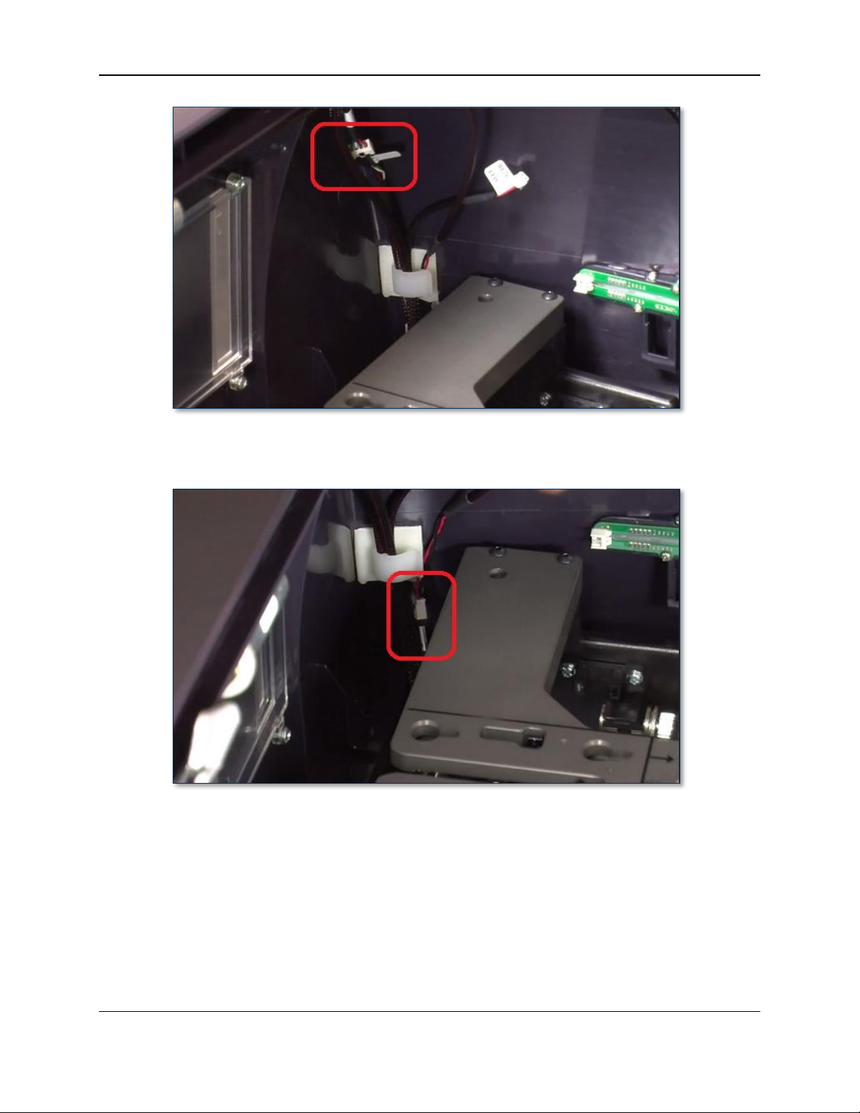
4 - Removal and Re-installation
Figure 4-12 - Exception Card Entry Sensor Cable (REAR VIEW)
7) Disconnect the Door 1 sensor cable in the front right corner of the device.
Figure 4-13 - Door 1 Sensor Cable (REAR VIEW)
8) Disconnect the touchscreen VGA video cable and the power cable from the rear of the touchscreen.
If there is any silicone adhesive on the cables or their connections, remove it completely.
ExpressCard 2000| Instant Issuance Card Personalization System | Hardware Service Manual
Page 52
Page 53

4 - Removal and Re-installation
Figure 4-14 - Touchscreen VGA Cable and Power Cable (REAR VIEW)
9) If there are any cable ties anchoring the touchscreen cables to the cover, use the wire cutters or
diagonal cutters to cut the cable ties, and replace them when re-installing the cover.
Figure 4-15 - Touchscreen Power and VGA Cables (REAR VIEW)
10) Disconnect the Top Case Open sensor cable in the rear left corner of the device.
ExpressCard 2000| Instant Issuance Card Personalization System | Hardware Service Manual
Page 53
Page 54

4 - Removal and Re-installation
Figure 4-16 - Top Case Open Sensor Cable (RIGHT VIEW)
11) Disconnect the Door 2 Solenoid cable connected to the top access door latch on the left side of the
device. Disengage the bottom part of the cable from the clip on the wall of the cover.
Figure 4-17 - Door 2 Solenoid Cable (RIGHT VIEW)
13) Use the No. 2 Philips screwdriver to remove the fastener that secures the cover to the metal plate on
the rear face of the base. It can be found in the upper rear right of the device behind hopper 1, as
shown in Figure 4-17.
ExpressCard 2000| Instant Issuance Card Personalization System | Hardware Service Manual
Page 54
Page 55
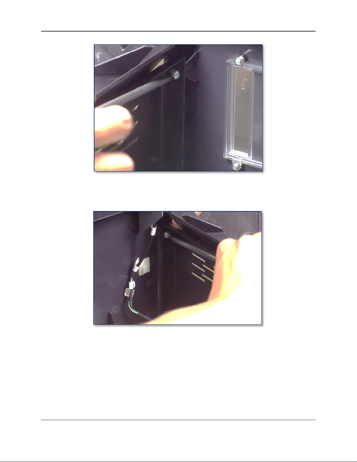
4 - Removal and Re-installation
Figure 4-18 - Removing the Right Side Cover Screw Near Top Access Door Hinge (FRONT LEFT VIEW)
14) Use the No. 2 Philips screwdriver to remove the screw and washer in the rear upper left of the device,
opposite the fastener you have already removed (see Figure 4-20).
Figure 4-19 - Removing the Left Side Cover Screw Near Top Access Door Hinge (FRONT RIGHT VIEW)
12) Locate the eight screws and washers and four plastic plates that clamp the two sides of the cover to
the top deck plate (see Figure 4-9).
13) Use the No. 2 Philips screwdriver to remove the screws, washers, and plates and set them aside.
Note: The front two screws may be easier to remove with the No. 1 Philips screwdriver.
ExpressCard 2000| Instant Issuance Card Personalization System | Hardware Service Manual
Page 55
Page 56

4 - Removal and Re-installation
Figure 4-20 - One of Eight Screws On Sides of Cover (TOP VIEW FROM FRONT)
Figure 4-21 - Plastic Fastener Plates (LEFT VIEW)
14) Locate the two screws that secure the front of the cover next to the tipper.
ExpressCard 2000| Instant Issuance Card Personalization System | Hardware Service Manual
Page 56
Page 57

4 - Removal and Re-installation
Figure 4-22 - Cover Screws Next to Tipper (REAR VIEW)
15) Use the No. 2 Philips screwdriver to remove the screws and set them aside.
16) Pull the silver portion of the cover forward slightly to release it from the device.
17) Carefully remove the cover by pulling it forward a few inches with both hands, making sure there are
no cables tangled with it, then pull it toward the ceiling and set it aside.
Figure 4-23 - Removing the Cover (FRONT LEFT VIEW)
18) Perform any additional replacement or maintenance steps.
ExpressCard 2000| Instant Issuance Card Personalization System | Hardware Service Manual
Page 57
Page 58

4 - Removal and Re-installation
To re-install the cover, follow these steps:
Note: Re-installing the cover is an intricate, detailed procedure that can affect the security
and functionality of the device. Perform each step carefully and methodically, and make
sure everything is in place before proceeding to the next step.
1) Move any loose cables toward the center of the device so they will not be in the way of the cover.
2) Stand in front of the device and use both hands to slide the cover forward until it rests solidly on the
base of the device and does not have to be held in place.
Figure 4-24 - Cover Resting On Top Deck (REAR VIEW)
3) Move the cover slightly to the right and rest its right side on the tabletop next to the device; this will
give you easier access to the connectors around the hopper module.
4) Re-connect the cables you disconnected before removing the cover.
5) Re-tie or re-clip any cables you untied or unclipped before removing the cover.
ExpressCard 2000| Instant Issuance Card Personalization System | Hardware Service Manual
Page 58
Page 59
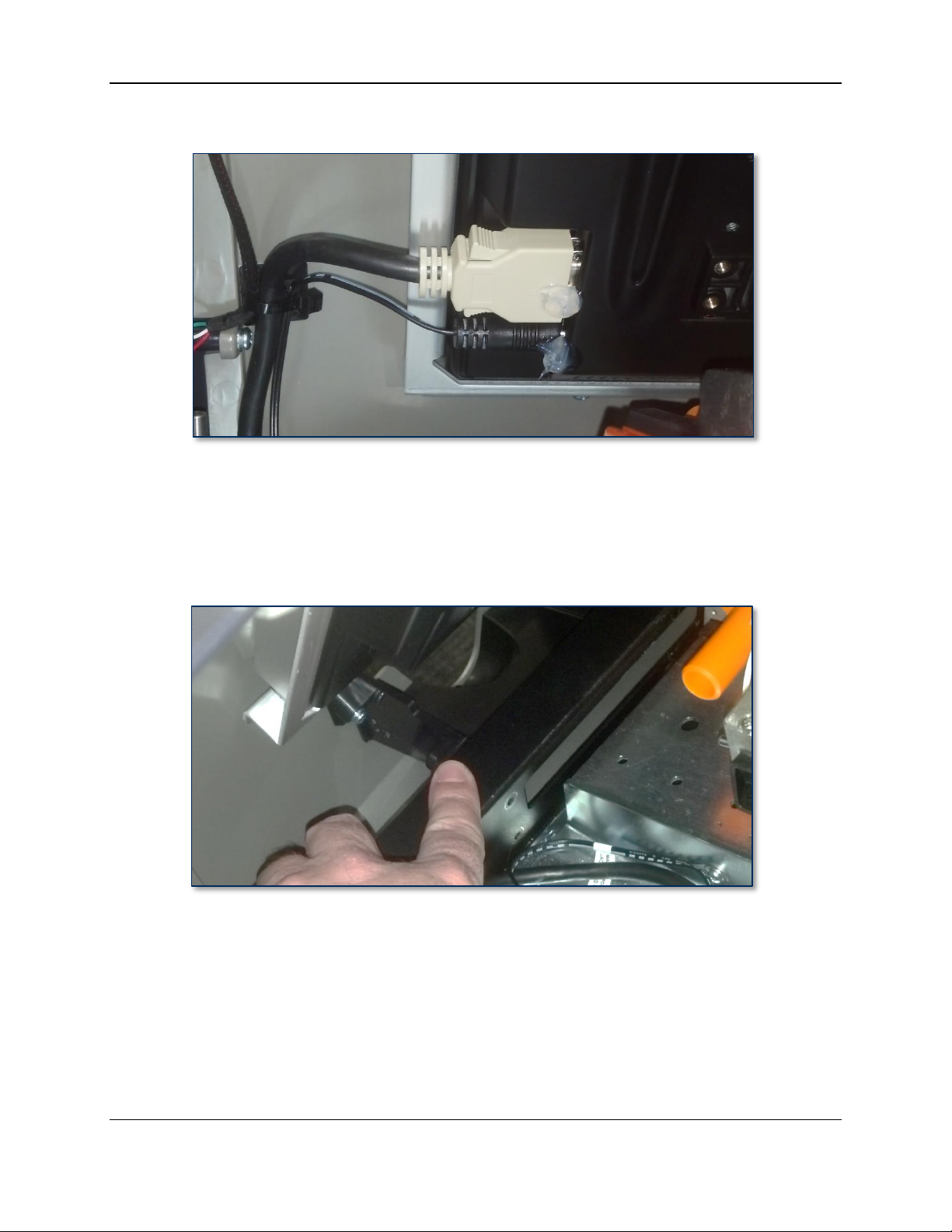
4 - Removal and Re-installation
6) Apply silicone adhesive to secure the touchscreen power and video cables as shown in Figure 4-25.
Figure 4-25 - Silicone Adhesive On Touchscreen Connectors (REAR VIEW)
7) Bring the cover back up to resting squarely on the base as shown in Figure 4-24.
8) Stand in front of the device and look straight down over the front. Locate the extension of the cover’s
card output hopper that will meet up with the end of the exit ramp (see Figure 4-26). Push that
portion of the cover gently toward the floor and slide it slightly toward the rear of the device, just
until the base of the device “captures” it.
Figure 4-26 - Card Output Hopper Touching Device's Base (REAR RIGHT VIEW)
9) Crouch in front of the device. Put a finger on each side of the lowest straight sides of the silver
portion of the cover (see Figure 4-27). Squeeze each side inward carefully, and press toward the rear
of the device until the base of the device “captures” them.
ExpressCard 2000| Instant Issuance Card Personalization System | Hardware Service Manual
Page 59
Page 60
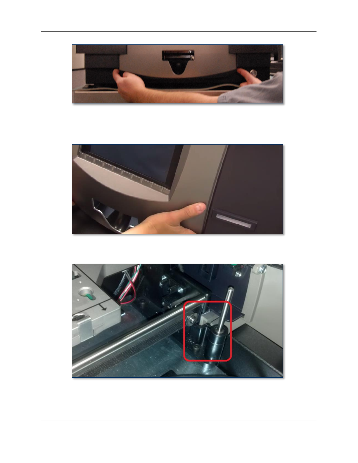
4 - Removal and Re-installation
Figure 4-27 - Fitting the Silver Portion of the Cover (FRONT VIEW)
10) “Bump” the front of the silver portion of the cover (just to the right of the card output hopper) with
the palm of your hand to firmly seat the cover in place.
11) Make sure the silver portion of the cover is solidly seated in the slot in the base, and that the darker
portion of the cover is properly seated above it. See Figure 4-28 for reference.
Figure 4-28 - Silver Portion of Cover Properly Seated (REAR LEFT VIEW)
12) Make sure the two sides of the cover roughly line up with their screw holes. This will align the screw
holes in the front of the cover.
ExpressCard 2000| Instant Issuance Card Personalization System | Hardware Service Manual
Page 60
Page 61

4 - Removal and Re-installation
13) Use your fingers to insert the two screws that fasten the cover to the front of the device (see Figure
4-22), then use the No. 1 Philips screwdriver to loosely screw them into place to constrain the cover
from moving left to right.
14) Loosely screw in the two screws that fasten the cover to the rear plate (see Figure 4-18 and Figure
4-19) to constrain the cover from moving front to rear.
15) Fully insert the eight screws that fasten the cover to the base. Follow these helpful hints:
a) Put a light below the screw holes before attempting to line them up.
b) Use your free hand to push the cover into the right position to insert the screws.
c) It may be helpful to use the magnetic retriever tool to insert them into the holes, then use the
screwdriver or a finger to push them all the way in.
16) One by one, line up each of the plastic fastener plates below their matching screws, hold them in
place, and tighten the screws. The diagonal portion of each fastener plate will be in the midline of the
device as shown. Follow these helpful hints:
a) The easiest tool to tighten the front corner screws is a screwdriver with a heavy-duty flex
extension. If one is not available, they may be easier to tighten using the No. 1 screwdriver
leaned flush against the inside corner of the cover’s top opening.
b) For each plate, fasten the midline screw first, then the corner screw.
c) Look into the cover from above to put the screwdriver firmly into the screw head first, then
crouch next to the device to line up the plate, then tighten the screw partway.
d) Do not push the plates too hard toward the ceiling, or you may pop the screw out of its hole.
e) Screw both screws partway into the plate before tightening them all the way.
Figure 4-29 - Front Left Fastener Plate (LEFT VIEW)
17) Tighten the remaining loose screws EXCEPT the top rear right (you will tighten that after re-
installing the top access door).
18) Re-install the top access door by following the steps in section 4.2 How to Remove / Re-install the
Top Access Door.
19) Complete any other service that requires the device to be powered off and open.
20) Power up the device and test it, paying special attention to the following:
a) Test the touchscreen and manual feed slot light and functionality by creating a sample card from
the manual feed slot using the touchscreen.
b) Make sure the device shows Offline on the Status page when the top access door is open.
c) Test the electronic latches by testing the remote unlock function.
ExpressCard 2000| Instant Issuance Card Personalization System | Hardware Service Manual
Page 61
Page 62

4 - Removal and Re-installation
21) If the EC2000 does not power up or function properly, contact MagTek Support Services for
assistance (see Appendix A Technical Support).
ExpressCard 2000| Instant Issuance Card Personalization System | Hardware Service Manual
Page 62
Page 63
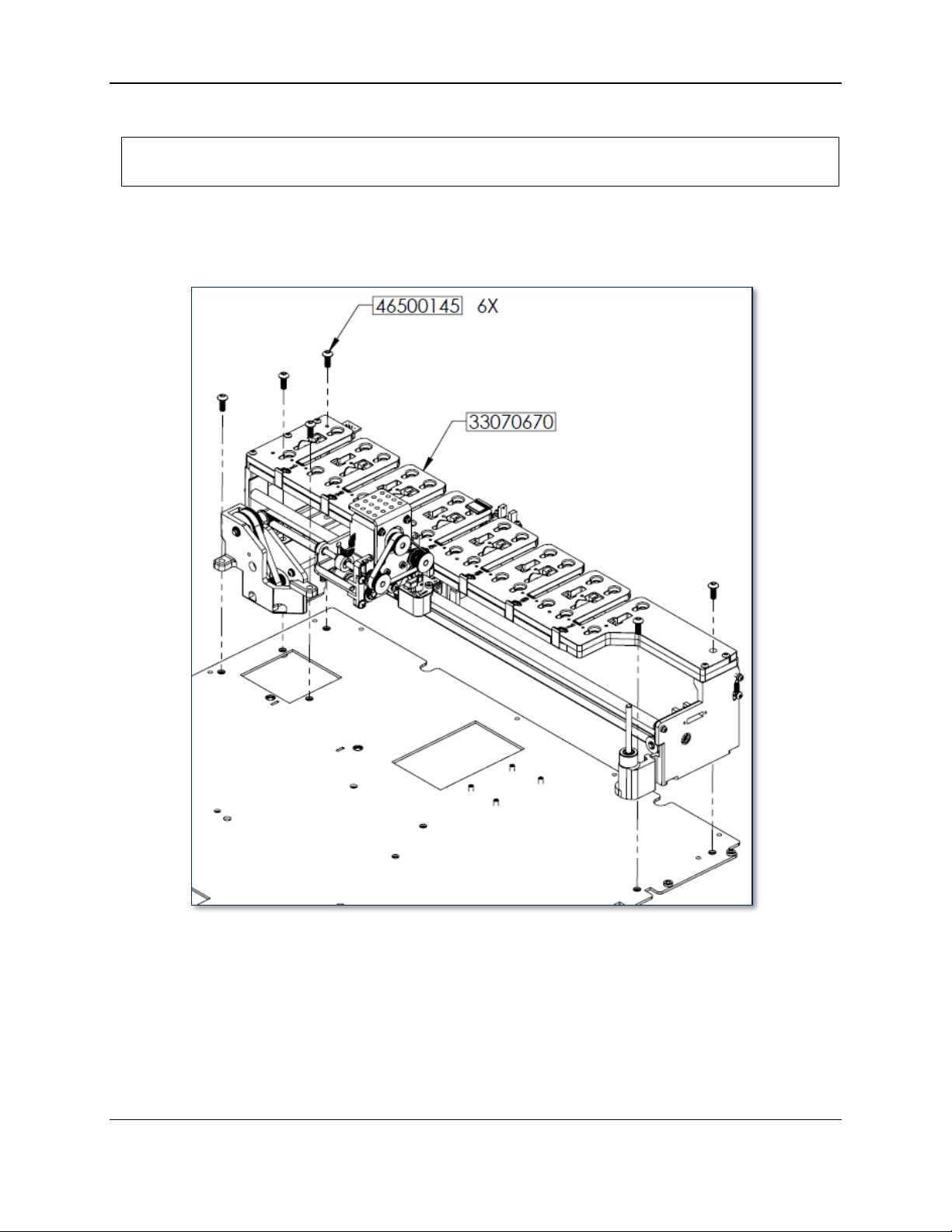
4 - Removal and Re-installation
Approximate time to remove: 30 minutes plus any sub-procedures
Approximate time to re-install: 30 minutes plus any sub-procedures
4.5 How to Remove / Re-install the Hopper Module
The hopper module holds the device’s card stock hoppers and carries blank card stock to the image
printer from the hoppers or from the manual feed slot. It is mounted to the top deck plate of the device
along the right side.
Figure 4-30 - Hopper Module (FRONT LEFT VIEW)
To remove the hopper module, follow these steps:
1) Prepare the device for replacing parts by following the steps in section 4.1 How to Prepare the
Device for Removing / Re-installing Modules. At the end, the device should be powered down with
all external cables safely disconnected.
2) Remove the cover by following the steps in section 4.4 How to Remove / Re-install the Cover.
3) Move the hopper transport to the front of the device, just past hopper 7 and before it rotates to the
manual feed slot (see Figure 4-31 and section 2.8 How to Safely Move Transports By Hand).
ExpressCard 2000| Instant Issuance Card Personalization System | Hardware Service Manual
Page 63
Page 64

4 - Removal and Re-installation
4) Remove all the card stock hoppers and set them aside in a secure location, or give them to the
customer for secure temporary storage.
Figure 4-31 - Save Removal Location for Hopper Transport (TOP VIEW FROM FRONT)
5) Disconnect the two sensor cables from the rear right of the hopper deck (see Figure 4-32). Look at
the labels or colors of each cable, noting which cable is plugged in to the connector closer to the front,
and which is plugged in to the connector closer to the rear.
Figure 4-32 - Two Hopper Module Sensor Cables (FRONT RIGHT VIEW)
6) Locate the HOPPER SHUTTLE breakout circuit board mounted to the top deck plate below the
center of the hopper module (see Figure 4-33).
7) Unplug the HOME SENS and EXC HOME SENS cables from the breakout board.
8) If EXC HOME SENS is routed underneath the breakout board, carefully thread it out and free it.
9) Trace the cables back to the hopper module and cut any cable ties holding them to the top deck plate.
Leave the cut cable ties in place to mark the mount points, and to loosely hold any other cables you
are not removing.
ExpressCard 2000| Instant Issuance Card Personalization System | Hardware Service Manual
Page 64
Page 65

4 - Removal and Re-installation
Figure 4-33 – Hopper Module Breakout Board (TOP VIEW FROM FRONT)
10) Trace the hopper module’s flex cable to where it plugs in to the hopper transport (see Figure 4-34).
Figure 4-34 - Hopper Transport Flex Cable Connection (FRONT RIGHT VIEW)
11) Disconnect the flex cable from the hopper transport, and carefully pull it free from the small pad of
double-sided foam tape just next to the plug (see Figure 4-35).
ExpressCard 2000| Instant Issuance Card Personalization System | Hardware Service Manual
Page 65
Page 66
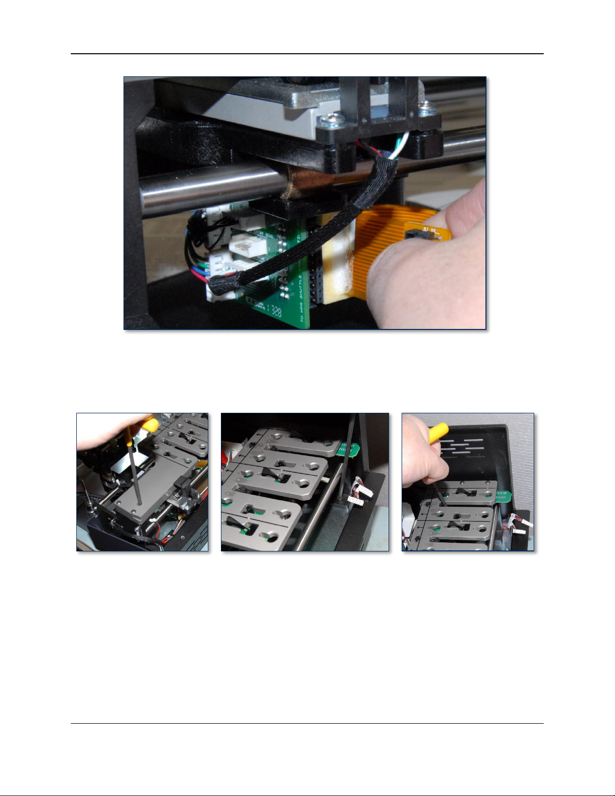
4 - Removal and Re-installation
Figure 4-35 - Disconnecting the Hopper Transport Flex Cable
12) Use the 5/32 in. ball end Allen wrench to remove the four screws that secure the four corners of the
hopper module to the top deck plate. Some screws require inserting the Allen wrench through
openings in the hopper deck plate. See Figure 4-30 and Figure 4-36 for reference.
Figure 4-36 –3 of 4 Hopper Module Screws (TOP RIGHT VIEW)
13) Locate the hopper transport belt. It will remain attached to the hopper transport during removal.
14) Release the tension on the hopper transport belt by using the 5/32” Allen wrench to loosen the belt
tension screw on the front of the hopper module (see Figure 4-37).
ExpressCard 2000| Instant Issuance Card Personalization System | Hardware Service Manual
Page 66
Page 67
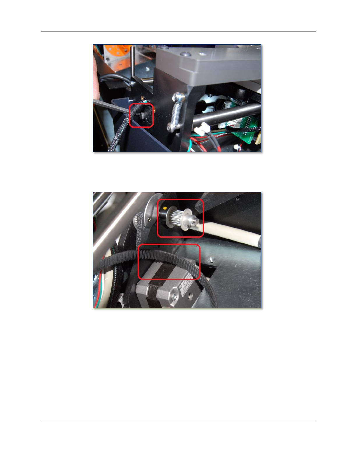
4 - Removal and Re-installation
Figure 4-37 - Hopper Transport Belt Tension Adjustment Screw (FRONT RIGHT VIEW)
15) Carefully slip the hopper transport belt off the gear of the motor mounted to the top deck plate, near
the rear of the hopper module (see Figure 4-38).
Figure 4-38 - Hopper Transport Belt and Drive Motor (FRONT RIGHT VIEW)
16) Use both hands to carefully lift the hopper module out of the device, making sure no cables are
snagged on the hopper module or the device, and set it aside.
ExpressCard 2000| Instant Issuance Card Personalization System | Hardware Service Manual
Page 67
Page 68

4 - Removal and Re-installation
To re-install the hopper module, follow these steps:
1) Note that if any cables or cable ties are too difficult to reach during the following steps, you can
remove the hopper deck (the steel plate on the top of the hopper module); use the 5/64” Allen wrench
to remove the five screws that secure it to the hopper module, and set the screws and deck aside.
2) On the replacement hopper module, move the hopper transport to hopper 4 (see section 2.8 How to
Safely Move Transports By Hand).
3) Using both hands, carefully insert the rear side of the hopper module into the device at a slight angle,
and rest it on the top deck plate so its screw holes line up with the corresponding holes in the top
deck. Make sure it doesn’t pinch any cables or the drive belt. See Figure 4-39.
Figure 4-39 - Re-installing Rear Side of Hopper Module First (TOP FRONT VIEW)
4) Carefully lower the front side of the hopper module into the device so its holes line up with the
corresponding holes in the top deck plate. Make sure it doesn’t pinch any cables or the drive belt.
See Figure 4-40.
Figure 4-40 - Re-installing Rear Side of Hopper Module First (TOP FRONT VIEW)
5) Pull any loose cables toward the outside of the device to make them easy to find, and to clear them
out of the way.
ExpressCard 2000| Instant Issuance Card Personalization System | Hardware Service Manual
Page 68
Page 69

4 - Removal and Re-installation
6) Move the hopper transport to the front of the device, just past hopper 7 and before it rotates to the
manual feed slot (see Figure 4-31 and section 2.8 How to Safely Move Transports By Hand).
7) Stick ¼” of double-stick tape to the hopper transport flex cable just behind the plug.
8) Plug the flex cable into the hopper transport so it points toward the rear of the device, and stick the
double-stick tape to the hopper transport’s motor as shown.
9) Make sure the hopper transport belt is looped around the drive gear at the front of the hopper
transport module as shown.
10) Route the EXC HOME SENS cable from the front of the hopper module to the right of the device,
around the hopper mounting legs, then toward the rear of the device as shown in Figure 4-41.
ExpressCard 2000| Instant Issuance Card Personalization System | Hardware Service Manual
Page 69
Page 70

4 - Removal and Re-installation
11) Loop a cable tie through the anchor point on the top deck plate near the front of the device, tie the
EXC HOME SENS cable to the other cables, and tighten and trim the cable tie (see Figure 4-41).
Figure 4-41 - EXC HOME SENS Cable Routing (TOP LEFT VIEW)
12) Continue routing the EXC HOME SENS cable along the right side of the device and thread it under
the right side of the HOPPER SHUTTLE board, then out the front as shown in Figure 4-42.
Figure 4-42 - Routing the EXC HOME SENSOR Cable (FRONT VIEW)
13) Use a miniature cable tie to fasten the EXC HOME SENS cable near the front of the device, securing
it to the bundle of cables that runs along the right side of the device (see Figure 4-43).
ExpressCard 2000| Instant Issuance Card Personalization System | Hardware Service Manual
Page 70
Page 71

4 - Removal and Re-installation
Figure 4-43 - Securing the EXC HOME SENS Cable (TOP VIEW FROM FRONT)
14) Use a miniature cable tie to fasten the EXC HOME SENS cable to the same bundle of cables, near the
flex cable as shown.
15) Locate the HOME SENS cable that comes from the rear of the hopper module. Route it along the
rear wall of the device to the left side of the hopper module, and below the shielding around the
image printer as shown in Figure 4-44. If there is not enough slack in the cable, use the 5/32” Allen
wrench to seat the cable below the axle of the hopper motor’s gear as shown in Figure 4-45.
ExpressCard 2000| Instant Issuance Card Personalization System | Hardware Service Manual
Page 71
Page 72
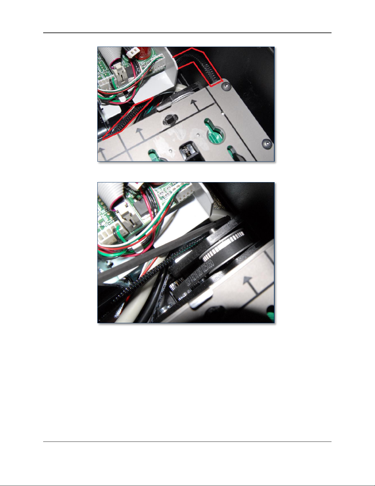
4 - Removal and Re-installation
Figure 4-44 - Preferred Routing for HOME SENS Cable (TOP VIEW FROM FRONT RIGHT)
Figure 4-45 – Optional Routing for Tighter HOME SENS Cable (TOP VIEW FROM FRONT RIGHT)
16) Continue routing the HOME SENS cable along the bundle of cables that runs below the left edge of
the hopper module. Use cable ties to re-bundle the cables as shown in Figure 4-46.
ExpressCard 2000| Instant Issuance Card Personalization System | Hardware Service Manual
Page 72
Page 73
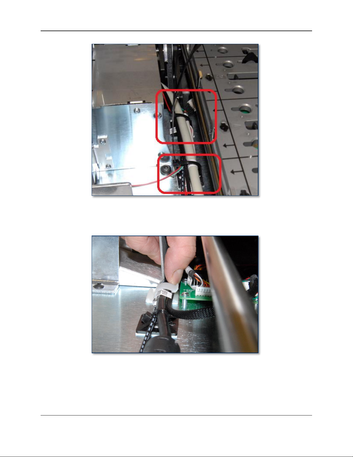
4 - Removal and Re-installation
Figure 4-46 - Routing the HOME SENS Cable (TOP FRONT VIEW)
17) Continue routing the HOME SENS cable under the clip just to the left of the HOPPER SHUTTLE
circuit board as shown in Figure 4-47.
Figure 4-47 - Routing the HOME SENS Cable (FRONT VIEW)
18) Plug the two sensor cables into the HOPPER SHUTTLE circuit board (see Figure 4-48).
a) The HOME SENS cable from the rear of the hopper module plugs into the left connector, labeled
HOME SENS.
b) The EXC HOME SENS cable from the front of the hopper module plugs into the right connector,
labeled EXC HOME SENS.
ExpressCard 2000| Instant Issuance Card Personalization System | Hardware Service Manual
Page 73
Page 74
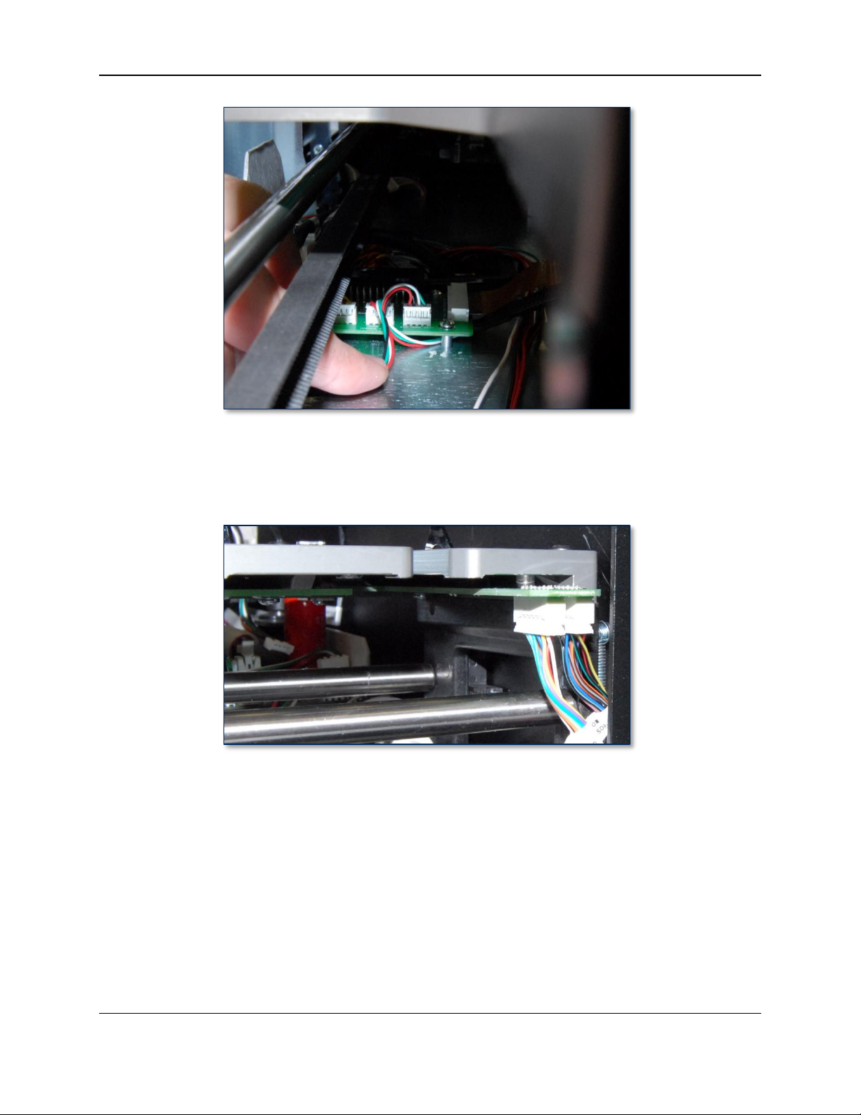
4 - Removal and Re-installation
Figure 4-48 - Sensor Cables Plugged In To HOPPER SHUTTLE Circuit Board (FRONT VIEW)
19) Plug the two sensor cables at the rear of the device into the two plugs on the circuit board at the top
rear right of the hopper module. The cable labeled “…to J2…” goes to the REAR plug, and the cable
labeled “…to J1…” goes to the FRONT plug. See Figure 4-49.
Figure 4-49 - Sensor Cables at Rear of Hopper Module (RIGHT VIEW)
20) Loop the hopper transport drive belt around the gear of the hopper drive motor at the rear of the
device as shown in Figure 4-50.
ExpressCard 2000| Instant Issuance Card Personalization System | Hardware Service Manual
Page 74
Page 75

4 - Removal and Re-installation
Figure 4-50 - Attaching Hopper Transport Drive Belt (FRONT RIGHT VIEW)
21) Use the 5/32” Allen wrench to insert and tighten the four screws that secure the hopper module to the
top deck plate (see Figure 4-30 at the beginning of this section).
22) Use the 5/32” Allen wrench to tighten the belt tensioner screw on the front of the hopper module (see
Figure 4-37) so the top and bottom of the drive belt are parallel with each other and the belt feels
tight to your fingers. During testing, the belt should not slip or make grinding sounds. If it does, the
tension may need to be re-adjusted.
23) Test the new hopper module manually by moving the hopper transport along the full range from front
to back (see section 2.8 How to Safely Move Transports By Hand). Make sure it does not touch
any cables or other parts along its entire path, that the drive motor at the rear of the device moves
along with it, and that it does not make any unusual sounds, such as clicking, rubbing, or grinding.
24) Perform any additional service that requires the device to be powered off and open.
25) Re-install the cover and top access door by following the steps in sections 4.4 and 4.2 respectively.
26) Move the hopper transport to the front of the device, just past hopper 7 and before it rotates to the
manual feed slot (see Figure 4-31 and section 2.8 How to Safely Move Transports By Hand).
27) Re-install the card stock hoppers.
28) Close the top access door.
29) Re-attach the power cable, network cable, and any security hardware.
30) Power up the device.
31) Perform any relevant adjustments from section 5 Adjustments, notably section 5.2 How to
Calibrate the Hopper Transport Module.
32) From the touchscreen, navigate to Menu > Samples, create a sample card, and make sure the device
functions properly and the sample looks correct.
ExpressCard 2000| Instant Issuance Card Personalization System | Hardware Service Manual
Page 75
Page 76

4 - Removal and Re-installation
4.6 How to Remove / Re-install the Image Print Head
For detailed instructions to replace the image print head, see 99875600 EC2000 User Installation and
Operation Manual.
ExpressCard 2000| Instant Issuance Card Personalization System | Hardware Service Manual
Page 76
Page 77

4 - Removal and Re-installation
Approximate time to remove: 15 minutes plus any sub-procedures
Approximate time to re-install: 15 minutes plus any sub-procedures
4.7 How to Remove / Re-install the Image Printer Module
The image printer, located in the rear center of the device, takes blank card stock from the hopper
transport, encodes any required data onto the card, produces images on both sides, and ejects the card out
the other side to be retrieved by the XY transport.
Figure 4-51 - Removing / Re-installing the Image Printer (FRONT RIGHT VIEW)
Follow these steps to remove the image printer module:
1) If you are replacing any modules that do NOT require silicone adhesive, replace those first. That will
reduce the risk of breaking the image printer power connector’s adhesive during other service.
2) Prepare the device for replacing parts by following the steps in section 4.1 How to Prepare the
Device for Removing / Re-installing Modules. At the end, the device should be powered down with
all external cables safely disconnected.
ExpressCard 2000| Instant Issuance Card Personalization System | Hardware Service Manual
Page 77
Page 78

4 - Removal and Re-installation
3) Disengage and lean back the top access door by following the steps in section 4.2 How to Remove /
Re-install the Top Access Door up to the point where the top access door is leaning up and back
behind the device (Figure 4-3).
4) Remove the image printer ribbon and set it aside in a secure location or give it to the customer for
temporary storage or secure disposal.
5) Move the hopper transport away from the image printer, toward the front of the device (see section
2.8 How to Safely Move Transports By Hand).
6) On the rear right side of the image printer, locate the power cable shown in Figure 4-52. Remove
any adhesive securing it to its connector, and disconnect it.
Figure 4-52 - Image Printer Power Connector (FRONT RIGHT VIEW)
7) From the power connector, look left across the rear wall of the EC2000, past a motor, to a circuit
board with several white connectors. Find connector J31 on the circuit board, and unplug the black
insulated cable from it (see Figure 4-53 and Figure 4-56). This is the image printer USB cable.
Figure 4-53 - Image Printer USB Cable Connected to J31 (TOP VIEW FROM REAR)
ExpressCard 2000| Instant Issuance Card Personalization System | Hardware Service Manual
Page 78
Page 79

4 - Removal and Re-installation
8) Near the front left screw of the image printer, locate the cable labeled Y END SENSOR, shown in
Figure 4-54, and disconnect it.
Figure 4-54 - Image Printer Exit Sensor Connector (TOP LEFT VIEW)
9) Use the 5/32” Allen wrench to unscrew the four screws and washers that attach the four corners of the
image printer to the top deck plate (see Figure 4-51).
10) Use both hands to carefully lift the printer out of the device, making sure no cables catch on it as you
remove it. Set it aside.
ExpressCard 2000| Instant Issuance Card Personalization System | Hardware Service Manual
Page 79
Page 80

4 - Removal and Re-installation
To re-install the image printer module, follow these steps:
1) Clear all cables out of the way to make room on the top deck plate for the replacement image printer.
2) Carefully lower the replacement image printer, tilted slightly downward toward the hoppers, and line
up the screw holes in its base with the screw holes in the top deck plate.
3) Make sure the downward-facing sheet metal tabs in the base of the image printer insert into the
corresponding slots on the top deck plate (see Figure 4-55). You may have to push a bit on the sheet
metal of the image printer’s base to line up the tabs.
Figure 4-55 - Seat Image Printer Tabs In Slots (TOP RIGHT VIEW)
4) Use the 5/32” Allen wrench to re-fasten the screws and washers that secure the image printer to the
top deck plate (see Figure 4-51).
5) Re-connect the power cable, reconnect the card exit sensor, and reconnect the USB cable to J31.
ExpressCard 2000| Instant Issuance Card Personalization System | Hardware Service Manual
Page 80
Page 81
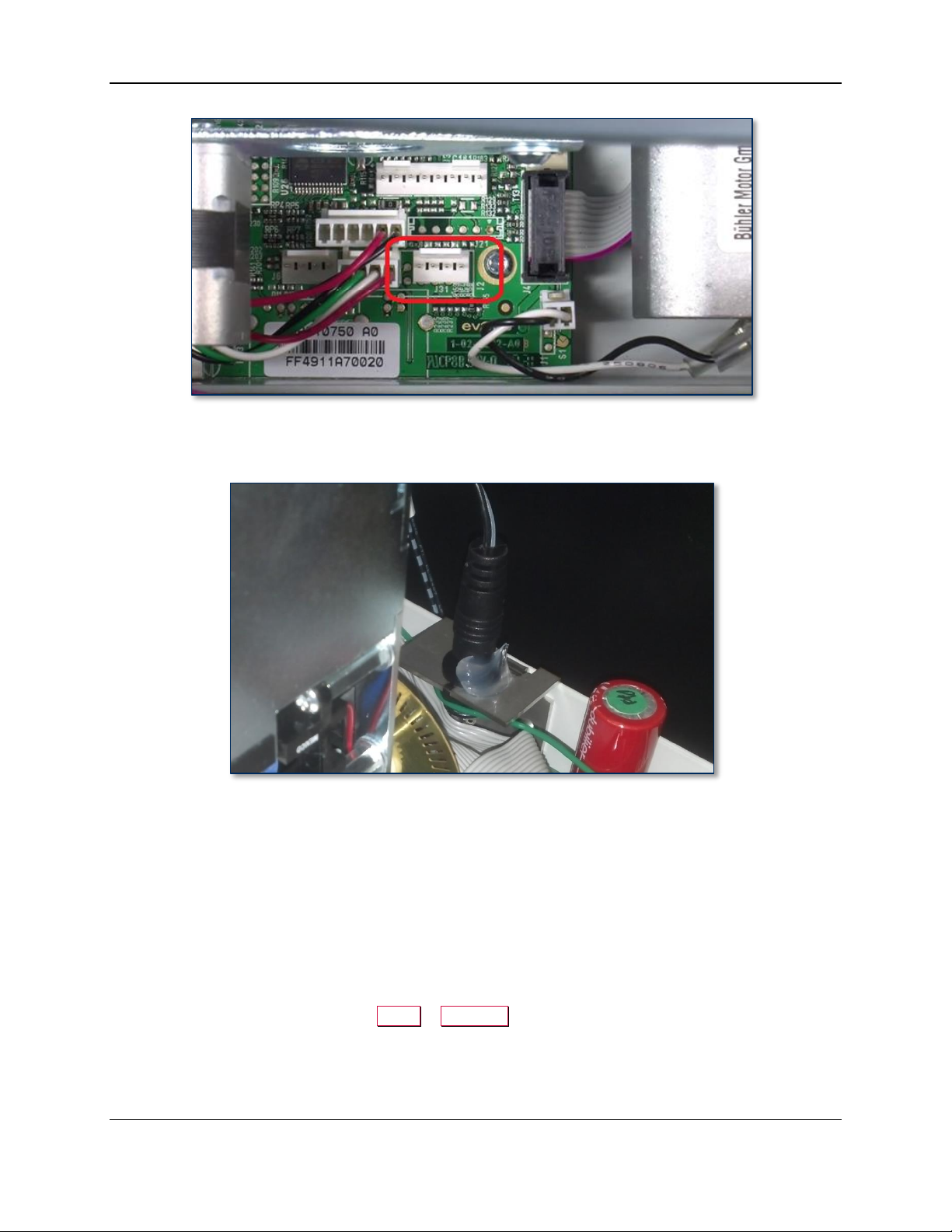
4 - Removal and Re-installation
Figure 4-56 - Re-connect USB Cable to J31 (TOP VIEW FROM REAR)
6) Secure the power cable to its connector using a bead of silicone adhesive as shown in Figure 4-57.
Figure 4-57 - Silicone Adhesive On Image Printer Power Connector (FRONT RIGHT VIEW)
7) Re-attach the top access door by reversing the steps you used to lean it back.
8) Install the original printer ribbon, or obtain and install a new image printer ribbon from the customer.
9) Re-connect the power and network cables to the device and power it up.
10) Configure the image printer ribbon following the steps provided in 99875600 ExpressCard 2000
User Installation and Operation Manual.
11) Perform any relevant adjustments from section 5 Adjustments, notably section 5.6 How to
Calibrate the Image Printer.
12) Close and secure the top access door.
13) From the touchscreen, navigate to Menu > Samples, create a sample card, and make sure the device
functions properly and the sample looks correct.
ExpressCard 2000| Instant Issuance Card Personalization System | Hardware Service Manual
Page 81
Page 82

4 - Removal and Re-installation
4.8 How to Remove / Re-install the XY Transport Ribbon Cable
This section provides information for replacing just the XY transport ribbon cable, which occasionally
must be replaced without replacing the entire module. For instructions on removing and re-installing the
entire XY transport module, see section 4.9 How to Remove / Re-install the XY Transport.
Figure 4-58 - XY Transport Showing Ribbon Cable (FRONT VIEW)
To remove the XY transport module’s ribbon cable, follow these steps:
1) Prepare the device for replacing parts by following the steps in section 4.1 How to Prepare the
Device for Removing / Re-installing Modules. At the end, the device should be powered down with
all external cables safely disconnected.
2) Open the top access door by following the steps in section 2.7 How to Open the Top Access Door.
3) Move the XY transport to the front of the device to expose its cable and its connection to the circuit
board (“breakout board”) on the base plate of the device (see Figure 4-59 and section 2.8 How to
Safely Move Transports By Hand).
ExpressCard 2000| Instant Issuance Card Personalization System | Hardware Service Manual
Page 82
Page 83

4 - Removal and Re-installation
Figure 4-59 - XY Transport at Front of Device Exposing Breakout Board (TOP VIEW)
4) On the rear side of the XY transport, locate the two retaining clips that secure the ribbon cable to the
transport. Lift both clips firmly toward the ceiling to unlock and eject the cable from the circuit
board, then disconnect the ribbon cable. See Figure 4-60.
Figure 4-60 - Unlocking XY Transport Ribbon Cable (TOP VIEW FROM LEFT / REAR LEFT VIEW)
5) Open the clip that secures the ribbon cable to the top deck plate.
ExpressCard 2000| Instant Issuance Card Personalization System | Hardware Service Manual
Page 83
Page 84

4 - Removal and Re-installation
6) Disconnect the ribbon cable from the breakout board on the top deck plate, and set the cable aside.
7) If there is adhesive on any of the connectors, peel or gently scrape it off and discard it.
ExpressCard 2000| Instant Issuance Card Personalization System | Hardware Service Manual
Page 84
Page 85

4 - Removal and Re-installation
To re-install the XY transport ribbon cable, follow these steps:
1) Locate the end of the cable labeled TO J6 XY TRANSPORT BOARD and connect it to the
breakout board on the top deck plate, with the cable coming off the board toward the front of the
device. Press down to make sure the connection is solid.
Figure 4-61 - Breakout Board Connection of XY Transport Ribbon Cable (TOP VIEW FROM LEFT)
2) Route the cable through the clip that secures it to the top deck plate, close the clip, and press down
until you feel it click in place (see Figure 4-62).
Figure 4-62 - Locking XY Transport Ribbon Cable In Place (TOP VIEW FROM LEFT)
3) Make sure the loose end of the cable says TO J2 X CLAMP BOARD and is oriented as shown in
Figure 4-63.
ExpressCard 2000| Instant Issuance Card Personalization System | Hardware Service Manual
Page 85
Page 86

4 - Removal and Re-installation
Figure 4-63 - XY Transport End of Ribbon Cable (TOP VIEW FROM LEFT)
4) Connect the cable to the XY transport as shown in Figure 4-64. It should come off the XY transport
toward the front of the device before looping back toward the breakout board.
Figure 4-64 - XY Transport Ribbon Cable Installed (TOP VIEW FROM LEFT)
5) Push the retaining clips down toward the printed circuit board and pinch to lock them in place.
ExpressCard 2000| Instant Issuance Card Personalization System | Hardware Service Manual
Page 86
Page 87

4 - Removal and Re-installation
6) Move the XY transport to the rear of the device (see section 2.8 How to Safely Move Transports By
Hand) and inspect it to make sure it looks like Figure 4-58.
7) Use the belt to push the XY Transport back and forth across the full length of the rails to make sure
the ribbon cable moves as it should:
a) The ribbon cable should wind and unwind in a straight line; it should not twist, bend diagonally,
or move to the side.
b) The ribbon cable should not contact any objects in its path.
c) If the ribbon cable touches other parts or bends incorrectly, re-check its connections and
orientation according to the installation steps, then re-test.
8) Complete any other service that requires the device to be powered off and open.
9) Close the top access door.
10) Re-attach the power cable, network cable, and any security hardware.
11) Power up the device.
12) From the touchscreen, navigate to Menu > Samples, create a sample card, and make sure the device
functions properly and the sample looks correct.
ExpressCard 2000| Instant Issuance Card Personalization System | Hardware Service Manual
Page 87
Page 88

4 - Removal and Re-installation
Approximate time to remove: 15 minutes plus any sub-procedures
Approximate time to re-install: 15 minutes plus any sub-procedures
4.9 How to Remove / Re-install the XY Transport Module
The XY transport receives cards from the image printer module and moves them to the embosser module,
then to the exit transport module. It is located along the left side of the device.
Figure 4-65 - Removing and Re-Installing the XY Transport Module (FRONT RIGHT VIEW)
Follow these steps to remove the XY transport module from the device:
1) Prepare the device for replacing parts by following the steps in section 4.1 How to Prepare the
Device for Removing / Re-installing Modules. At the end, the device should be powered down with
all external cables safely disconnected.
2) Disengage and lean back the top access door by following the steps in section 4.2 How to Remove /
Re-install the Top Access Door up to the point where the top access door is leaning up and back
behind the device.
3) Move the XY transport toward the front of the device (see section 2.8 How to Safely Move
Transports By Hand).
4) Locate the XY transport’s ground cable, which is connected to the deck plate behind the image printer
as shown in Figure 4-66.
ExpressCard 2000| Instant Issuance Card Personalization System | Hardware Service Manual
Page 88
Page 89

4 - Removal and Re-installation
Figure 4-66 - XY Transport Ground Cable (TOP VIEW FROM REAR)
5) Use the No. 2 Philips screwdriver to remove the screw, and set it aside.
6) Snap open the XY transport ribbon cable clamp between the rails as shown in Figure 4-67.
Figure 4-67 - XY Transport Ribbon Cable (TOP VIEW FROM FRONT)
7) Grasping the XY transport ribbon cable by the connector, not the cable itself, disconnect it from the
top deck.
8) Locate the connectors in the middle of the Y stepper connection cable, which runs along the left rail
of the XY transport (see Figure 4-68).
9) Hold the two connectors (not the wires), and disconnect them.
ExpressCard 2000| Instant Issuance Card Personalization System | Hardware Service Manual
Page 89
Page 90

4 - Removal and Re-installation
Figure 4-68 - XY Transport Y Stepper Connection Cable (TOP VIEW FROM LEFT)
10) Use the 1/8” Allen wrench to remove the three screws securing the XY transport to the top deck plate
near the rear of the device (see Figure 4-65) and set them aside.
11) Move the XY transport toward the rear of the device (see section 2.8 How to Safely Move
Transports By Hand).
12) Use the 1/8” Allen wrench to remove the three screws securing the XY transport to the top deck plate
near the front of the device (see Figure 4-65) and set them aside.
13) Use both hands on the rails to carefully lift the XY transport module out of the device, making sure
no cables catch on any other modules, and set it aside.
ExpressCard 2000| Instant Issuance Card Personalization System | Hardware Service Manual
Page 90
Page 91

4 - Removal and Re-installation
To re-install the XY transport module, follow these steps:
1) Place the XY transport onto the top deck with the ground cable pointing toward the rear of the device,
lining up the holes in the XY transport module with the corresponding holes in the top deck plate.
2) Inspect around and underneath the XY transport to make sure it isn’t pressing any cables against the
top deck plate or other modules.
3) Make sure the four keys at the corners of the XY transport are seated in the corresponding slots in the
top deck plate (see Figure 4-69). Push the base of the XY transport forward and backward, left and
right, to make sure they prevent it from moving around.
Figure 4-69 - XY Transport Base Keys and Top Deck Plate Holes (TOP RIGHT VIEW)
4) Move the XY transport carriage toward the rear of the device (see section 2.8 How to Safely Move
Transports By Hand).
5) Use the 1/8” Allen wrench to fasten and tighten the three screws securing the XY transport to the top
deck plate near the front of the device (see Figure 4-65).
6) Move the XY transport carriage toward the front of the device (see section 2.8 How to Safely Move
Transports By Hand).
7) Use the 1/8” Allen wrench to fasten and tighten the three screws securing the XY transport to the top
deck plate near the rear of the device (see Figure 4-65).
8) Re-connect the Y stepper connection cable (see Figure 4-68).
9) Re-connect the XY transport ribbon cable, with the cable coming off toward the front of the device as
shown in Figure 4-67.
10) Hold the ribbon cable in place in the middle of the clamp. Being careful not to pinch the cable, close
the clamp and press until you feel it lock closed.
11) Use the No. 2 Philips screwdriver (and optionally the hemostat pliers) to re-attach the XY transport
ground cable to the top deck plate behind the image printer.
12) Re-attach the top access door by reversing the steps you used to lean it back.
13) Calibrate the XY transport using the information in section 5.3 How to Calibrate the XY
Transport.
14) From the touchscreen, navigate to Menu > Samples, create a sample card, and make sure the device
functions properly and the sample looks correct.
ExpressCard 2000| Instant Issuance Card Personalization System | Hardware Service Manual
Page 91
Page 92

4 - Removal and Re-installation
15) If the EC2000 does not power up or function properly, contact MagTek Support Services for
assistance (see Appendix A Technical Support).
ExpressCard 2000| Instant Issuance Card Personalization System | Hardware Service Manual
Page 92
Page 93

4 - Removal and Re-installation
4.10 How to Remove / Re-install Embosser Fonts
Under normal circumstances, the characters on the embosser module’s daisy wheel do not need to be
removed. Embosser characters should be removed and replaced as little as possible, because removal
causes the tine to wear and eventually become less effective at holding characters. If a tine breaks,
however, it may be necessary to move its character to a new tine.
Figure 4-70 - Removing a Character from the Embosser Module Daisy Wheel
To remove a character from a tine on the embosser module’s daisy wheel, follow these steps:
1) Prepare the device for replacing parts by following the steps in section 4.1 How to Prepare the
Device for Removing / Re-installing Modules. At the end, the device should be powered down with
all external cables safely disconnected.
2) Insert an X-Acto knife between the tine and the character as shown in Figure 4-70.
3) Carefully pry the character toward the ceiling until you can remove it with your fingers.
4) Prepare the character for installation in the new time by making sure it is oriented correctly.
5) Support the tine, then press the character into place with your fingers.
6) Notify the EC2000’s software that the character has moved. For detailed instructions, refer to section
2.9.4 How to Use the Character Mapping Page.
ExpressCard 2000| Instant Issuance Card Personalization System | Hardware Service Manual
Page 93
Page 94
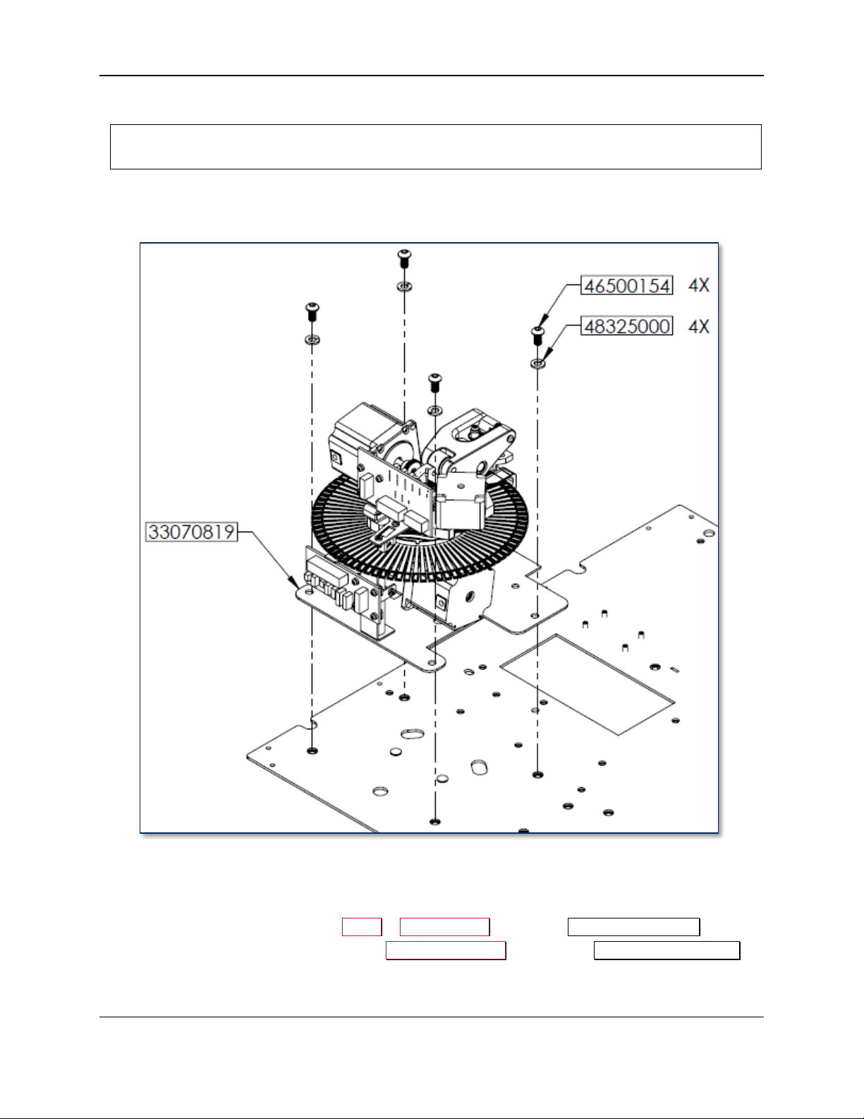
4 - Removal and Re-installation
Approximate time to remove: 15 minutes plus any sub-procedures
Approximate time to re-install: 30 minutes plus any sub-procedures
4.11 How to Remove / Re-install the Embosser Module
The embosser module, located at the front left corner of the device, punches raised and indented
characters into cards as they are held by the XY transport.
Figure 4-71 - Embosser Module (FRONT RIGHT VIEW)
To remove the embosser module, follow these steps:
1) Power on the device and open the top access door.
2) From the touchscreen, navigate to Menu > Maintenance to open the Maintenance Menu page.
3) If the device has a top indenter, press the Unload Cartridge button under Top Indent Cartridge to
move the front indent cartridge into the unload position. Remove the top indent cartridge and set it
aside in a secure location or give it to the customer for temporary storage or secure disposal.
ExpressCard 2000| Instant Issuance Card Personalization System | Hardware Service Manual
Page 94
Page 95
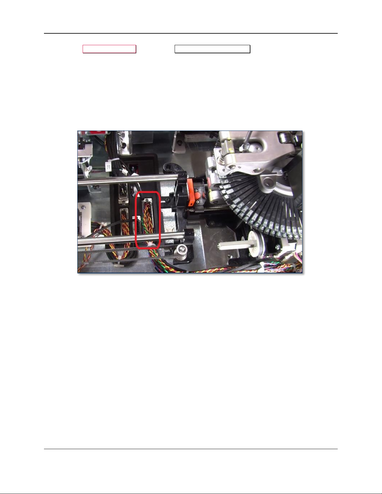
4 - Removal and Re-installation
4) Press the Unload Cartridge button in the Bottom Indent Cartridge section to move the rear indent
cartridge into the unload position. Remove the rear indent cartridge and set it aside in a secure
location, or give it to the customer for temporary storage or secure disposal.
5) Prepare the device for replacing parts by following the steps in section 4.1 How to Prepare the
Device for Removing / Re-installing Modules. At the end, the device should be powered down with
all external cables safely disconnected.
6) Remove the cover by following the steps in section 4.4 How to Remove / Re-install the Cover.
7) Carefully disconnect the embosser’s cable from the top deck, making sure not to break any wires.
Figure 4-72 shows the cable as seen from the left side of the device.
Figure 4-72 - Embosser Cable (TOP VIEW FROM LEFT)
8) Re-route the embosser cable so the connector rests on top of the XY transport rails, as shown in
Figure 4-73.
ExpressCard 2000| Instant Issuance Card Personalization System | Hardware Service Manual
Page 95
Page 96
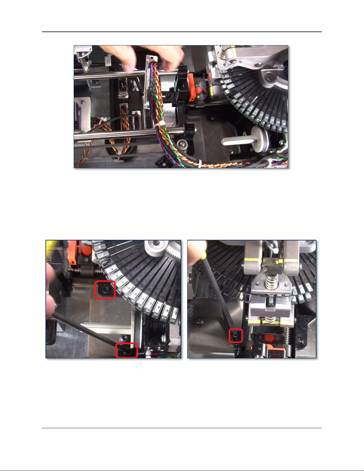
4 - Removal and Re-installation
Figure 4-73 - Safe Removal Position for Embosser Cable (TOP VIEW FROM LEFT)
9) In each of the following steps, rotate the embosser daisy wheel so only empty tines are near the Allen
wrench. This saves time if the wrench slips and breaks a tine; if the broken tine were not empty, you
would have to re-install the font to another tine and re-map it in the software.
10) Use the 5/32” ball-end Allen wrench to remove the three screws that attach the rear indent module to
the embosser. The left image in Figure 4-74 shows two screws as seen from the left side of the
device, and the right image shows the final screw as seen from the rear of the device.
Figure 4-74 - Unfastening Rear Indent Module (TOP VIEW FROM LEFT and TOP VIEW FROM REAR)
11) Use the 5/32” ball-end Allen wrench to remove the four screws and washers that attach the embosser
to the top deck plate, and set them aside. The left image in Figure 4-75 shows two screws as seen
from the front of the device, and the right image shows the other two as seen from the rear of the
device.
ExpressCard 2000| Instant Issuance Card Personalization System | Hardware Service Manual
Page 96
Page 97
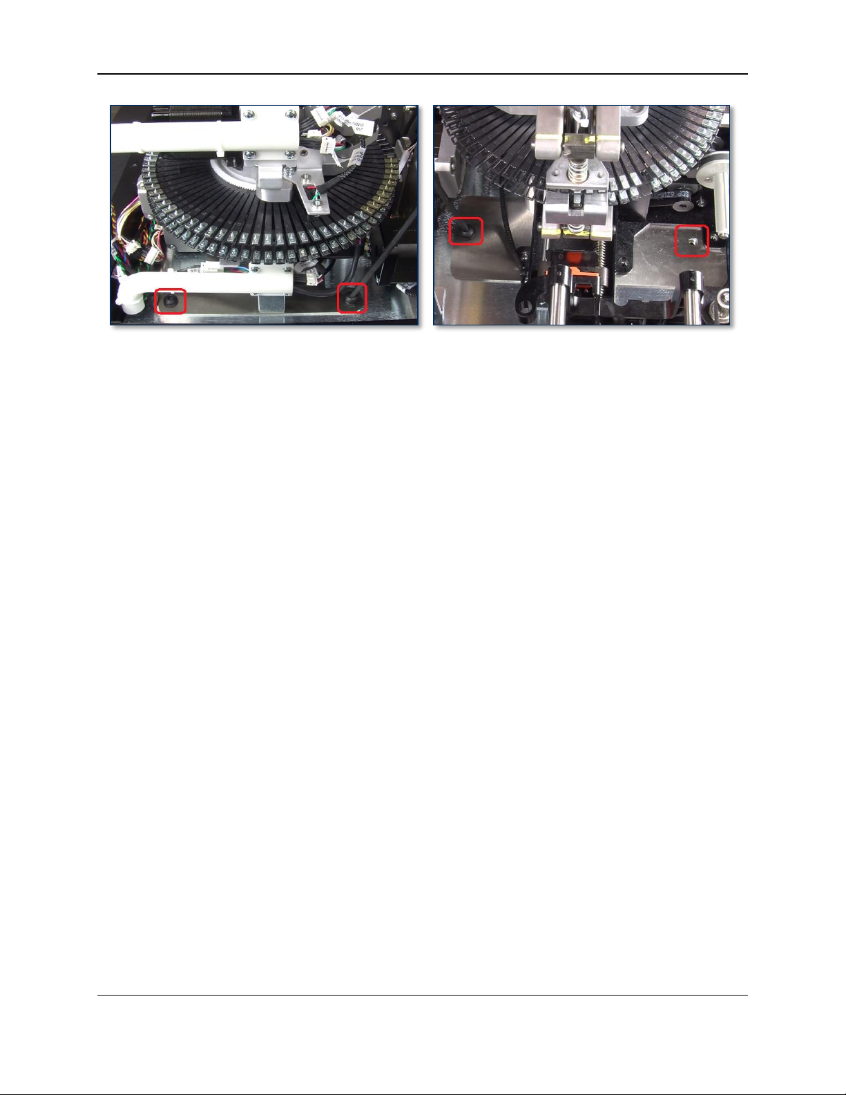
4 - Removal and Re-installation
Figure 4-75 - Unfastening Embosser (TOP VIEW FROM FRONT and TOP VIEW FROM REAR)
12) Use both hands to lift the embosser and indenter modules out of the device, making sure the embosser
cable does not catch on anything on the way out. Set the modules aside.
ExpressCard 2000| Instant Issuance Card Personalization System | Hardware Service Manual
Page 97
Page 98

4 - Removal and Re-installation
To re-install the embosser module, follow these steps:
1) Use both hands to lower the replacement embosser and indenter modules (already together), into the
device in the same position and orientation as the one you just removed. Line up the four corner
screw holes in the embosser with the four corresponding screw holes in the top deck plate.
2) Make sure the two raised keys stamped into the top deck plate (see Figure 4-76) are seated in the
indentations in the base of the embosser. Push the embosser forward, backward, left, and right to
make sure they are holding the embosser in place.
Figure 4-76 - Embosser Base Keys In Top Deck Plate (TOP RIGHT VIEW)
3) Use the 5/32” ball-end Allen wrench to re-fasten and tighten the four screws and washers that attach
the corners of the embosser to the top deck plate.
ExpressCard 2000| Instant Issuance Card Personalization System | Hardware Service Manual
Page 98
Page 99
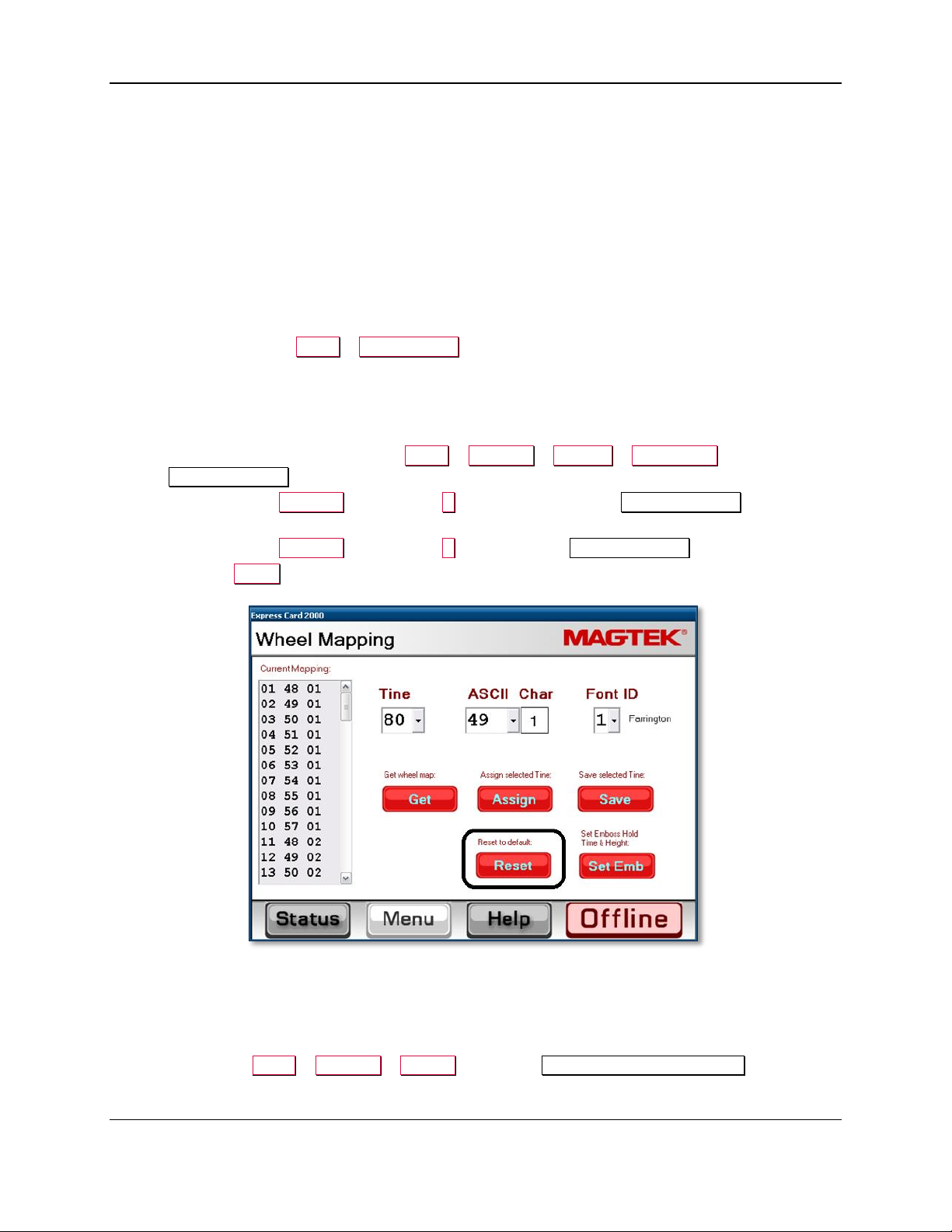
4 - Removal and Re-installation
4) Line up the three screw holes in the indenter module with the three screw holes in the embosser
module and the top deck plate. Use the 5/32” ball-end Allen wrench to re-fasten the three screws that
attach the indenter module to the embosser module.
5) Route the embosser cable along the left wall of the device, then under the XY transport belt and rails
as shown in Figure 4-72.
6) Plug the embosser cable back in to its connector on the top deck plate. Press firmly on the two metal
sides of the connector to make sure it is seated tightly.
7) Perform any additional service that requires the device to be powered off and open.
8) Re-install the cover and top access door by following the steps in sections 4.4 and 4.2 respectively.
9) Re-attach the power cable and network cable, and power on the device.
10) Use the tools found in Menu > Maintenance to re-install any indent cartridges you removed at the
beginning of these steps. Install the original cartridges or obtain new ones from the customer.
11) If you have installed a new embosser with all characters in factory-default locations, and if the
customer has no custom characters installed, wait until other service is complete and the device is
ready to power up, then reset the character mappings in the touchscreen software as follows:
a) From the touchscreen, navigate to Menu > Settings > Service > Wheel Map to open the first
Wheel Mapping password page.
b) Enter password 4567890 and press the E key to open the second Wheel Mapping password
page.
c) Enter password 0987654 and press the E key to open the Wheel Mapping page.
d) Press the Reset button.
12) If the original embosser had custom characters installed, carry them over to the same locations on the
new embosser’s daisy wheel by following the steps in section 4.10 How to Remove / Re-install
Embosser Fonts and section 2.9.4 How to Use the Character Mapping Page.
13) Calibrate the embosser using the information in section 5.4 How to Calibrate the Embosser.
14) Power up the device and test it, paying special attention to the following:
a) Navigate to Menu > Settings > Tuning to open the Tuning (Move Embossing) page.
ExpressCard 2000| Instant Issuance Card Personalization System | Hardware Service Manual
Page 99
Page 100

4 - Removal and Re-installation
b) Make sure the ribbon information in the upper left corner matches the ribbon you are using. If it
doesn’t, set and calibrate the ribbon (see the ExpressCard 2000 User Installation and
Operation Manual for details).
c) Press the Print button. The EC2000 will create a test card with all characters and all font IDs.
d) Inspect the card to make sure the embosser is working as expected.
15) If the EC2000 does not power up or function properly, contact MagTek Support Services for
assistance (see Appendix A Technical Support).
ExpressCard 2000| Instant Issuance Card Personalization System | Hardware Service Manual
Page 100
 Loading...