

Page 1

Bluetooth MagneSafe V5
Swipe Reader
TECHNICAL REFERENCE MANUAL
PART NUMBER 99875398-3
APRIL 2011
REGISTERED TO ISO 9001:2008
1710 Apollo Court
Seal Beach, CA 90740
Phone: (562) 546-6400
FAX: (562) 546-6301
Technical Support: (651) 415-6800
www.magtek.com
Page 2

Copyright© 2001-2011
Rev Number
Date
Notes
1.01
24 Apr 2009
Initial Release
2.01
10 Feb 2010
Added Encrypted Bulk Data command; added reference to
doc #99875388 to USB section; updated Specifications table
3.01
19 April 2011
Updated MP flags property
MagTek®, Inc.
Printed in the United States of Americ a
Information in this document is subject to change without notice. No part of this document may be
reproduced or transmitted in any form or by any means, electronic or mechanical, for any purpose,
without the express written permission of MagTek, Inc.
MagTek® is a registered trademark of MagTek, Inc.
MagnePrint® is a registered trademark of MagTek, Inc.
MagneSafe™ is a trademark of MagTek, Inc.
Magensa™ is a trademark of MagTek, Inc.
REVISIONS
ii
Page 3

LIMITED WARRANTY
MagTek warrants that the products sold pursuant to this Agreement will perform in accordance with MagTek’s
published specifications. This warranty shall be provided only for a period of one year from the date of the
shipment of the product from MagTek (the “Warranty Period”). This warranty shall apply only to the “Buyer”
(the original purchaser, unless that entity resells the product as authorized by MagTek, in which event this
warranty shall apply only to the first repurchaser).
During the Warranty Period, should this product fail to conform to MagTek’s specifications, MagTek will, at its
option, repair or replace this product at no additional charge except as set forth below. Repair parts and
replacement products will be furnished on an exchange basis and will be either reconditioned or new. All replaced
parts and products become the property of MagTek. This limited warranty does not include service to repair
damage to the product resulting from accident, disaster, unreasonable use, misuse, abuse, negligence, or
modification of the product not authorized by MagTek. MagTek reserves the right to examine the alleged
defective goods to determine whether the warranty is applicable.
Without limiting the generality of the foregoing, MagTek specifically disclaims any liability or warranty for
goods resold in other than MagTek’s original packages, and for goods modified, altered, or treated without
authorization by MagTek.
Service may be obtained by delivering the product during the warranty period to MagTek (1710 Apollo Court,
Seal Beach, CA 90740). If this product is delivered by mail or by an equivalent shipping carrier, the customer
agrees to insure the product or assume the risk of loss or damage in transit, to prepay shipping charges to the
warranty service location, and to use the original shipping container or equivalent. MagTek will return the
product, prepaid, via a three (3) day shipping service. A Return Material Authorization (“RMA”) number must
accompany all returns. Buyers may obtain an RMA number by contacting Technical Support at (888) 624-8350.
EACH BUYER UNDERSTANDS THAT THIS MAGTEK PRODUCT IS
OFFERED AS IS.
MAGTEK MAKES NO OTHER WARRANTY , EXPRESS OR
IMPLIED, AND MAGTEK DISCLAIMS ANY WARRANTY OF ANY OTHER
KIND, INCLUDING ANY WARRANTY OF MERCHANTABILITY OR FITNESS
FOR A PARTICULAR PURPOSE.
IF THIS PRODUCT DOES NOT CONFORM TO MAGTEK’S SPECIFICATIONS, THE SOLE REMEDY
SHALL BE REPAIR OR REPLACEMENT AS PROVIDED ABOVE. MAGTEK’S LIABILITY, IF ANY,
SHALL IN NO EVENT EXCEED THE TOTAL AMOUNT PAID TO MAGTEK UNDER THIS
AGREEMENT. IN NO EVENT WILL MAGTEK BE LIABLE TO THE BUYER FOR ANY DAMAGES,
INCLUDING ANY LOST PROFITS, LOST SAVINGS, OR OTHER INCIDENTAL OR CONSEQUENTIAL
DAMAGES ARISING OUT OF THE USE OF, OR INABILITY TO USE, SUCH PRODUCT, EVEN IF
MAGTEK HAS BEEN ADVISED OF THE POSSIBILITY OF SUCH DAMAGES, OR FOR ANY CLAIM BY
ANY OTHER PARTY.
LIMITATION ON LIABILITY
EXCEPT AS PROVIDED IN THE SECTIONS RELATING TO MAGTEK’S LIMITED WARRANTY,
MAGTEK’S LIABILITY UNDER THIS AGREEMENT IS LIMITED TO THE CONTRACT PRICE OF THIS
PRODUCT.
MAGTEK MAKES NO OTHER WARRANTIES WITH RESPECT TO THE PRODUCT, EXPRESSED OR
IMPLIED, EXCEPT AS MAY BE STATED IN THIS AGREEMENT, AND MAGTEK DISCLAIMS ANY
IMPLIED WARRANTY, INCLUDING WITHOUT LIMITATION ANY IMPLIED WARRANTY OF
MERCHANTABILITY OR FITNESS FOR A PARTICULAR PURPOSE.
MAGTEK SHALL NOT BE LIABLE FOR CONTINGENT, INCIDENTAL, OR CONSEQUENTIAL
DAMAGES TO PERSONS OR PROPERTY. MAGTEK FURTHER LIMITS ITS LIABILITY OF ANY KIND
WITH RESPECT TO THE PRODUCT, INCLUDING ANY NEGLIGENCE ON ITS PART, TO THE
CONTRACT PRICE FOR THE GOODS.
MAGTEK’S SOLE LIABILITY AND BUYER’S EXCLUSIVE REMEDIES ARE STATED IN THIS SECTION
AND IN THE SECTION RELATING TO MAGTEK’S LIMITED WARRANTY.
iii
Page 4

FCC WARNING STATEMENT
This equipment has been tested and was found to comply with the limits for a Class B digital device pursuant to
Part 15 of FCC Rules. These limits are designed to provide reasonable protection against harmful interference
when the equipment is operated in a residential environment. This equipment generates, uses, and can radiate
radio frequency energy and, if not installed and used in accordance with the instruction manual, may cause
harmful interference with radio communications. However, there is no guarantee that interference will not occur
in a particular installation.
FCC COMPLIANCE STATEMENT
This device complies with Part 15 of the FCC Rules. Operation of this device is subject to the following two
conditions: (1) this device may not cause harmful interference, and (2) this device must accept any interference
received, including interference that may cause undesired operation.
CANADIAN DOC STATEMENT
This digital apparatus does not exceed the Class B limits for radio noise from digital apparatus set out in the
Radio Interference Regulations of the Canadian Department of Communications.
Le présent appareil numérique n’émet pas de bruits radioélectriques dépassant les limites applicables aux
appareils numériques de la classe B prescrites dans le Réglement sur le brouillage radioélectrique édicté par le
ministère des Communications du Canada.
This Class B digital apparatus complies with Canadian ICES-003.
Cet appareil numériqué de la classe B est conformé à la norme NMB-003 du Canada.
CE STANDARDS
Testing for compliance with CE requirements was performed by an independent laboratory. The unit under test
was found compliant with s tandards established for Class B devices.
UL/CSA
This product is recognized per Underwriter Laboratories and Canadian Underwriter Laboratories 1950.
RoHS STATEMENT
When ordered as RoHS compliant, this product meets the Electrical and Electronic Equipment (EEE) Reduction
of Hazardous Substances (RoHS) European Directive 2002/95/EC. The marking is clearly recognizable, either as
written words like “Pb-free”, “lead-free”, or as another clear symbol ( ).
BLUETOOTH WARNING STATEMENTS
The reader contains Bluetooth Transmitter Module FCC ID: T9JRN41-1.
CAUTION 1: The radiated output power of the Bluetooth reader is far below the FCC radio frequency exposure
limits. Nevertheless, the Bluetooth reader should be used in such a manner that the potential for
human contact during normal operation is minimized. To avoid the possibility of exceeding the
FCC radio frequency exposure limits, you should keep a distance of at least 20 cm between you
(or any other person in the vicinity) and the antenna that is built into the Bluetooth reader.
CAUTION 2: This device has been evaluated for and shown compliant with the FCC RF exposure limits under
portable exposure conditions (antennae are within 20 cm of a person's body) when installed in
certain specific OEM configurations.
iv
Page 5

TABLE OF CONTENTS
SECTION 1. FEATURES AND SPECIFICATIONS .................................................................................... 1
FEATURES ............................................................................................................................................... 2
HARDWARE CONFIGURATION ............................................................................................................. 2
ACCESSORIES ........................................................................................................................................ 2
REFERENCE DOCUMENTS ................................................................................................................... 2
SPECIFICATIONS .................................................................................................................................... 3
SECTION 2. INSTALLATION ...................................................................................................................... 5
BLUETOOTH CONNECTION .................................................................................................................. 5
SECTION 3. OPERATION ........................................................................................................................... 7
ACTIVE INTERFACE ............................................................................................................................... 7
USER SWITCH ......................................................................................................................................... 7
LED INDICATOR ...................................................................................................................................... 7
CARD READ ............................................................................................................................................. 8
READER STATES .................................................................................................................................... 8
CHARGING THE BLUETOOTH READER BATTERY ........................................................................... 10
SECTION 4. SECURITY ............................................................................................................................ 11
SECURITY LEVEL 3 .............................................................................................................................. 11
SECURITY LEVEL 4 .............................................................................................................................. 11
COMMANDS AND SECURITY LEVELS ................................................................................................ 12
SECTION 5. COMMUNICATIONS ............................................................................................................ 13
CARD DATA ........................................................................................................................................... 13
Masked Track Data ............................................................................................................................ 15
Track 1 Masked Data ......................................................................................................................... 15
Track 2 Masked Data ......................................................................................................................... 16
Track 3 Masked Data ......................................................................................................................... 16
Reader Encryption Status................................................................................................................... 17
Encrypted Track Data ......................................................................................................................... 17
Track 1 Encrypted Data ...................................................................................................................... 18
Track 2 Encrypted Data ...................................................................................................................... 18
Track 3 Encrypted Data ...................................................................................................................... 18
MagnePrint Status .............................................................................................................................. 18
Encrypted MagnePrint Data ............................................................................................................... 19
Device Serial Number ......................................................................................................................... 19
Encrypted Session ID ......................................................................................................................... 19
DUKPT Key Serial Number ................................................................................................................ 19
Encryption Counter ............................................................................................................................. 19
Clear Text CRC .................................................................................................................................. 20
Encrypted CRC ................................................................................................................................... 20
Format Code ....................................................................................................................................... 20
PROGRAMMABLE CONFIGURATION OPTIONS ................................................................................ 20
COMMANDS .......................................................................................................................................... 20
PRIVILEGED COM M ANDS .................................................................................................................... 21
COMMAND NUMBER ............................................................................................................................ 22
DATA LENGTH ....................................................................................................................................... 22
DATA ...................................................................................................................................................... 22
RESULT CODE ...................................................................................................................................... 22
GET AND SET PROPERTY COMMANDS ............................................................................................ 23
Property ID.......................................................................................................................................... 23
SOFTWARE ID PROPERTY .................................................................................................................. 24
DEVICE SERIAL NU M PR OPERTY ...................................................................................................... 25
TRACK ID ENABLE PRO P ERTY ........................................................................................................... 26
ISO TRACK MASK PROPERTY ............................................................................................................ 26
AAMVA TRACK MASK PROPERTY ...................................................................................................... 27
ACTIVITY TIMEOUT PERIOD PROPERTY........................................................................................... 28
BLUETOOTH DISCONNECT MESSAGE PROPERTY ......................................................................... 28
v
Page 6

STAY POWERED AFTER SWIPE PROPERTY .................................................................................... 29
INTERFACE TYPE PROPERTY ............................................................................................................ 29
TRACK DATA SEND FLAGS PROPERTY ............................................................................................ 29
MP FLAGS PROPERTY ......................................................................................................................... 30
CRC FLAG PROPERTY ......................................................................................................................... 31
PRE CARD STRING PROPERTY .......................................................................................................... 31
POST CARD STRING PROPERTY ....................................................................................................... 32
PRE TRACK STRING PROPERTY ........................................................................................................ 33
POST TRACK STRING PROPERTY ..................................................................................................... 33
TERMINATION STRING PROPERTY ................................................................................................... 34
FS PROPERTY ...................................................................................................................................... 34
SS TK1 ISO ABA PROPERTY ............................................................................................................... 35
SS TK2 ISO ABA PROPERTY ............................................................................................................... 35
SS TK3 ISO ABA PROPERTY ............................................................................................................... 35
SS TK3 AAMVA PROPERTY ................................................................................................................. 36
SS TK2 7BITS PRO P ERTY ................................................................................................................... 36
SS TK3 7BITS PROPERTY ................................................................................................................... 36
ES PROPERTY ...................................................................................................................................... 37
FORMAT CODE PR OP ERTY ................................................................................................................ 37
ES TRACK 1 PROPERTY ...................................................................................................................... 37
ES TRACK 2 PROPERTY ...................................................................................................................... 38
ES TRACK 3 PROPERTY ...................................................................................................................... 38
SEND ENCRYPTION COUNTER .......................................................................................................... 38
MASK OTHER CARDS .......................................................................................................................... 39
SEND CLEAR AAMVA CARD DATA PROPERTY ................................................................................ 39
RESET DEVICE COMMAND ................................................................................................................. 40
DUKPT OPERATION ............................................................................................................................. 40
Get DUKPT KSN and Counter ........................................................................................................... 41
SET SESSION ID COMMAND ............................................................................................................... 41
ACTIVATE AUTHENTICATED MODE COMMAND ............................................................................... 42
ACTIVATION CHALLENGE REPLY COMMAND .................................................................................. 43
DEACTIVATE AUTHENTICATED MODE COMMAND .......................................................................... 44
GET READER STATE COMMAND ........................................................................................................ 45
SET SECURITY LEVEL COMMAND ..................................................................................................... 46
GET ENCRYPTION COUNTER COMMAND ......................................................................................... 47
RELINQUISH INTERFACE COMMAND ................................................................................................ 48
POWER DOWN COMMAND .................................................................................................................. 49
GET BATTERY STATUS COMMAND ................................................................................................... 49
ENCRYPT BULK DATA COMMAND ..................................................................................................... 50
APPENDIX A. GUIDE ON DECRYPTING DATA...................................................................................... 51
APPENDIX B. INSTALLING BLUETOOTH WITH WINDOWS DRIVER .................................................. 53
APPENDIX C. INSTALLING BLUETOOTH WITH KENSINGTON DRIVER ............................................ 57
APPENDIX D. COMMAND EXAMPLES ................................................................................................... 67
APPENDIX E. IDENTIFYI N G ISO/AB A AN D AAM VA CARDS ............................................................... 79
ISO/ABA FINANCIAL CARDS ................................................................................................................ 79
AAMVA DRIVER LICENSES .................................................................................................................. 79
TABLES AND FIGURES
Figure 1-1. Bluetooth MagneSafe Swipe Reader ...................................................................................... viii
Table 1-2. Specifications .............................................................................................................................. 3
vi
Page 7

vii
Page 8
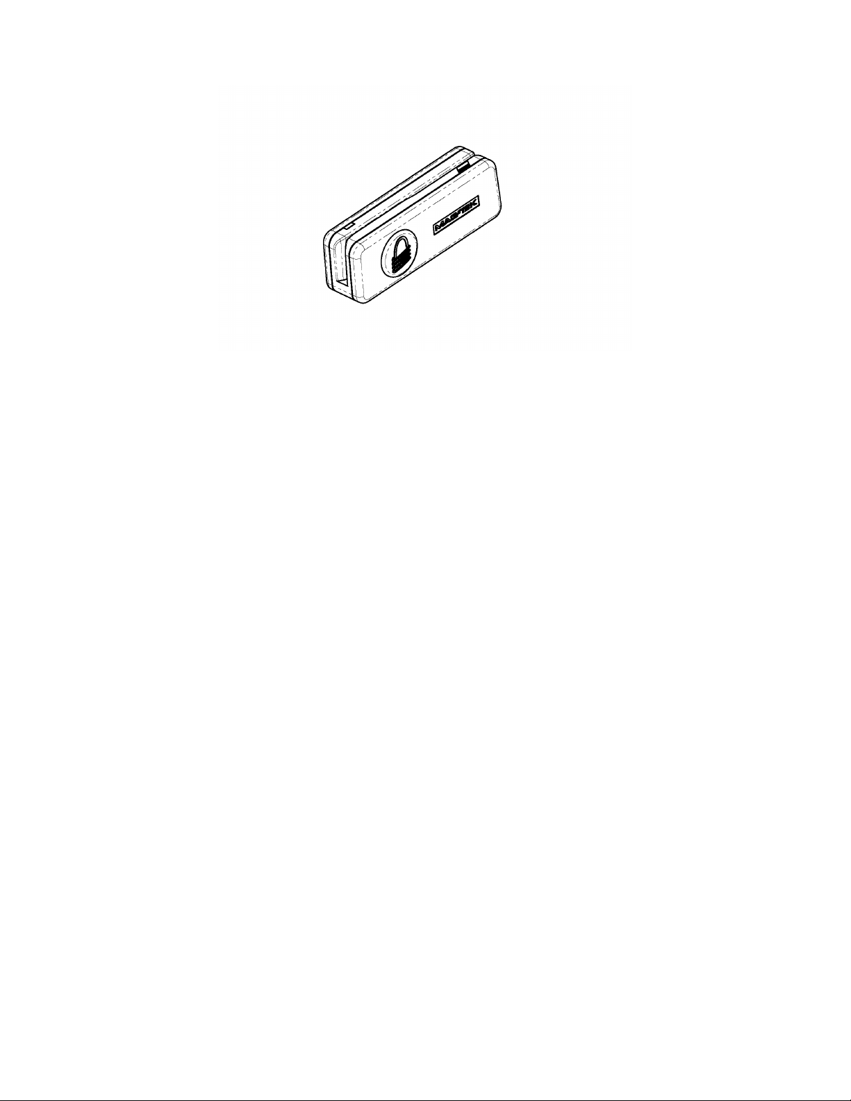
Figure 1-1. Bluetooth MagneSafe Swipe Reader
viii
Page 9

SECTION 1. FEATURES AND SPECIFICATIONS
The Bluetooth MagneSafe Swipe Reader is a compact, handheld magneti c st ri pe card read er that
conforms to ISO standards. In addition to reading multiple tracks of data from a card, this
Reader also includes MagnePrint technology and data encryption. The MagnePrint data will be
included with the track data on each transaction. In order to maximize card security, this Reader
incorporates data encryption to protect the card contents and the MagnePrint information. The
Reader is compatible with any device having a host Bluetooth interface. A card is read by
sliding it, stripe down and facing away from the LED side, through the slot either forward or
backward.
An LED (Light Emitting Diode) indicator on the Reader panel provides the operator with
continuous status of the Reader operations.
When a card is swiped through the Reader, the track data and MagnePrint information will be
TDEA (Triple Data Encryption Algorithm, aka Triple DES) encrypted using DUKPT (Derived
Unique Key Per Transaction) key management. This method of key management uses a base
derivation key to encrypt a key serial number that produces an initial encryption key which is
injected into the Reader prior to deployment. After each transaction, the encryption key is
modified per the DUKPT algorithm so that each transaction uses a unique key. Thus, the data
will be encrypted with a different encryption key for each transaction.
1
Page 10

Bluetooth MagneSafe V5 Swipe Reader
Part
Number
FEATURES
Major features of the Bluetooth Swipe Reader are as follows:
• Powered by a rechargeable battery; recharging can be provided via a standard USB cable (for
recharging only)
• Compatible with any device that supports Bluetooth virtual serial port profile (SPP)
• Bi-directional card reading
• Reads encoded data that meets ANSI/ISO/AAMVA standards and some custom formats such
as ISO track 1 format on track 2 or 3
• Reads up to three tracks of card data
• Red/Green/Amber LED for status
• Non-volatile memory for property storage
• Supplies 54 byte MagnePrint™ value
• Contains a unique, non-changeable device serial number which allows tracking each reader
• Encrypts all track data and the MagnePrint value
• Provides clear text confirmation data including card holder’s name, expiration date, and a
portion of the PAN as part of the Masked Track Data
• Mutual Authentication Mode for use with Magensa®
HARDWARE CONFIGURATION
The hardware configuration is as follows:
Part Number Tracks Style Interface Cable
21073021 1, 2, 3 BT90 Bluetooth N/R*
* No cable is required to operate the reader but one of the
cables listed below can be used to charge the battery.
ACCESSORIES
The accessories are as follows:
Description Notes
21051515 USB-A TO USB-Mini-B Gray, 750mm Cable For battery charging Bluetooth readers
21051516 USB-A TO USB-Mini-B Gray, 1200mm Coiled Cable For battery charging Bluetooth readers
51300010 Bluetooth USB 2.0 Adapter For interface to PC
REFERENCE DOCUMENTS
ANS X9.24-2004 Retail Financial Services Symmetric Key Management Part 1: Using
Symmetric Techniques
2
Page 11

Section 1. Features and Specifications
Reference Standards
ISO 7810 and ISO 7811; AAMVA*
Power Input
USB port or 5 VDC for battery charging
Time to Charge Battery
About 4.5 hours (from a fully discharged state)
Recording Method
Two-frequency coherent phase (F2F)
Message Format
ASCII
Card Speed
4 to 60 ips (10.1 to 152.4 cm/s)
Card Swipes per Full Charge
Over 500 swipes
ELECTRICAL
Current
100mA maximum during charge
MECHANICAL – BT90 Bluetooth
Length 3.49” (88.65mm)
Height 1.17” (29.72mm)
Weight
1.4 oz. (39.7 gr)
Cable length
n/a
Connector
USB Mini B 5-pin
ENVIRONMENTAL
Temperature
0 °C to 45 °C ((32 °F to 113 °F)
-20 °C to 60 °C (-4 °F to 140 °F)
Humidity
Operating
10% to 90% noncondensing
Storage
10% to 90% noncondensing
SPECIFICATIONS
Table 1-2 lists the specifications for the Bluetooth MagneSafe Reader. Figure 1-2 shows the
dimensions of the Reader.
Table 1-2. Specifications
Dimensions
Operating
Storage
* ISO (International Standards Organization) and AAMVA (American Association of Motor
Vehicle Administrators ).
Width 0.90” (22.86mm)
3
Page 12

Bluetooth MagneSafe V5 Swipe Reader
4
Page 13

SECTION 2. INSTALLATION
This section describes the cable connection and the Windows setup.
BLUETOOTH CONNECTION
On hosts with the Windows operating system, the Bluetooth reader appears as a virtual COM
port. Use the Windows Bluetooth installation utility or, if using another Bluetooth adapter,
follow the directions for that device.
See Appendix B or Appendix C for connection information.
5
Page 14

Bluetooth MagneSafe V5 Swipe Reader
6
Page 15

SECTION 3. OPERATION
ACTIVE INTERFACE
This reader communicates either via the Bluetooth interface or via the USB interface. When it
first powers up, if the USB cable is attached, it is receptive to commands on both interfaces.
Once it receives a command on one interface, that interface becomes the Active Interface and the
other interface is disabled. The Active Interface stays active until the reader is disconnected
from the USB cable or a Relinquis h Interfac e command is received. A Relinquish Interface
command causes both interfaces to be receptive to commands again.
If the reader is connected to a USB cable and the Active Interface is Bluetooth, any event that
would cause the reader to power down if it were not connected to the USB cable will have the
same effect as a Relinquish Interface command.
The intention here is to allow the user to communicate with the reader using whichever interface
is convenient while giving the user a method to enable the other interface at any time. For a
more detailed description of the USB interface, please refer to the USB MagneSafe V5
Swipe and Insert Reader Technical Reference Manual (99875388).
USER SWITCH
The User Switch, or Power Switch, is located on the side of the reader. Pressing the User Switch
when the reader is off will turn the reader on. The reader will stay on for a predetermined
amount of time (the default is 120 seconds) or until the completion of a card read transaction.
Pressing the User Switch briefly when the reader is on will extend the Activity Timer to its full
period, avoiding having the reader turn off due to inactivity.
If the power is already on, pressing the User Switch and holding it for three seconds will turn the
reader off.
LED INDICATOR
The LED indicator will be either off, red, green, or amber. When the reader is not powered, the
LED will be off.
When the Bluetooth reader is first turned on, the LED will flash amber and then go to solid green
unless the battery power is too low, in which case it will be red for two seconds then turn solid
green. When the reader shows a solid green, the reader is either awaiting Authentication (if
configured to require Authentication), or armed to read (if configured NOT to require
Authentication). When the Bluetooth reader is attached to a USB cable or other 5 volt power
source, the battery will begin charging. The LED will slowly blink amber while the battery is
charging and then turn solid amber when the battery is fully charged.
If enabled to operate with authentication (Security Level 4) and when the host completes
Authentication successfully, the LED will blink green; the reader is now armed to read a card. If
the host fails an Authentication sequence, the LED will turn solid red and stay red until either the
host completes Authentication successfully or the reader is powered down.
7
Page 16

Bluetooth MagneSafe V5 Swipe Reader
When a card is being swiped, the LED will turn off temporarily until the swipe is completed. If
there are no errors after decoding the card data, then the LED will turn green for approximately
two seconds to indicate a successful read and remain green for two seconds to indicate a
successful read and then turns off as the reader powers down.. If there are any errors after
decoding the card data, the LED will turn red for approximately two seconds to indicate that an
error occurred and then turn solid green to indicate that the card can be swiped again for another
try; the retries can go on indefinitely until a good read or until power goes off.
After a card swipe, when data should be transmitted on the Bluetooth connection, if the
connection is not available, the green LED will blink rapidly (10 times a second) until the
connection becomes available (when data is transmitted), the user holds the user switch down for
three seconds, the reader times out, or the battery power is too low. If the connection is
established the data is transmitted and the LED goes green or red to indicate transmission of
good or bad data.
CARD READ
A card may be swiped through the Reader slot when the LED is solid green or flashing green.
The magnetic stripe must face toward the head (as indicated by a card image on the top of the
reader) and may be swiped in either direction. If there is data encoded on the card, the reader
will attempt to read the data, encrypt it, and then send the encrypted results to the host. After the
results are sent to the host, the reader will automatically turn off.
READER STATES
This reader may be operated so that it requires Mutual Authentication with a Host in order to
transmit card data to the Host. When this mode of operation is required, the application software
(not necessarily the Authenticating Host) may need to know the state of the reader at any given
moment. This can be done using the Get Reader State Command. The application may retrieve
this state at any time to get a clear definition of the reader’s operation at any given moment.
For convenience, this manual refers to states with the notation State:Antecedent (e.g.,
WaitActAuth:BadSwipe). State definitions can be found at the definition of the Get Reader
State Command.
In most cases, the application could also track the state by inference. As the application interacts
with the reader, most state transitions are marked by commands and responses exchanged with
the reader. The exception to this concept is the transition from WaitActRply:x to
WaitActAuth:TOAuth. This state transition occurs as the result of a timeout and the transition is
not reported to the Host. As the reader was waiting for the Host to send the Activation
Challenge Reply command and the Host set the time limit that the reader should wait, the Host
should be aware that a timeout could occur. If the reader does time out and the Host sends the
Activation Challenge Reply command, the reader will return RC = 07 (Sequence error).
8
Page 17

Section 3. Operation
Examples of Host/Application/Reader interaction and state transitions:
Example 1 – Power Up followed by Authentication and good swipe:
1. Reader Powers Up (State = WaitActAuth:PU). The application should send
the Get Reader State Command to discover the current state of the reader.
2. Host sends valid Activate Authenticated Mode command (State =>
WaitActRply:PU). Reader responds with RC = 0x00 inferring the transition
to the WaitActRply:PU state.
3. Host sends valid Activation Challenge Reply command (State =>
WaitSwipe:PU). Reader responds with RC = 0x00 inferring the transition to
the WaitSwipe:PU state.
4. User Swipes a card correctly (State => WaitActAuth:GoodSwipe). Reader
sends the card data to the Host inferring the transition to the
WaitActAuth:GoodSwipe state.
Example 2 – Reader times out waiting for swipe:
1. Reader waiting (State = WaitActAuth:GoodSwipe). This is after a good
swipe. The application may send the Get Reader State Command to discover
the current state of the reader.
2. Host sends valid Activate Authenticated Mode command (State =>
WaitActRply:GoodSwipe). Reader responds with RC = 0x00 inferring the
transition to the WaitActRply:GoodSwipe state.
3. Host sends valid Activation Challenge Reply command (State =>
WaitSwipe:GoodSwipe). Reader responds with RC = 0x00 inferring the
transition to the WaitSwipe:GoodSwipe state.
4. Timer expires (State => WaitActAuth:TOSwipe). Reader sends “card data” to
the Host with no data, just a report about the Time Out (see Reader
Encryption Status); the Host infers the transition to WaitActAuth:TOSwipe
state.
Example 3 – Host sends invalid Activation Challenge Reply command:
1. Reader Waiting (State = WaitActAuth:GoodSwipe). This is after a good
swipe. Application may send the Get Reader State Command to discover the
current state of the reader.
2. Host sends valid Activate Authenticated Mode command (State =>
WaitActRply:GoodSwipe). Reader responds with RC=0x00 inferring the
transition to the WaitActRply:GoodSwipe state.
3. Host sends invalid Activation Challenge Reply command (State =>
WaitActAuth:FailAuth). Reader responds with RC = 0x02 or 0x04 inferring
the transition to the WaitActAuth:FailAuth state.
9
Page 18

Bluetooth MagneSafe V5 Swipe Reader
Example 4 – Host waits too long sending the Activation Challenge Reply command:
1. Reader Waiting (State = WaitActAuth:GoodSwipe). This is after a good
swipe. Application may send the Get Reader State Command to discover the
current state of the reader.
2. Host sends valid Activate Authenticated Mode command (State =>
WaitActRply:GoodSwipe). Reader responds with RC=0x00 inferring the
transition to the WaitActRply:GoodSwipe state.
3. Reader times out waiting for Host to send Activation Challenge Reply
command (State => WaitActAuth:TOAuth). Host doesn’t know because the
reader cannot/does not send any message.
4. Host finally sends Activation Challenge Reply command (State remains
WaitActAuth:TOAuth). Reader responds with RC=0x07 inferring the
previous transition to WaitActAuth:TOAuth state.
CHARGING THE BLUETOOTH READER BATTERY
As mentioned above (LED Indicator), the Bluetooth reader may indicate low battery at power up.
The first time this happens there will probably be sufficient battery available for several more
card swipes, but the battery should be charged soon. If the low battery warning is ignored and
the battery gets too low, the reader will refuse to power up until it has been charged.
Charge the reader by connecting it to any USB port on a running system or a compatible 5VDC
source. For best results, allow the battery to charge fully (until the LED goes to steady amber)
before using the reader again.
10
Page 19

SECTION 4. SECURITY
This reader is a secure reader. Security features include:
• Supplies 54 byte MagnePrint value
• Includes Device Serial Number
• Encrypts all track data and the MagnePrint value
• Provides clear text confirmation data including card holder’s name, expiration date, and a
portion of the PAN as part of the Masked Track Data
• Supports Mutual Authentication Mode for use with Magensa
• Offers selectable levels of Security
The reader supports two Security Levels. The Security Level can be increased by command, but
can never be decreased.
SECURITY LEVEL 3
Security Level 3 enables encryption of track data, MagnePrint data, and the Session ID.
MagnePrint data is always included and it is always encrypted. The format for the data is
detailed later in this document. At Security Level 3, many commands require security—most
notably, the Set Property command. Transition to Security Level 4 requires security.
SECURITY LEVEL 4
When the reader is at Security Level 4, a correctly executed Authentication Sequence is required
before the reader will emit data from a card swipe. Correctly executing the Authentication
Sequence also causes the Green LED to blink, alerting the user to the fact that the reader is being
controlled by a Host with knowledge of the keys—that is, an Authentic Host.
Commands that require security must be sent with a four byte Message Authentication Code
(MAC) appended to the end. The MAC is calculated as specified in ANSI X9.24 Part 1 – 2004,
Annex A. Note that data supplied to the MAC algorithm should NOT be converted to the
ASCII-Hex, rather it should be supplied in its raw binary form. The MAC key to be used is as
specified in the same document (“Request PIN Entry 2” bullet 2). Calculating the MAC requires
knowledge of the current DUKPT KSN, this could be retrieved using the Get DUKPT KSN and
Counter command. For each command processed successfully, the DUKPT Key is advanced.
11
Page 20

Bluetooth MagneSafe V5 Swipe Reader
Command
Level 3
Level 4
Get Property
Y
Y
Set Property
S
S
Reset
X*
X*
Get DUKPT SN and Counter
Y
Y
Set Session ID
Y
Y
Activate Authenticated Mode
Y
Y
Activation Challenge Reply
Y
Y
Deactivate Authenticated Mode
Y
Y
Get Reader State
Y
Y
Set Security Level
S
S
Get Encryption Counter
Y
Y
Relinquish Interface
Y
Y
Power Down
Y
Y
Get Battery Status
Y
Y
COMMANDS AND SECURITY LEVELS
The following table shows how security levels affect the various commands. “Y” means the
command can run. “N” means the command is prohibited. “S” means the command is protected
(requires MACing). “X” means other (notes to follow).
* The Reset command has special behavior. When an Authentication sequence has
failed, only a correctly MACed Reset command can be used to reset the reader. This
is to prevent a dictionary attack on the keys and to minimize a denial of service attack.
12
Page 21

SECTION 5. COMMUNICATIONS
CARD DATA
The details about how the card data and commands are structured follow later in this section.
Windows applications that communicate with this reader can be easily developed.
The reader will send only one swipe message per card swipe. When a card is swiped, the swipe
message will be sent even if the data is not decodable. If no data is detected on a track then
nothing will be transmitted for that track. If an error is detected on a track, the ASCII character
“E” will be sent in place of the track data to indicate an error. The LED will come on for about
two seconds and another swipe will be allowed. Data from the bad swipe is still transmitted.
A Swipe Message is composed of readable ASCII characters. It includes:
• Structural ASCII characters intended to give clues to the structure of the rest of the data.
• Simple ASCII fields that convey the ASCII representation of:
Masked Track Data
Device Serial Number
Format Code
• Binary fields that use sets of two ASCII characters representing hexadecimal digits to
convey the binary value of each byte in the field. The Binary fields are:
Reader Encryption Status
Encrypted Track Data
MagnePrint Status
Encrypted MagnePrint Data
Encrypted Session ID
DUKPT Key Serial Number
Clear Text CRC
Encrypted CRC
For the encrypted fields, the original binary bytes are encrypted using the DES CBC mode with
an Initialization Vector starting at all binary zeroes and the PIN Encryption Key associated with
the current DUKPT KSN. This is done in segments of 8 bytes. If the last segment of the original
data is less than eight bytes long (track data only), the last bytes of the block will be set to binary
zeroes before encrypting. When decrypting track data, the End Sentinel can be used to find the
actual end of the data (ignoring the final zeroes). Each byte of encrypted data is then converted
to two bytes of ASCII data representing the Hexadecimal value of the encrypted byte (many of
the encrypted bytes will not have values in the ASCII character range).
13
Page 22

Bluetooth MagneSafe V5 Swipe Reader
Label
Property
ID
P-Value
Description
Default
0x1E
P30
Pre card string
0 (0x00)
0x1F
P31
Post card string
0 (0x00)
0x20
P32
Pre track string
0 (0x00)
0x21
P33
Post track string
0 (0x00)
(0x0D)
0x23
P35
Programmable field separator
“|” (0x7C)
Tk1 SS
0x24
ISO/ABA start sentinel
“%” (0x25)
Tk2-SS
0x25
ISO/ABA 5-bit start sentinel
“;” (0x3B)
Tk3-SS
0x26
ISO/ABA start sentinel
“+” (0x2B)
Tk3-SS
AAMVA
AAMVA start sentinel
“#” (0x23)
1 start sentinel)
7 bit start sentinel (ISO/ABA Track
1 start sentinel)
“&”(0x26)
0x2B
0x2F
End Sentinel (for all tracks)
Track 3 Specific End Sentinel
“?” (0x3F)
“?” (0x3F)
The card data format for all programmable configuration options is as follows:
[P30]
[P32] [Tk1 SS] [Tk1 Masked Data] [ES ] [P3 3 ]
[P32] [Tk2 SS] [Tk2 Masked Data] [ES] [P3 3]
[P32] [Tk3 SS] [Tk3 Masked Data] [ES ] [P3 3 ]
[P31]
[P35] [Reader Encryption Status]
[P35] [Tk1 Encrypted Data (including TK1 SS and ES)]
[P35] [Tk2 Encrypted Data (including TK2 SS and ES)]
[P35] [Tk3 Encrypted Data (including TK3 SS and ES)]
[P35] [MagnePrint Status]
[P35] [Encrypted MagnePrint data]
[P35] [Device serial number]
[P35] [Encrypted Session ID]
[P35] [DUKPT serial number/counter]
[P35] [Encryption Counter] (optional, off by default)
[P35] [Clear Text CRC]
[P35] [Encrypted CRC]
[P35] [Format Code]
[P34]
The characters and fields are described in the list below. The Property ID (e.g., P13) is the
decimal value of the property ID in the command list (see Pre Card String).
Tk2-SS 7 bit 0x28
Tk3-SS 7 bit 0x29
Track 1, Track 2 and Track 3 Encrypted Data includes the Start and End Sentinel that were
decoded from the card.
14
ES
0x22 P34 Terminating string
0x27
0x2D
0x2E
7 bit start sentinel (ISO/ABA Track
Track 1 Specific End Sentinel
Track 2 Specific End Sentinel
C/R
“@”(0x40)
“?” (0x3F)
“?” (0x3F)
Page 23

Section 5. Communications
All fields with the format P## are programmable configuration property numbers. They are
described in detail later in this document.
Masked Track Data
If decodable track data exists for a given track, it is located in the Masked Track Data field that
corresponds to the track number. The length of each Masked Track Data field is fixed at 112
bytes, but the length of valid data in each field is determined by the Masked Track Data Length
field that corresponds to the track number. Masked Track Data located in positions greater than
indicated in the Masked Track Data Length field are undefined and should be ignored.
The Masked Track Data is decoded and converted to ASCII and then it is “masked.” The
Masked Track Data includes all data starting with the start sentinel and ending with the end
sentinel. Much of the data is “masked;” a specified mask character is sent instead of the actual
character read from the track. Which characters are masked depends on the format of the card.
Only ISO/ABA (Financial Cards with Format Code B) and AAMVA cards are selectively
masked; all other card types are either wholly masked or wholly clear. There is a separate
masking property for ISO/ABA cards and AAMVA cards. See the ISO Track Masking property
and the AAMVA Track Masking property for more information. Refer to Appendix E for a
description of how ISO/ABA and AAMVA cards are identified.
Each of these properties allows the application to specify masking details for the Primary
Account Number and Driver’s License / ID Number (DL/ID#), the masking character to be used,
and whether a correction should be applied to make the Mod 10 (Luhn algorithm) digit at the end
of the number be correct.
Track 1 Masked Data
This Simple ASCII field contains the Masked Track Data for track 1. All characters are
transmitted.
For an ISO/ABA card, the PAN is masked as follows:
The specified number of initial characters is sent unmasked. The specified number of
trailing characters is sent unmasked. If Mod 10 correction is specified, all but one of the
intermediate characters of the PAN are set to zero; one of them will be set such that the
last digit of the PAN calculates an accurate Mod 10 check of the rest of the PAN as
transmitted. If the Mod 10 correction is not specified, all of the intermediate characters
of the PAN are set to the specified mask character.
The Card Holder’s name and the Expiration Date are transmitted unmasked.
All Field Separators are sent unmasked.
All other characters are set to the specified mask character.
For an AAMVA card, the specified mask character is substituted for each of the characters read
from the card.
15
Page 24

Bluetooth MagneSafe V5 Swipe Reader
Track 2 Masked Data
This Simple ASCII field contains the Masked Track Data for track 2.
For an ISO/ABA card, the PAN is masked as follows:
• The specified number of initial characters is sent unmasked. The specified
number of trailing characters is sent unmasked. If Mod 10 correction is specified,
all but one of the intermediate characters of the PAN are set to zero; one of them
will be set such that the last digit of the PAN calculates an accurate Mod 10 check
of the rest of the PAN as transmitted. If the Mod 10 correction is not specified,
all of the intermediate characters of the PAN are set to the specified mask
character.
• The Expiration Date is transmitted unmasked.
• All Field Separators are sent unmasked.
• All other characters are set to the specified mask character.
For an AAMVA card, the DL/ID# is masked as follows:
• The specified number of initial characters are sent unmasked. The specified
number of trailing characters are sent unmasked. If Mod 10 correction is
specified, all but one of the intermediate characters of the DL/ID#PAN are set to
zero; one of them will be set such that the last digit of the DL/ID# calculates an
accurate Mod 10 check of the rest of the DL/ID# as transmitted. If the Mod 10
correction is not specified, all of the intermediate characters of the DL/ID# are set
to the specified mask character.
• The Expiration Date and Birth Date are transmitted unmasked.
• All other characters are set to the specified mask character.
Track 3 Masked Data
This Simple ASCII field contains the Masked Track Data for track 3.
For an ISO card, the PAN is masked as follows:
• The specified number of initial characters are sent unmasked. The specified
number of trailing characters are sent unmasked. If Mod 10 correction is
specified, all but one of the intermediate characters of the PAN are set to zero;
one of them will be set such that the last digit of the PAN calculates an accurate
Mod 10 check of the rest of the PAN as transmitted. If the Mod 10 correction is
not specified, all of the intermediate characters of the PAN are set to the specified
mask character.
• All Field Separators are sent unmasked.
• All other characters are set to the specified mask character.
For an AAMVA card, the specified mask character is substituted for each of the characters read
from the card.
16
Page 25

Section 5. Communications
Reader Encryption Status
This two byte Binary field contains the Encryption Status. The Reader Encryption Status is sent
in big endian byte order. Byte 1 is the least significant byte. Byte 1 LSB is status bit 0. Byte 2
MSB is status bit 15. The Reader Encryption status is defined as follows:
Bit 0 = DUKPT Keys exhausted
Bit 1 = Initial DUKPT key Injected
Bit 2 = Encryption Enabled
Bit 3 = Authentication Required
Bit 4 = Timed Out waiting for user to swipe card
Bits 5–7 = Unassigned (always set to Zero)
Bit 8 = Encryption Counter Expired
Bits 9–15 = Unassigned (always set to Zero)
Notes:
1. Encryption will only be performed when Encryption Enabled and Initial DUKPT key
Injected are set. Otherwise, data that are normally encrypted are sent in the clear in
ASCII HEX format; the DUKPT Serial Number/counter will not be sent.
2. When DUKPT Keys Exhausted is set, the reader will no longer read cards and after a
card swipe, the reader response will be sent as follows:
[P30]
[P31]
[P35] [Reader Encryption Status]
[P35]
[P35]
[P35]
[P35]
[P35]
[P35] [Device serial number]
[P35] [Encrypted Session ID]
[P35] [DUKPT serial number/counter]
[P35] [Encryption Counter] (optional, off by default)
[P35] [Clear Text CRC]
[P35] [Encrypted CRC]
[P35] [Format Code]
[P34]
Encrypted Track Data
If decodable track data exists for a given track, it is located in the Track x Encrypted Data field
that corresponds to the track number. The length of each Encrypted Data field is fixed at 112
bytes, but the length of valid data in each field is determined by the corresponding Encrypted
Data Length field that corresponds to the track number. Data located in positions greater than
the encrypted track data length field indicates are undefined and should be ignored. The HID
specification requires that reports be fixed in size, but the number of bytes encoded on a card
may vary. Therefore, the Input Report always contains the maximum amount of bytes that can
be encoded on the card and the number of valid bytes in each track is indicated by the Encrypted
Data Length field.
17
Page 26

Bluetooth MagneSafe V5 Swipe Reader
Nibble 1 2 3 4 5 6 7 8
Value A 1 0 5 0 0 0 0
Bit 7 6 5 4 3 2 1 0
15
14
13
12
11
10 9 8
23
22
21
20
19
18
17
16
31
30
29
28
27
26
25
24
Value
1 0 1 0 0 0 0 1 0 0 0 0 0 1 0 1 0 0 0 0 0 0 0 0 0 0 0 0 0 0 0
0
Usage*
R R R R R R R M R R R R R R R R 0 0 D 0 F L N S 0 0 0 0 0 0 0
0
The encrypted data from each track is decoded and converted to ASCII, and then it is encrypted.
The encrypted track data includes all data starting with the start sentinel and ending with the end
sentinel. The encryption begins with the first 8 bytes of the clear text track data. The 8-byte
result of this encryption is placed in the Encrypted Data buffer for the corresponding track. The
process continues using the CBC (Cipher Block Chaining) method with the encrypted 8 bytes
XORed with the next 8 bytes of clear text. That result is placed in next 8 bytes of the Encrypted
Data buffer and the process continues until all clear text bytes have been encrypted. If the final
block of clear text contains fewer than 8 bytes, it is padded with binary zeros to fill up the 8
bytes. After this final clear text block is XORed with the prior 8 bytes of encrypted data, it is
encrypted and placed in the Encrypted Data buffer. No Initial Vector is used in the process.
Decrypting the data must be done in 8 byte blocks, ignoring any final unused bytes in the last
block. See Appendix A for more information.
Track 1 Encrypted Data
This Binary field contains the encrypted track data for track 1.
Track 2 Encrypted Data
This Binary field contains the encrypted track data for track 2.
Track 3 Encrypted Data
This Binary field contains the encrypted track data for track 3.
MagnePrint Status
This Binary field represents 32 bits of MagnePrint status information. Each character represents
4 bits (hexadecimal notation). For example, suppose the characters are: “A1050000”:
18
* Usage Legend:
• D = Direction
• F = Too Fast
• L = Too Slow
• M = MagnePrint capable
• N = Too Noisy
• R = Revision
• S = Status
Page 27

Section 5. Communications
This four-byte field contains the MagnePrint status. The MagnePrint status is in little endian
byte order. Byte 1 is the least significant byte. Byte 1 LSB is status bit 0. Byte 4 MSB is status
bit 31. MagnePrint status is defined as follows:
Bit 0 = This is a MagnePrint-capable product (usage M)
Bits 1-15 = Product revision & mode (usage R)
Bit 16 = STATUS-only state (usage S)
Bit 17 = Noise too high or “move me” away from the noise source (used
only in STATUS) (usage N)
Bit 18 = Swipe too slow (usage L)
Bit 19 = Swipe too fast (usage F)
Bit 20 = Unassigned (always set to Zero)
Bit 21 = Actual Card Swipe Direction (0 = Forward, 1 = Reverse) (usage D)
Bits 22-31 = Unassigned (always set to Zero)
If the Enable/Disable MagnePrint property is set to disable MagnePrint, this field will not be
sent.
Encrypted MagnePrint Data
This 56-byte Binary field contains the MagnePrint data. Only the number of bytes specified in
the MagnePrint data length field are valid. The least significant bit of the first byte of data in this
field corresponds to the first bit of MagnePrint data. If the Enable/Disable MagnePrint property
is set to disable MagnePrint, this field will not be sent.
Device Serial Number
This 16-byte ASCII field contains the device serial number. The device serial number is a NUL
(zero) terminated string. So the maximum length of the device serial number, not including the
null terminator, is 15 bytes. This device serial number can also be retrieved and set with the
device serial number property explained in the property section of this document. This field is
stored in non-volatile memory, so it will persist when the unit is power cycled.
Encrypted Session ID
This 8-byte Binary field contains the encrypted version of the current Session ID. Its primary
purpose is to prevent replays. After a card is read, this property will be encrypted, along with the
card data, and supplied as part of the transaction message. The clear text version of this will
never be transmitted. To avoid replay, the application sets the Session ID property before a
transaction and verifies that the Encrypted Session ID returned with card data decrypts to the
value set.
DUKPT Key Serial Number
This 10 byte Binary field contains the DUKPT Key Serial Number used to encrypt the encrypted
fields in this message. This 80-bit field includes the Initial Key Serial Number in the leftmost 59
bits and a value for the Encryption Counter in the rightmost 21 bits. If no keys are loaded, all
bytes will have the value 0x00.
Encryption Counter
This 3-byte field contains the value of the Encryption Counter at the end of this transaction. See
the Get Encryption Counter command for more information.
19
Page 28

Bluetooth MagneSafe V5 Swipe Reader
Clear Text CRC
This two byte Binary field contains a clear text version of a Cyclical Redundancy Check (CRC)
(least significant byte sent first). It provides a CRC of all characters sent prior to this CRC. The
CRC is converted to four characters of ASCII before being sent. The application may calculate a
CRC from the data received prior to this CRC and compare it to the CRC received. If they are
the same, the application can have high confidence that all the data was received correctly. The
Send Clear Text CRC property controls whether this field is sent. If the property is True, the
CRC is sent, if it is False, the CRC is not sent. The default state for this property is True.
Encrypted CRC
This 8-byte Binary field contains an encrypted version of a Cyclical Redundancy Check (CRC).
It provides a CRC of all characters sent prior to this CRC. The CRC is converted to 16
characters of ASCII before being sent. After the receiver decrypts the message, the CRC is
contained in the first 2 bytes of the message, all other bytes are meaningless. The application
may calculate a CRC from the data received prior to this CRC and compare it to the CRC
received. If they are the same, the application can have high confidence that all the data was
received correctly. The CRC Flag property controls whether this field is sent.
Format Code
This 4-character ASCII field contains the Format Code. The purpose of the Format Code is to
allow the receiver of this message to know how to find the different fields in the message. The
default Format Code for this reader is “0000”. If any of the properties that affect the format of
the message are changed, the first character of the Format Code will automatically change to a
“1”. The application may change the final three characters, but making such a change will
automatically cause the first character to a “1”.
PROGRAMMABLE CONFIGURATION OPTIONS
This reader has a number of programmable configuration properties. These properties are stored
in non-volatile memory. These properties can be configured at the factory or by the end user
using a program supplied by MagTek. Programming these parameters requires low level
communications with the reader. Details on how to communicate with the reader to change
programmable configuration properties follows in the next few sections. These details are
included as a reference only. Most users will not need to know these details because the reader
will be configured at the factory or by a program supplied by MagTek. Most users may want to
skip over the next few sections on low level communications and continue with the details of the
configuration properties.
COMMANDS
Most host applications do not need to send commands to the reader. Most host applications only
need to obtain card data from the reader as described previously in this section. This section of
the manual can be ignored by anyone who does not need to send commands to the reader.
Command requests and responses are sent to and received from the reader using command
strings. Command requests are sent to the reader via a serial port. The response to a command
is retrieved from the corresponding serial port.
20
Page 29

Section 5. Communications
Byte
Usage
0
Command Number
1
Data Length
2 – 23
Data
Byte
Usage
0
Result Code
1
Data Length
2 – 23
Data
Each command and response is composed of a series of readable ASCII characters followed by
the ASCII character CR (0x0D). The ASCII characters preceding the CR are the message.
There should always be an even number of characters and they should contain only the
characters 0123456789ABCDEF. The receiver will combine two successive ASCII characters
from the message to form one “byte” (see the descriptions of the commands) which may have
any value from 0x00 to 0xFF.
The following table shows the structure of a command message:
The following table shows the structure of a response to a command.
PRIVILEGED COMMANDS
Some commands are, for security purposes, privileged. Those commands are:
1. Set Property
2. Reset Device*
3. Set Security Level†
* The Reset Device command is usually not Privileged. The exception is during a sequence
to Activate the Authenticated Mode. During this sequence the Reset Device command is
Privileged to avoid a hacker using this sequence to exhaust DUKPT keys rendering the
reader unusable.
† The Set Security Level command is Privileged when it is being used to set the Security
Level. It is not Privileged when it is being used to Get the Security Level.
When the Security Level is set to higher than 2 (see the Security section), the privileged
commands must be MACed in order to be accepted. If a MAC is required but not present or
incorrect, RC = 07 will be returned.
21
Page 30

Bluetooth MagneSafe V5 Swipe Reader
Value
(Hex)
00
Get Property
Gets a property from the reader
01
Set Property
Sets a property in the reader
02
Reset Device
Resets the reader
09
Get DUKPT KSN
Reports DUKPT KSN and Counter
0A
Set Session ID
Sets the current Session ID
Activate Authenticated
Mode
Starts Activation of Authenticated Mode of
secure operation
Command
of secure operation
Deactivate Authenticated
Mode
Deactivates the Authenticated Mode of secure
operation
13
Reserved
14
Get Reader State
Gets the current state of the reader
15
Set Security Level
Sets or gets the current Security Level
Bluetooth or USB interface.
Powers down the MSR circuits (if running on
battery turns reader off).
29
Get Battery Status
Gets Charge Status of battery
Value (Hex)
Result Code
Description
00
Success
The command completed successfully.
01
Failure
The command failed.
The command failed due to a bad parameter or
command syntax error.
05
Delayed
The request is refused due to anti-hacking mode
07
Invalid Operation
Depends on context of command
COMMAND NUMBER
This one-byte field contains the value of the requested command number. The following table
lists all the existing commands:
Command Number Description
10
11
12
25 Relinquish Interface
28 Power Down MSR
Activation Challenge Reply
Completes the Activation of Authenticated Mode
Makes reader receptive to commands on either
DATA LENGTH
This one-byte field contains the length of the valid data contained in the Data field. For
example, a command with one byte of data would send 01 for this byte; a command with 18
bytes of data would send 12 for this byte.
DATA
This multi-byte field contains command data if any. Note that the maximum length of this field
is fixed at 60 bytes. Valid data should be placed in the field starting at offset 2.
RESULT CODE
This one-byte field contains the value of the result code. There are two types of result codes:
generic result codes and com man d-specific result codes. Generic result codes always have the
most significant bit set to zero. Generic result codes have the same meaning for all commands
and can be used by any command. Command-specific result codes always have the most
significant bit set to one. Command-specific result codes are defined by the command that uses
them. The same code can have different meanings for different commands. Command-specific
result codes are defined in the documentation for the command that uses them. Generic result
codes are defined in the following table.
02 Bad Parameter
22
Page 31

Section 5. Communications
Data Offset
Value
0
Property ID
Data Offset
Value
0 – n
Property Value
Data Offset
Value
0
Property ID
1 – n
Property Value
Value
(Hex)
00
SOFTWARE ID
The reader’s software identifier
03
DEVICE SERIAL NUM
Reader serial number
04
Reserved for future use
05
TRACK ID ENABLE
Track enable / ID enable
06
Reserved for future use
07
ISO Track Mask
Specifies Masking factors for ISO cards
08
AAMVA Track Mask
Specifies Masking factors for AAMVA cards
09-0A
Reserved for future use
Specifies minimum time reader will operate in the
absence of activity (used to conserve batt ery life)
0B-0C
Reserved for future use
0D
Bluetooth Disconnect Message
Message to be transmitted when reader disconnects
0E
Stay Powered After Swipe
Allows reader to stay powered after a good swipe
0F
Reserved for future use
10
Interface Type
Type of interface
GET AND SET PROPERTY COMMANDS
The Get Property command gets a property from the reader. The Get Property command
number is 00.
The Set Property command sets a property in the reader. The Set Property command number
is 01. For security purposes, this command is privileged. This command must be MACed in
order to be accepted.
The Get and Set Property command data fields for the requests and responses are structured as
follows:
Get Property Request Data:
Get Property Respons e Data:
Set Property Request Data:
Set Property Respo ns e Dat a:
None
The result codes for the Get and Set Property commands can be any of the codes listed in the
generic result code table. If the Set Property command gets a result code of 0x07, it means the
required MAC was absent or incorrect.
Property ID
Property ID is a one-byte field that contains a value that identifies the property. The following
table lists all the current property ID values:
Property Description
0B Activity Timeout Period
23
Page 32

Bluetooth MagneSafe V5 Swipe Reader
Value
(Hex)
11-13
Reserved for future use
14
Track Data Send Flags
Track data send flags
15
MP Flags
Enables sending of MagnePrint data
16-18
Reserved for future use
19
CRC FLAG
Enables/disables sending CRC
1A
SureSwipe Flag
Sends data in SureSwipe format without MagnePrint
1B-1D
Reserved for future use
1E
Pre Card String
Pre card string
1F
Post Card String
Post card string
20
Pre TK String
Pre track string
21
Post TK String
Post track string
22
Termination String
Terminating string
23
FS
Field Separator for additional data
24
SS TK1 ISO ABA
Start sentinel char for track 1 – ISO/ABA
25
SS TK2 ISO ABA
Start sentinel char for track 2 – ISO/ABA
26
SS TK3 ISO ABA
Start sentinel char for track 3 – ISO/ABA
27
SS TK3 AAMVA
Start sentinel char for track 3 - AAMVA
28
SS TK2 7BITS
Start sentinel char for track 2 – 7 bit data
29
SS TK3 7BITS
Start sentinel char for track 3 – 7 bit data
2A
Reserved for future use
2B
ES
End sentinel char for all tracks/formats
2C
Format Code
Defines the Format Code to be sent with the message
2D
ES Track 1
End sentinel char for track 1
2E
ES Track 2
End sentinel char for track 2
2F
ES Track 3
End sentinel char for track 3
30
Send Encryption Counter
Enables/disables sending of Encryption Counter
Financial format or the AAMVA format.
Send clear AAMVA card data
flag
Property Type
Description
Byte
This is a one-byte value. The valid values depend on the property.
String
This is a multiple byte ASCII string. Its length can range from zero
length of the string does not include a terminating NUL character.
Property Description
31 Mask “Other” Cards
34
Enables/disables masking of don’t meet the ISO
Enables/disables sending AAMVA data in the clear.
The Property Value is a multiple-byte field that contains the value of the property. The number
of bytes in this field depends on the type of property and the length of the property. The
following table lists all of the property types and describes them.
to a maximum length that depends on the property. The value and
Property Default Values
Each property specifies a default value. This is the firmware default value and may be changed
during the manufacturing or order fulfillment process to support the needs of specific clients.
SOFTWARE ID PROPERTY
Property ID: 0x00
Property Type: String
Length: Fixed at 11 bytes
Get Property: Yes
Set Property: No
24
Page 33
Section 5. Communications
Cmd Num
Data Len
Prp ID
00
01
00
Result Code
Data Len
Prp Value
00
0B
32 31 30 34 32 38 31 32 44 30 31
Cmd Num
Data Len
Prp ID
Prp Value
01
04
03
31 32 33
Result Code
Data Len
Data
00
00
Cmd Num
Data Len
Prp ID
00
01
03
Result Code
Data Len
Prp Value
00
03
31 32 33
Description: This is an 11 byte read-only property that identifies the software part number
and version for the reader. The first 8 bytes represent the part number and the
last 3 bytes represent the version. For example this string might be
“21042812D01”. Examples follow:
Example Get Software ID property Request (Hex):
Example Get Software ID property Response (Hex):
DEVICE SERIAL NUM PROPERTY
Property ID: 0x03
Property Type: String
Length: 0 – 15 bytes
Get Property: Yes
Set Property: Yes (Once only)
Default Value: The default value is no string with a length of zero.
Description: The value is an ASCII string that represents the reader serial number. This
string can be 0 – 15 bytes long. This property may be Set once only.
Attempts to Set the property again will fail with RC = 0x07 (Sequence Error).
This property is stored in non-volatile memory, so it will persist when the unit
is power cycled. When this property is changed, the unit must be reset (see
Command Number 2) or power cycled for these changes to take effect.
Example Set Device Serial Num property Request (Hex):
Example Set Device Serial Num property Response (Hex):
Example Get Device Serial Num property Request (Hex):
Example Get Device Serial Num property Response (Hex):
25
Page 34

Bluetooth MagneSafe V5 Swipe Reader
Cmd Num
Data Len
Prp ID
Prp Value
01
02
05
95
Result Code
Data Len
Data
00
00
Cmd Num
Data Len
Prp ID
00
01
05
Result Code
Data Len
Prp Value
00
01
95
TRACK ID ENABLE PROPERTY
Property ID: 0x05
Property Type: Byte
Length: 1 byte
Get Property: Yes
Set Property: Yes
Default Value: 0x95
Description: This property is defined as follows:
id 0 T3 T3 T2 T2 T1 T1
Id 0 – Decodes standard ISO/ABA cards only
1 – Decodes AAM VA an d 7-bit cards also
If this flag is set to 0, only tracks that conform to the ISO format allowed for that
track will be decoded. If the track cannot be decoded by the ISO method it will
be considered to be in error.
T# 00 – Track Disabled
01 – Track Enabled
10 – Track Enabled/Required (Error if blank)
This property is stored in non-volatile memory, so it will persist when the unit is
power cycled. When this property is changed, the unit must be reset (see
Command Number 2) or power cycled for these changes to take effect. To
properly power cycle this reader, it must be unplugged for at least 30 seconds.
Example Set Track ID Enable property Request (Hex):
Example Set Track ID Enable property Response (Hex):
Example Get Track ID Enable property Request (Hex):
Example Get Track ID Enable property Response (Hex):
ISO TRACK MASK PROPERTY
Property ID: 0x07
Property Type: String
Length: 6 bytes
Get Property: Yes
Set Property: Yes
Default Value: ”04040Y”
26
Page 35

Section 5. Communications
Description: This property specifies the factors for masking data on ISO type cards:
• The first two bytes specify how many of the leading characters of the PAN
should be sent unmasked. The range of masking is from “00” to “99.”
• The next two bytes specify how many of the trailing characters of the PAN
should be sent unmasked. The range of masking is from “00” to “99.”
• The fifth byte specifies which character should be used for masking. If this
byte contains the uppercase letter ‘V’, the following rules apply:
o The character used for masking the PAN will be ‘0’
o All data after the PAN will be sent without masking
• The sixth byte specifies whether the Mod 10 Correction should be applied to
the PAN. “Y” means Yes, the Mod 10 Correction will be applied. “N” means
No, the Mod 10 will not be applied. (This option is only effective if the
masking character is “0”.)
This property is stored in non-volatile memory, so it will persist when the unit
is power cycled. When this property is changed, the unit must be reset (see
Command Number 2) or power cycled for these changes to take effect.
AAMVA TRACK MASK PROPERTY
Property ID: 0x08
Property Type: String
Length: 6 bytes
Get Property: Yes
Set Property: Yes
Default Value: ”04040Y”
Description: This property specifies the factors for masking data on AAMVA type cards:
• The first two bytes specify how many of the leading characters of the Driver’s
License/ID Number (DL/ID#) should be sent unmasked. The range of
masking is from “00” to “99.”
• The next two bytes specify how many of the trailing characters of the DL/ID#
should be sent unmasked. The range of masking is from “00” to “99.”
• The fifth byte specifies which character should be used for masking. If this
byte contains the uppercase letter ‘V’, the following rules apply:
o The PAN will be masked according to the rules of this property
(the Send Clear AAMVA Card Data property is ignored)
o The character used for masking the PAN will be ‘0’
o All data after the PAN will be sent without masking
• The sixth byte specifies whether the Mod 10 Correction should be applied to
the DL/ID#. “Y” means Yes, the Mod 10 Correction will be applied. “N”
means No, the Mod 10 will not be applied. (This option is only effective if
the masking character is “0”.)
This property is stored in non-volatile memory, so it will persist when the unit
is power cycled. When this property is changed, the unit must be reset (see
Command Number 2) or power cycled for these changes to take effect.
27
Page 36

Bluetooth MagneSafe V5 Swipe Reader
ACTIVITY TIMEOUT PERIOD PROPERTY
Property ID: 0x0B
Property Type: Byte
Length: 1 byte
Get Property: Yes
Set Property: Yes
Default Value: 120 (0x78) seconds
Description: This property specifies, in seconds, the minimum amount of time a Bluetooth
reader will operate in the absence of activity. Activity is:
• Swiping and processing of a card.
• Receipt and processing of commands from a Host.
• Briefly pressing the User Switch
When the specified time passes without activity, the reader is powered down.
This property is stored in non-volatile memory, so it will persist when the unit
is power cycled. When this property is changed, the unit must be reset (see
Command Number 2) or power cycled for these changes to take effect.
BLUETOOTH DISCONNECT MESSAGE PROPERTY
Property ID: 0x0D
Property Type: String
Length: 7 bytes
Get Property: Yes
Set Property: Yes
Default Value: The default value is no string with a length of zero.
Description: This property specifies a string to be used as part of a Bluetooth Disconnect
Message. The message is intended to give the connected host application a
warning that the reader is disconnecting. The full disconnect message consists
of the specified string followed by the character ‘-‘ (hyphen), followed by a
single character Reason Code, followed by a Carriage Return (0x0D)
character. The possible Reason Codes are:
‘T’ = Timeout
‘U’ = User Switch
‘B’ = Battery Low
‘S’ = Card Swipe
‘R’ = Reset command
‘I’ = Interface changed
This property is stored in non-volatile memory, so it will persist when the unit
is power cycled. When this property is changed, the unit must be reset (see
Command Number 2) or power cycled for these changes to take effect.
28
Page 37

Section 5. Communications
Cmd Num
Data Len
Prp ID
00
01
10
Result Code
Data Len
Prp Value
00
01
03
STAY POWERED AFTER SWIPE PROPERTY
Property ID: 0x0E
Property Type: Byte
Length: 1 byte
Get Property: Yes
Set Property: Yes
Default Value: 0x00 (Don’t Stay Powered)
Description: This property controls whether the reader stays powered after a good swipe.
If the property value is 0x00 (the default), the reader powers down after a
good swipe.
If the property value is 0x01, the reader stays powered after a good swipe. In
this case, the reader may be powered down by the user pressing and holding
the User Switch or it will time out eventually.
This property is stored in non-volatile memory, so it will persist when the unit
is power cycled. When this property is changed, the unit must be reset (see
Command Number 2) or power cycled for these changes to take effect.
INTERFACE TYPE PROPERTY
Property ID: 0x10
Property Type: Byte
Length: 1 byte
Get Property: Yes
Set Property: No
Default Value: 3 (Indicates Bluetooth interface)
Description: The value is a byte that represents the reader’s interface type. It is always set
to 3 indicating this is a Bluetooth reader.
Example Get Interface Type property Request (Hex):
Example Get Interface Type property Response (Hex):
TRACK DATA SEND FLAGS PROPERTY
Property ID: 0x14
Property Type: Byte
Length: 1 byte
Get Property: Yes
Set Property: Yes
Default Value: 0x63
Description: This property is defined as follows:
ICL SS ES LRC 0 LC Er Er
29
Page 38

Bluetooth MagneSafe V5 Swipe Reader
ICL 0 – Changing the state of the caps lock key will not affect the case of the data
1 – Changing the state of the caps lock key will affect the case of the data
SS 0 – Don’t send Start Sentinel for each track
1 – Send Start Sentinel for each track
ES 0 – Don’t send End Sentinel for each track
1 – Send End Sentinel for each track
LRC 0 – Don’t send LRC for each track
1 – Send LRC for each track
Note that the LRC is the unmodified LRC from the track data. To verify the LRC
the track data needs to be converted back from ASCII to card data format and the
start sentinels that were modified to indicate the card encode type need to be
converted back to their original values.
LC 0 – Send card data as upper case
1 – Send card data as lower case
Er 0x – Don’t send track data if error
11 – Send ‘E’ for each track error
This property is stored in non-volatile memory, so it will persist when the unit is
power cycled. When this property is changed, the unit must be reset (see
Command Number 2) or power cycled for these changes to take effect.
MP FLAGS PROPERTY
Property ID: 0x15
Property Type: Byte
Length: 1 byte
Get Property: Yes
Set Property: Yes
Default Value: 0x00
Description: This property is defined as follows:
0 0 0 0 0 0 0 S
S 0 – MagnePrint Data will NOT be sent
1 – MagnePrint Data will be sent.
This property is used to designate whether or not the MagnePrint data is sent as
part of a message. Setting S to 1 causes the MagnePrint Status and Unencrypted
MagnePrint Data to be sent with each swipe. Setting S to 0 causes these fields to
be omitted from the data. When the fields are omitted, the Programmable Field
Separator that precedes each of these fields will also be omitted.
30
Page 39

Section 5. Communications
Cmd Num
Data Len
Prp ID
Prp Value
01
04
1E
31 32 33
This property is stored in non-volatile memory, so it will persist when the unit is
power cycled. When this property is changed, the unit must be reset (see
Command Number 2) or power cycled for these changes to take effect.
CRC FLAG PROPERTY
Property ID: 0x19
Property Type: Byte
Length: 1 byte
Get Property: Yes
Set Property: Yes
Default Value: 0x01
Description: This property is defined as follows:
0 0 0 0 0 0 E S
E 0 – The Encrypted CRC will NOT be sent
1 – The Encrypted CRC will be sent
S 0 – The Clear Text CRC will NOT be sent
1 – The Clear Text CRC will be sent
This property is used to designate whether or not the calculated CRC is sent as
part of a message. The default state of this property causes only the Clear Text
CRC to be sent. When the fields are omitted, the Programmable Field Separator
that precedes each of these fields will be sent anyhow.
This property is stored in non-volatile memory, so it will persist when the unit is
power cycled. When this property is changed, the unit must be reset (see
Command Number 2) or power cycled for these changes to take effect.
PRE CARD STRING PROPERTY
Property ID: 0x1E
Property Type: String
Length: 0 – 7 bytes
Get Property: Yes
Set Property: Yes
Default Value: The default value is no string with a length of zero.
Description: The value is an ASCII string that represents the reader’s pre card string. This
string can be 0 – 7 bytes long. This string is sent prior to all other card data.
This property is stored in non-volatile memory, so it will persist when the unit
is power cycled. When this property is changed, the unit must be reset (see
Command Number 2) or power cycled for these changes to take effect.
Example Set Pre Card String property Request (Hex):
31
Page 40
Bluetooth MagneSafe V5 Swipe Reader
Result Code
Data Len
Data
00
00
Cmd Num
Data Len
Prp ID
00
01
1E
Result Code
Data Len
Prp Value
00
03
31 32 33
Cmd Num
Data Len
Prp ID
Prp Value
01
04
1F
31 32 33
Result Code
Data Len
Data
00
00
Cmd Num
Data Len
Prp ID
00
01
1F
Result Code
Data Len
Prp Value
00
03
31 32 33
Example Set Pre Card String property Response (Hex):
Example Get Pre Card String property Request (Hex):
Example Get Pre Card String property Response (Hex):
POST CARD STRING PROPERTY
Property ID: 0x1F
Property Type: String
Length: 0 – 7 bytes
Get Property: Yes
Set Property: Yes
Default Value: The default value is no string with a length of zero.
Description: The value is an ASCII string that represents the reader’s post card string. This
string can be 0 – 7 bytes long. This string is sent after all other card data.
This property is stored in non-volatile memory, so it will persist when the unit
is power cycled. When this property is changed, the unit must be reset (see
Command Number 2) or power cycled for these changes to take effect.
Example Set Post Card String property Request (Hex):
Example Set Post Card String property Response (Hex):
Example Get Post Card String property Request (Hex):
Example Get Post Card String property Response (Hex):
32
Page 41

Section 5. Communications
Cmd Num
Data Len
Prp ID
Prp Value
01
04
20
31 32 33
Result Code
Data Len
Data
00
00
Cmd Num
Data Len
Prp ID
00
01
20
Result Code
Data Len
Prp Value
00
03
31 32 33
Cmd Num
Data Len
Prp ID
Prp Value
01
04
21
31 32 33
PRE TRACK STRING PROPERTY
Property ID: 0x20
Property Type: String
Length: 0-7 bytes
Get Property: Yes
Set Property: Yes
Default Value: No string with a length of zero.
Description: This string is sent prior to the data for each track. The string can be 0 – 7
bytes long. If the value is 0 no character is sent.
This property is stored in non-volatile memory, so it will persist when the unit
is power cycled. When this property is changed, the unit must be reset (see
Command Number 2) or power cycled for these changes to take effect.
Example Set Pre Track String property Request (Hex):
Example Set Pre Track String property Response (Hex):
Example Get Pre Track String property Request (Hex):
Example Get Pre Track String property Response (Hex):
POST TRACK STRING PROPERTY
Property ID: 0x21
Property Type: String
Length: 0-7 bytes
Get Property: Yes
Set Property: Yes
Default Value: No string with a length of zero
Description: This string is sent after the data for each track. The string can be 0 – 7 bytes
long. If the value is 0 no character is sent.
This property is stored in non-volatile memory, so it will persist when the unit
is power cycled. When this property is changed, the unit must be reset (see
Command Number 2) or power cycled for these changes to take effect.
Example Set Post Track String property Request (Hex):
33
Page 42

Bluetooth MagneSafe V5 Swipe Reader
Result Code
Data Len
Data
00
00
Cmd Num
Data Len
Prp ID
00
01
21
Result Code
Data Len
Prp Value
00
03
31 32 33
Example Set Post Track String property Response (Hex):
Example Get Post Track String property Request (Hex):
Example Get Post Track String property Response (Hex):
TERMINATION STRING PROPERTY
Property ID: 0x22
Property Type: String
Length: 0-7 bytes
Get Property: Yes
Set Property: Yes
Default Value: 0x0D (carriage return)
Description: This string is sent after the all the data for a transaction. The string can be 0 –
7 bytes long. If the value is 0 no character is sent.
This property is stored in non-volatile memory, so it will persist when the unit
is power cycled. When this property is changed, the unit must be reset (see
Command Number 2) or power cycled for these changes to take effect.
FS PROPERTY
Property ID: 0x23
Property Type: Byte
Length: 1 byte
Get Property: Yes
Set Property: Yes
Default Value: 0x7C (‘|’)
Description: This character is sent as the field separator to delimit additional data
(MagnePrint info, reader info, DUKPT info, etc.). If the value is 0 no
character is sent. If the value is in the range 1 – 127 then the equivalent
ASCII character will be sent.
This property is stored in non-volatile memory, so it will persist when the unit
is power cycled. When this property is changed, the unit must be reset (see
Command Number 2) or power cycled for these changes to take effect.
34
Page 43

Section 5. Communications
SS TK1 ISO ABA PROPERTY
Property ID: 0x24
Property Type: Byte
Length: 1 byte
Get Property: Yes
Set Property: Yes
Default Value: 0x25 (‘%’)
Description: This character is sent as the track 1 start sentinel for cards that have track 1
encoded in ISO/ABA format. If the value is 0 no character is sent. If the
value is in the range 1 – 127 then the equivalent ASCII character will be sent.
This property is stored in non-volatile memory, so it will persist when the unit
is power cycled. When this property is changed, the unit must be reset (see
Command Number 2) or power cycled for these changes to take effect.
SS TK2 ISO ABA PROPERTY
Property ID: 0x25
Property Type: Byte
Length: 1 byte
Get Property: Yes
Set Property: Yes
Default Value: 0x3B (‘;’)
Description: This character is sent as the track 2 start sentinel for cards that have track 2
encoded in ISO/ABA format. If the value is 0 no character is sent. If the
value is in the range 1 – 127 then the equivalent ASCII character will be sent.
This property is stored in non-volatile memory, so it will persist when the unit
is power cycled. When this property is changed, the unit must be reset (see
Command Number 2) or power cycled for these changes to take effect.
SS TK3 ISO ABA PROPERTY
Property ID: 0x26
Property Type: Byte
Length: 1 byte
Get Property: Yes
Set Property: Yes
Default Value: 0x2B (‘+’)
Description: This character is sent as the track 3 start sentinel for cards that have track 3
encoded in ISO/ABA format. If the value is 0 no character is sent. If the
value is in the range 1 – 127 then the equivalent ASCII character will be sent.
This property is stored in non-volatile memory, so it will persist when the unit
is power cycled. When this property is changed, the unit must be reset (see
Command Number 2) or power cycled for these changes to take effect.
35
Page 44

Bluetooth MagneSafe V5 Swipe Reader
SS TK3 AAMVA PROPERTY
Property ID: 0x27
Property Type: Byte
Length: 1 byte
Get Property: Yes
Set Property: Yes
Default Value: 0x23 (‘#’)
Description: This character is sent as the track 3 start sentinel for cards that have track 3
encoded in AAMVA format. If the value is 0 no character is sent. If the
value is in the range 1 – 127 then the equivalent ASCII character will be sent.
This property is stored in non-volatile memory, so it will persist when the unit
is power cycled. When this property is changed, the unit must be reset (see
Command Number 2) or power cycled for these changes to take effect.
SS TK2 7BITS PROPERTY
Property ID: 0x28
Property Type: Byte
Length: 1 byte
Get Property: Yes
Set Property: Yes
Default Value: 0x40 (‘@’)
Description: This character is sent as the track 2 start sentinel for cards that have track 2
encoded in 7 bits per character format. If the value is 0 no character is sent. If
the value is in the range 1 – 127 then the equivalent ASCII character will be
sent.
This property is stored in non-volatile memory, so it will persist when the unit
is power cycled. When this property is changed, the unit must be reset (see
Command Number 2) or power cycled for these changes to take effect.
SS TK3 7BITS PROPERTY
Property ID: 0x29
Property Type: Byte
Length: 1 byte
Get Property: Yes
Set Property: Yes
Default Value: 0x26 (‘&’)
Description: This character is sent as the track 3 start sentinel for cards that have track 3
encoded in 7 bits per character format. If the value is 0 no character is sent. If
the value is in the range 1 – 127 then the equivalent ASCII character will be
sent.
This property is stored in non-volatile memory, so it will persist when the unit
is power cycled. When this property is changed, the unit must be reset (see
Command Number 2) or power cycled for these changes to take effect.
36
Page 45

Section 5. Communications
ES PROPERTY
Property ID: 0x2B
Property Type: Byte
Length: 1 byte
Get Property: Yes
Set Property: Yes
Default Value: 0x3F (‘?’)
Description: This character is sent as the end sentinel for all tracks with any format. If the
value is 0 no character is sent. If the value is in the range 1 – 127 then the
equivalent ASCII character will be sent.
This property is stored in non-volatile memory, so it will persist when the unit
is power cycled. When this property is changed, the unit must be reset (see
Command Number 2) or power cycled for these changes to take effect.
FORMAT CODE PROPERTY
Property ID: 0x2C
Property Type: String
Length: 4 bytes
Get Property: Yes
Set Property: Yes
Default Value: “0000”
Description: This property is defined as follows:
This property specifies the Format Code that will be returned at the end of a
transmitted card swipe. The application sends four characters, but only the
last three will be set. The first character is reserved for MagTek use. A value
of ‘0’ in the first character means the Format Code is defined by MagTek. A
value of ‘1’ in the first character means the Format Code is user defined.
This property is stored in non-volatile memory, so it will persist when the unit
is power cycled. When this property is changed, the unit must be reset (see
Command Number 2) or power cycled for these changes to take effect.
ES TRACK 1 PROPERTY
Property ID: 0x2D
Property Type: Byte
Length: 1 byte
Get Property: Yes
Set Property: Yes
Default Value: 0xFF (use ES property)
Description: This character is sent as the end sentinel for track 1 with any format. If the
value is 0 no character is sent. If the value is in the range 1 – 127 then the
equivalent ASCII character will be sent. If the value is 0xFF then the value of
the ES property will be used instead of this property.
37
Page 46

Bluetooth MagneSafe V5 Swipe Reader
This property is stored in non-volatile memory, so it will persist when the unit
is power cycled. When this property is changed, the unit must be reset (see
Command Number 2) or power cycled for these changes to take effect.
ES TRACK 2 PROPERTY
Property ID: 0x2E
Property Type: Byte
Length: 1 byte
Get Property: Yes
Set Property: Yes
Default Value: 0xFF (use ES property)
Description: This character is sent as the end sentinel for track 2 with any format. If the
value is 0 no character is sent. If the value is in the range 1 – 127 then the
equivalent ASCII character will be sent. If the value is 0xFF then the value of
the ES property will be used instead of this property.
This property is stored in non-volatile memory, so it will persist when the unit
is power cycled. When this property is changed, the unit must be reset (see
Command Number 2) or power cycled for these changes to take effect.
ES TRACK 3 PROPERTY
Property ID: 0x2F
Property Type: Byte
Length: 1 byte
Get Property: Yes
Set Property: Yes
Default Value: 0xFF (use ES property)
Description: This character is sent as the end sentinel for track 3 with any format. If the
value is 0 no character is sent. If the value is in the range 1 – 127 then the
equivalent ASCII character will be sent. If the value is 0xFF then the value of
the ES property will be used instead of this property.
This property is stored in non-volatile memory, so it will persist when the unit
is power cycled. When this property is changed, the unit must be reset (see
Command Number 2) or power cycled for these changes to take effect.
SEND ENCRYPTION COUNTER
Property ID: 0x30
Property Type: Byte
Length: 1 byte
Get Property: Yes
Set Property: Yes
Default Value: 0x00 (don’t send Encryption Counter)
Description: This property is used to designate whether or not the Encryption Counter is
send as part of a keyboard message. If the property is set to 0x00, the
Encryption Counter is not sent, neither is a field separator sent. If the property
38
Page 47

Section 5. Communications
Cmd Num
Data Len
Prp ID
Data
01
06
34
01 xx xx xx xx *
is set to 0x01, the Encryption Counter is sent as the next field after the
DUKPT Serial Number in a swipe message.
NOTE: If this property is set to 0x01 and the Format Code is currently
“0001”, the Format Code will be changed to “0002”.
This property is stored in non-volatile memory, so it will persist when the unit
is power cycled. When this property is changed, the unit must be reset (see
Command Number 2) or power cycled for these changes to take effect.
MASK OTHER CARDS
Property ID: 0x31
Property Type: Byte
Length: 1 byte
Get Property: Yes
Set Property: Yes
Default Value: 0x00 (Don’t Mask Other cards)
Description: This property is used to designate whether or not the cards which do not
decode as ISO/ABA Financial cards or AAMVA Driver License cards should
be sent with their data masked or in the clear. The default state is to send the
data in the clear (0x00). If this property is set to 0x01, the track(s) will be sent
with a ”0” for each byte of encoded data read.
This property is stored in non-volatile memory, so it will persist when the unit
is power cycled. When this property is changed, the unit must be reset (see
Command Number 2) or power cycled for these changes to take effect.
SEND CLEAR AAMVA CARD DATA PROPERTY
Property ID: 0x34
Property Type: Byte
Length: 1 byte
Get Property: Yes
Set Property: Yes
Default Value: 0x00
Description: This character is used to control how to send out AAMVA card data when the
security level is above 2.
This property is stored in non-volatile memory, so it will persist when the unit
is power cycled. When this property is changed, the unit must be reset (see
Command Number 2) or power cycled for these changes to take effect.
0 – send out masked AAMVA card data
1 – send out clear AAMVA card data
Example Set Send Clear AAMVA Card Data property Request (Hex):
* where “xx xx xx xx” is the MAC.
39
Page 48
Bluetooth MagneSafe V5 Swipe Reader
Result Code
Data Len
Data
00
00
Cmd Num
Data Len
Prp ID
00
01
34
Result Code
Data Len
Data
00
01
01
Cmd Num
Data Len
Data
02
00
Result Code
Data Len
Data
00
00
Example Set Send Clear AAMVA Card Data property Response (Hex):
Example Get Send Clear AAMVA Card Data property Request (Hex):
Example Get Send Clear AAMVA Card Data property Response (Hex):
RESET DEVICE COMMAND
Command number: 0x02
Description: This command is used to reset the reader. This command can be used to
make previously changed properties take affect without having to power
cycle the reader. If communication is via the USB port, when the reader
resets, it automatically does a USB detach followed by an attach. After
the host sends this command to the reader it should close the USB port,
wait a few seconds for the operating system to handle the reader detach
followed by the attach, and then re-open the USB port before trying to
communicate further with the reader.
When an Authentication sequence has failed, only a correctly MACed
(See Section 2, Security) Reset command can be used to Reset the reader.
This prevents a dictionary attack on the on the keys and minimizes a
denial of service attack.
Note
When the reader begins an Authentication Sequence, the Reset command will not
be honored until after the Authentication Sequence has successfully completed,
the user swipes a card, or the unit is power cycled.
Data structure: No data is sent with this command
Result codes: 0x00 (Success)
0x01 (Failure)
0x07 (Incorrect MAC – Command not authorized)
Example Reset Device Request (Hex):
Example Reset Device Response (Hex):
DUKPT OPERATION
Since key loading is proprietary and performed at MagTek, there are no user commands to
support key injection.
40
Page 49
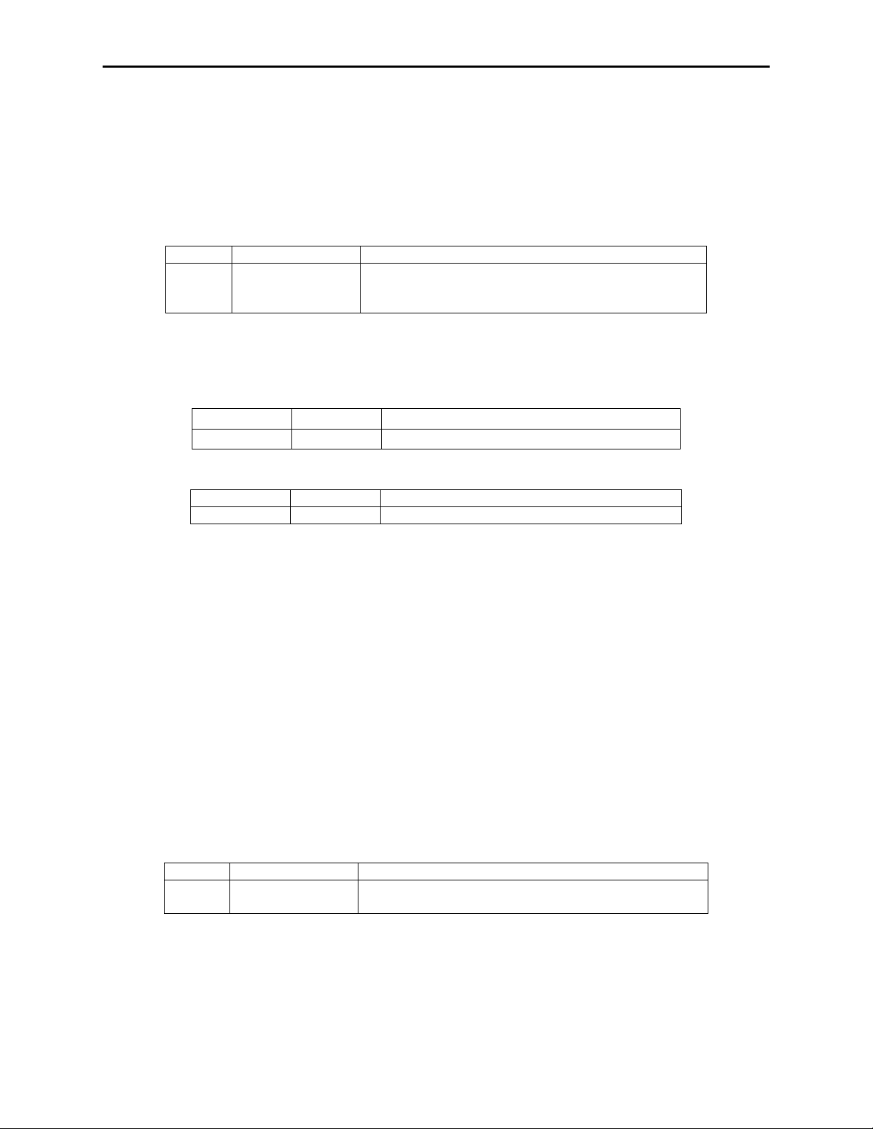
Section 5. Communications
Offset
Field Name
Description
Encryption Counter in the rightmost 21 bits.
Cmd Num
Data Len
Data
09
00
none
Result Code
Data Len
Data
00
0A
FFFF 9876 5432 10E0 0001
Offset
Field Name
Description
application wishes.
Get DUKPT KSN and Counter
Command number: 0x09
Description: This command is used to report the Key Serial Number and Encryption
Counter.
Data structure: No data is sent with this command.
Response Data:
0 Current Key
Serial Number
This eighty-bit field includes the Initial Key Serial
Number in the leftmost 59 bits and a value for the
Result codes: 0x00 (Success)
0x02 (Bad Parameters – the Request Data is not a correct length)
Example Get DUKPT KSN and Counter Request (Hex):
Example Get DUKPT KSN and Counter Response (Hex):
SET SESSION ID COMMAND
Command number: 0x0A
Description: This command is used to set the current Session ID. The new Session ID
stays in effect until one of the following occurs:
1. Another Set Session ID command is received.
2. The reader is powered down.
3. The reader is put into Suspend mode.
The Session ID is used by the host to uniquely identify the present
transaction. Its primary purpose is to prevent replays. After a card is read,
the Session ID will be encrypted, along with the card data, a supplied as
part of the transaction message. The clear text version of this will never
be transmitted.
Data structure:
Request Data:
0 New Session ID This eight-byte field may contain any value the
Response Data: None
Result codes: 0x00 (Success)
0x02 (Bad Parameters – the Request Data is not a correct length)
41
Page 50

Bluetooth MagneSafe V5 Swipe Reader
Cmd Num
Data Len
Data
0A
08
54 45 53 54 54 45 53 54
Result Code
Data Len
Data
00
00
Example Set Session ID Request (Hex):
Example Set Session ID Response (Hex):
ACTIVATE AUT H E N T I CATE D MODE CO MMAND
Command number: 0x10
Description: This command is used to activate the Authenticated Mode. When set to
Security Level 4, this reader will not transmit card data unless it is in the
Authenticated Mode. The Authenticated Mode may only be entered by
this command.
The application specifies a PreAuthentication Time Limit. This is the
maximum number of seconds the reader will wait for the Activation
Challenge Reply Command before timing out. If the supplied value is less
than 120 seconds, the reader will use 120 seconds. If the reader times out
waiting for the Activation Challenge Reply Command, the Authentication
attempt fails and anti-hacking behavior may be invoked.
The reader responds with two challenges (Challenge 1 and Challenge 2)
encrypted using a variant of the current DUKPT PIN Encryption Key
(Key XOR F0F0 F0F0 F0F0 F0F0 F0F0 F0F0 F0F0 F0F0). When
decrypted, Challenge 1 contains 6 bytes of random number (used in the
Activation Challenge Reply command) followed by the last two bytes of
the KSN. These last two bytes of the KSN may be compared with the last
two bytes of the clear text KSN sent in the message to authenticate the
reader. The application should complete the Activate Authentication
sequence using the Activation Challenge Reply command (see below).
The first two Activate Authenticated Mode commands may proceed
without any delay (one error is allowed with no anti-hacking
consequences). If a second Activate Authenticated Mode in a row fails,
the reader goes into anti-hacking behavior. This consists of an increasing
delay being enforced between Activate Authenticated Mode commands.
The first delay is 10 seconds, increasing by 10 seconds until a maximum
delay of 10 minutes is reached. The user may remove the reader from the
anti-hacking mode at any time by swiping any encoded magstripe card.
When the reader is in this anti-hacking mode it is NOT receptive to the
Reset Device command.
42
Page 51

Section 5. Communications
Offset
Field Name
Description
0
PreAuthentication
Time Limit (msb)
Most significant byte of the PreAuthentication Time
Limit.
1
PreAuthentication
Time Limit (lsb)
Least significant byte of the PreAuthentication Time
Limit.
Offset
Field Name
Description
0
Current Key
This eighty-bit field includes the Initial Key Serial
Encryption Counter in the rightmost 21 bits.
10
Challenge 1
This eight byte challenge may be used later in an
and to authenticate the reader as mentioned above.
18
Challenge 2
This eight byte challenge may be used later in a
below.
Cmd Num
Data Len
Data
10
00
Result Code
Data Len
Data
00
20
FFFF 0123 4567 8000 0003 9845 A48B 7ED3
C294 7987 5FD4 03FA 8543
Data structure:
Request Data:
Response Data:
Serial Number
Number in the leftmost 59 bits and a value for the
Activation Challenge Reply command shown below,
Deactivate Authenticated Mode command shown
Result codes: 0x00 (Success)
0x03 (Redundant – the reader is already in this mode)
0x05 (Delayed – the request is refused due to anti-hacking mode)
0x07 (Sequence Error – the current Security Level is too low)
0x80 (Encryption Counter Expired)
Example Activate Authenticated Mode Request (Hex):
Example Activate Authenticated Mode Response (Hex):
ACTIVATION CHALLENGE REPLY COMMAND
Command number: 0x11
Description: This command is used as the second part of an Activate Authentication
sequence. In this command, the application sends the first 6 bytes of
Challenge 1 (received in response to the Activate Authenticated Mode
command), two bytes of time information, and (optionally) an eight byte
Session ID encrypted with a variant of the current DUKPT PIN
Encryption Key (Key XOR 3C3C 3C3C 3C3C 3C3C 3C3C 3C3C 3C3C
3C3C).
The time information contains a count of the maximum number of seconds
the reader should remain in the Authenticated Mode. Regardless of the
value of this timer, a user card swipe in the Authenticated Mode ends the
Authenticated Mode. The maximum time allowed is 3600 seconds (one
hour). To get the full hour, use the value 0x0E10. To get the value of 3
minutes, use the value 0x012C. A value of zero forces the reader to stay
43
Page 52

Bluetooth MagneSafe V5 Swipe Reader
Offset
Field Name
Description
0
Response to
Six bytes of Challenge 1 plus two bytes of time as
the current DUKPT Key
8
Session ID
Optional eight byte Session ID encrypted by the
specified variant of the current DUKPT Key.
Cmd Num
Data Len
Data
11
08
8579 8275 2157 3495
Result Code
Data Len
Data
00
00
in the Authenticated Mode until a card swipe or power down occurs (no
timeout).
If the Session ID information is included and the command is successful,
it will change the Session ID in the reader.
If the reader decrypts the CR response correctly the Activate
Authenticated Mode has succeeded. If the reader can not decrypt the CR
command correctly the Activate Authenticated Mode has failed, the
DUKPT KSN advances.
Data structure:
Request Data: None
Challenge 1
outlined above, encrypted by the specified variant of
Response Data: None
Result codes: 0x00 (Success)
0x02 (Bad Parameters – the Request Data is not a correct length)
0x04 (Bad Data – the encrypted reply data could not be verified)
0x07 (Sequence – not expecting this command)
Example Activation Challenge Reply Request (Hex):
Example Activation Challenge Reply Response (Hex):
DEACTIVATE AUTHENTICATED MODE COMMAND
Command number: 0x12
Description: This command is used to exit the Authenticated Mode command. It can
be used to exit the mode with or without incrementing the DUKPT
transaction counter (lower 21 bits of the KSN). The application must send
the first 7 bytes of Challenge 2 (from the response to the Activate
Authenticated Mode command) and the Increment flag (0x00 indicates no
increment, 0x01 indicates increment of the KSN) encrypted with a variant
of the current DUKPT PIN Encryption Key (Key XOR 3C3C 3C3C 3C3C
3C3C 3C3C 3C3C 3C3C 3C3C).
44
Page 53

Section 5. Communications
Offset
Field Name
Description
0
Response to
Seven bytes of Challenge 2 plus one byte of
specified variant of the current DUKPT Key
Cmd Num
Data Len
Data
12
08
8579827521573495
Result Code
Data Len
Data
00
00
If the reader decrypts Challenge 2 successfully, it will exit the
Authenticated Mode and, depending on the Increment flag, may increment
the KSN.
If the reader cannot decrypt Challenge 2 successfully, it will stay in the
Authenticated Mode until either the time specified in the Activate
Authenticated Mode command passes or the user swipes a card. This
behavior is intended to discourage denial of service attacks. Exiting the
Authenticated Mode by timeout or card swipe always increments the
KSN; exiting Authenticated Mode by the Deactivate Authenticated Mode
command may increment the KSN.
Data structure:
Request Data:
Challenge 2
Increment flag as outlined above, encrypted by the
Response Data: None
Result codes: 0x00 (Success)
0x02 (Bad Parameters – the Request Data is not a correct length)
0x03 (Bad Data – the encrypted reply data could not be verified)
0x07 (Sequence – not expecting this command)
Example Deactivate Authenticated Mode Request (Hex):
Example Deactivate Authenticated Mode Response (Hex):
GET READER STATE COMMAND
Command Number: 0x14
Description: This command is used to get the current state of the reader. The state is
returned as two bytes that represent the Current State of the reader and
how it got to that state (Antecedent). For more information see
Reader
States.
Data Structure:
Request Data: None
Response Data:
45
Page 54

Bluetooth MagneSafe V5 Swipe Reader
Current Reader State
Value
Name
Meaning
0x00
WaitActAuth
Waiting for Activate Authenticated Mode. The reader requires Authentication
before swipes are accepted.
reader is waiting for the Activation Challenge Reply command.
0x02
WaitSwipe
Waiting for Swipe. The reader is waiting for the user to Swipe a card.
0x03
WaitDelay
Waiting for Anti-Hacking Timer. Two or more previous attempts to
before it accepts further Activate Authenticated Mode commands.
Current State Antecedent
Value
Name
Meaning
0x00
PU
Just Powered Up. The reader has had no swipes and has not been
Authenticated since it was powered up.
Challenge Reply command.
0x02
GoodSwipe
Good Swipe. The user swiped a valid card correctly.
0x03
BadSwipe
Bad Swipe. The user swiped a card incorrectly or the card is not valid.
0x04
FailAuth
Authentication Activation Failed. The most recent Activation Challenge Reply
command failed.
command failed.
0x06
TOAuth
Authentication Activation Timed Out. The Host failed to send an Activation
Authentication Mode command.
0x07
TOSwipe
Swipe Timed Out. The user failed to swipe a card in the time period specified
in the Activation Challenge Repl y command.
are not the same and must be re-loaded before correct operation can resume.
Cmd Num
Data Len
Data
14
00
Result Code
Data Len
Data
00
02
00 00
The first byte specifies the current state as follows:
0x01 WaitActRply Waiting for Activation Challenge Reply. Activation has been started; the
Authenticate failed, the reader is waiting for the Anti-Hacking timer to expire
The second byte specifies how the reader got to its current state as follows:
0x01 GoodAuth Authentication Activation Successful. The reader processed a valid Activation
0x05 FailDeact Authentication Deactivation Failed. A recent Deactivate Authenticated Mode
Challenge Reply command in the time period specified in the Activate
0x08 KeySyncError The keys between the MagneSafe processor and the Encrypting IntelliHead
Result codes: 0x00 (Success)
Example Get Reader State Request (Hex):
Example Get Reader State Response (Hex):
SET SECURITY LEVEL COMMAND
Command number: 0x15
Description: This command is used to set the Security Level (see Section 4). The
Security Level can be set higher, but never lower. There are two versions
of this command, the first one is used to retrieve the current Security Level
and does not require MACing. The second one is used to set the Security
Level and requires Security/MACing.
46
Page 55

Section 5. Communications
Offset
Field Name
Description
0
Security Level
Optional, if present must be either 0x03 or 0x04. If
sent.
1
MAC
Four byte MAC (See Section 4) to secure the
command.
Offset
Field Name
Description
0
Security Level
Only present if there was no request data. This field
gives the current Security Level.
Cmd Num
Data Len
Data
15
05
03 xx xx xx xx
Result Code
Data Len
Data
00
00
Cmd Num
Data Len
Data
15
00
Result Code
Data Len
Data
00
01
03
Data structure:
Request Data:
absent this is a query for the current Security Level.
If this field is absent, the MAC field should NOT be
Response Data: None
Result codes: 0x00 (Success)
0x02 (Bad Parameters – the Request Data is not a correct length OR the
specified Securit y Level is invalid, OR the current Security Level is 0, 1,
or 4)
0x07 (Incorrect MAC – command not authorized)
Example Set Security Level to 3 Request (Hex):
Where “xx xx xx xx” is the valid MAC (Message Authentication Code).
Example Set Security Level Response (Hex):
Example Set Security Level Request (Retrieving the Security Level) (Hex):
Example Set Security Level Response (Hex):
GET ENCRYPTION COUNTER COMM AND
Command number: 0x1C
Description: This command is used to Get the Encryption Counter. The Encryption
Counter gives the maximum number of transactions that can be performed
by the reader. A transaction is either an encrypted card swipe or a
correctly completed Activation Sequence (Activate Authenticated Mode
followed by correct Activation Challenge Reply)
The Encryption Counter has three possible states:
1. Disabled – value 0xFFFFFF – In this state there is no limit to the number of
transactions that can be performed.
47
Page 56

Bluetooth MagneSafe V5 Swipe Reader
Offset
Field Name
Description
0
Device Serial #
16 bytes, if DSN is shorter than 15 bytes, left justify
the last one) must contain binary zero.
16
Actual Encryption
Counter
This three byte field returns the current value of the
Encryption Counter.
Cmd Num
Data Len
Data
1C
00
Result Code
Data Len
Data
00
13
54455354205345545550203030303100
0007F1
Cmd Num
Data Len
Data
25
00
Result Code
Data Len
Data
00
00
2. Expired – value 0x000000 – This state indicates that all transactions are prohibited
3. Active – value 1 to 1,000,000 (0x000001 to 0x0F4240) – In this state, each
transaction causes the Encryption Counter to be decremented and allows transactions
to be processed. If an Activation Sequence decrements the Encryption Counter to 0, a
last encrypted card swipe will be permitted.
Data structure:
Request Data: None
Response Data:
and fill with binary zeroes. At least one byte (usually
Result codes: 0x00 (Success)
0x02 (Invalid length)
Example Get Encryption Counter Request (Hex):
Example Get Encryption Counter Response (Hex) - Encryption Counter is 2033:
RELINQUISH INTERFACE COMMAND
Command number: 0x25
Description: This command is used to relinquish the Active Interface. It causes the
reader to be receptive to commands on both the Bluetooth and USB
interfaces.
Data structure:
Request Data: None
Response Data: None
Result codes: 0x00 (Success)
Example Relinquish Interface Request (Hex):
Example Relinquish Interface Response (Hex):
48
Page 57

Section 5. Communications
Cmd Num
Data Len
Data
28
00
Result Code
Data Len
Data
00
00
Offset
Field Name
Description
0
Battery Status
Value of 0x00 indicates battery charge is low,
normal use.
Cmd Num
Data Len
Data
29
00
Result Code
Data Len
Data
00
01
00
POWER DOWN COMMAND
Command number: 0x28
Description: This command is used to power down the magnetic stripe circuit. If the
reader is running on battery only (no USB cable attached), the entire
reader is powered down. The behavior of the reader is exactly the same as
if the user had pressed and held down the User Switch for three seconds to
turn it off.
Data structure:
Request Data: None
Response Data: None
Result codes: 0x00 (Success)
Example Power Down Request (Hex):
Example Power Down Response (Hex):
GET BATTERY STATUS COMMAND
Command number: 0x29
Description: This command is used to get the status of the battery.
Data structure:
Request Data: None
Response Data:
battery should be charged before further use. Value
of 0x01 indicates battery charge is sufficient for
Result codes: 0x00 (success)
Example Get Battery Status Request (Hex):
Example Get Battery Status Response (Hex) (Charge is low):
49
Page 58

Bluetooth MagneSafe V5 Swipe Reader
Cmd Num
Data Len
Data
30
05
01 02 03 04 05
Num
(1 byte)
31 32 33 34
34 35
ENCRYPT BULK DATA COMMAND
Command number: 0x30
Description: This command will encrypt up to a maximum of 120 bytes. The Data-
Response variant of the DUKPT key will be used to encrypt data. It will
also compute a MAC for the S/N, Num Bytes Encrypted, KSN and
Cryptogram. Data to be encrypted that are not a multiple of 8 bytes will
be padded with NULLs to be a multiple of 8.
The DUKPT key counter/pointer will be incremented before processing
this command.
Result codes: 0x00 – success
0x02 – Bad Parameters, the Data Len is not supported
0x07 – Security Level < 2, MSCI CMUT was incorrect.
Example Encrypt Bulk Data Request (Hex):
Example Encrypt Bulk Data Response (Hex):
Result
Code
00 0x27
Data
Len
DSN (16 bytes)
32 31 30 34 32 38 31 32
44 30 31 31 31 31 31 00
Bytes
Encrypted
05
KSN
(10 bytes)
35 31 32 33
Cryptogram
(8 bytes)
01 02 03 04
05 06 07 08
(4 bytes)
01 02 03 04
DSN Device Serial Number, this data field will always be fixed at 16 bytes. If the
serial number is less than 15 bytes, it will be left-justified. The 16th byte will
always be set to NULL.
Cryptogram Encrypted data, the length of which is always a multiple of 8, this field can be
maximum of 120 characters.
MAC
50
Page 59

APPENDIX A. GUIDE ON DECRYPTING DATA
The key that was used to encrypt each data block can be determined by using the Key Serial
Number field along with the Base Derivation Key associated with this reader. The resulting
DUKPT key, as described in ANS X9.24 Part 1, is the key which was used to encrypt the data.
(The key is described as the PIN key in the standard but since there are no PINs being used in
this application, the derived key is used.)
These sequences are based on the following data:
• Derivation Key: 0123 4567 89AB CDEF FEDC BA98 7654 3210
• Initially Loaded Key Serial Number (KSN): FFFF 9876 5432 10E0 0000
• Initially Loaded PIN Entry Device Key: 6AC2 92FA A131 5B4D 858A B3A3 D7D5 933A
When a data field consists of more than one block, Cipher Block Chaining (CBC) method is used
by the encrypting algorithm.
To decrypt this group of data, follow these steps:
• Start decryption on the last block.
• The result of the decryption is then XORed with the previous block.
• Continue until reaching the first block.
• The first block can skip the XOR operation.
51
Page 60

Bluetooth MagneSafe V5 Swipe Reader
52
Page 61

APPENDIX B. INSTALLING BLUETOOTH WITH WINDOWS DRIVER
Attach a Bluetooth adapter to the PC.
Select Bluetooth icon in Control Panel. The following will be shown.
Click Add…
53
Page 62

Bluetooth MagneSafe V5 Swipe Reader
Check My device is set up and ready to be found. Then click Next.
Select the Magtek-xxxx device using the number as indicated on the reader, then click Next.
54
Page 63

Appendix B. Installing Bluetooth with Windows Driver
Select Let me choose my own passkey: then type “1234”, for example, in the associated box. Click Next when
ready. Wait for the device to be installed:
55
Page 64
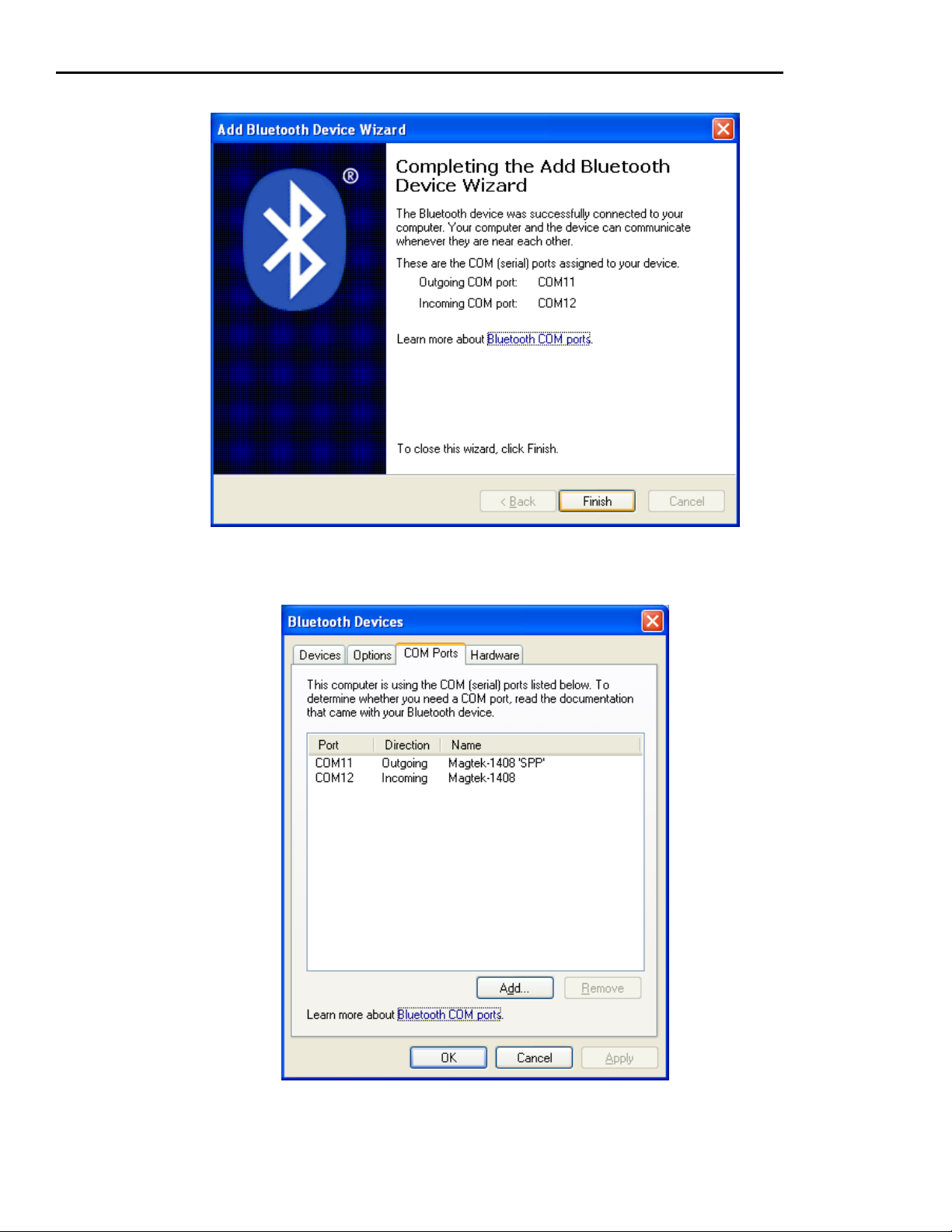
Bluetooth MagneSafe V5 Swipe Reader
After the device is installed, note the Outgoing COM port: for communication purposes.
Click Finish. The Bluetooth reader is now ready to use.
If you need to discover the COM port values later on, open the Bluetooth utility and select the COM Ports tab:
56
Page 65

APPENDIX C. INSTALLING BLUETOOTH WITH KENSINGTON DRIVER
Put the installation CD in your CD drive. Click Click! To Install to begin. (If the CD does not autoplay, select
Start>Run… and type: D:autorun.exe, where ‘D’ is the letter of your CD drive.)
Click Next
57
Page 66

Bluetooth MagneSafe V5 Swipe Reader
Select I accept the terms in the license agreement, and click Next
Click Next to continue.
58
Page 67

Appendix C. Installing Bluetooth with Kens ington Driver
Click Install to begin installing the software. A status window shows the progress of the installation.
59
Page 68

Bluetooth MagneSafe V5 Swipe Reader
Click OK to continue.
Click Finish and then click Quit on the main CD contents screen.
60
Page 69
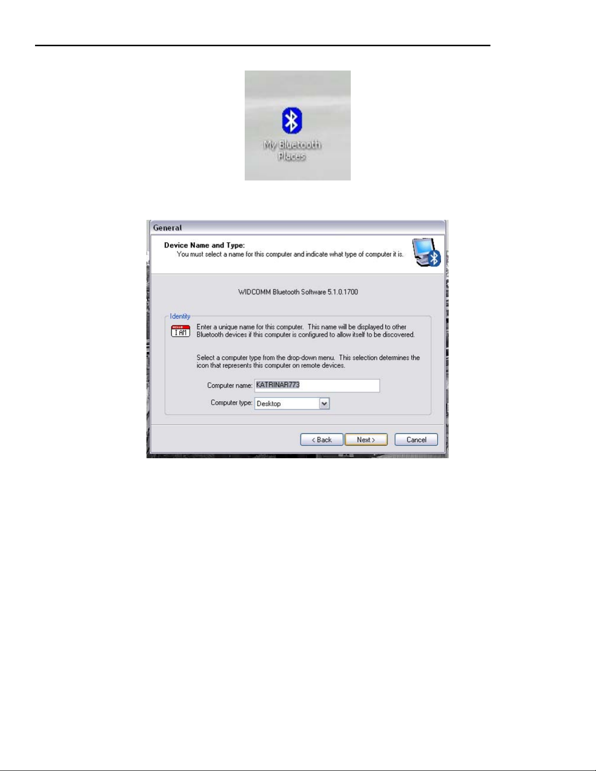
Appendix C. Installing Bluetooth with Kens ington Driver
Double-click My Bluetooth Places on the desktop to begin the setup.
Click Next to continue.
61
Page 70
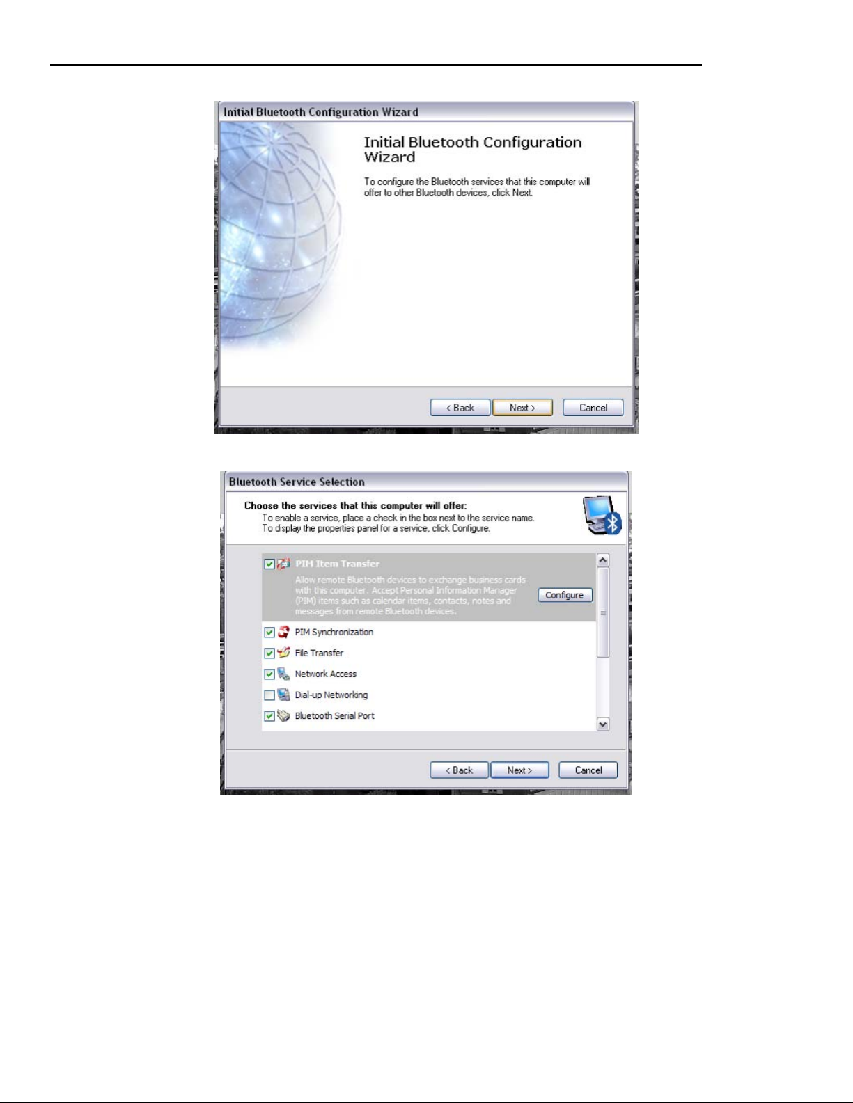
Bluetooth MagneSafe V5 Swipe Reader
Click Next to continue.
Click Next to continue.
62
Page 71

Appendix C. Installing Bluetooth with Kens ington Driver
If you have another Bluetooth device, Click Next. Otherwise, click Skip.
When you are finished configuring the Bluetooth USB Adapter and any other Bluetooth devices, click Finish.
63
Page 72
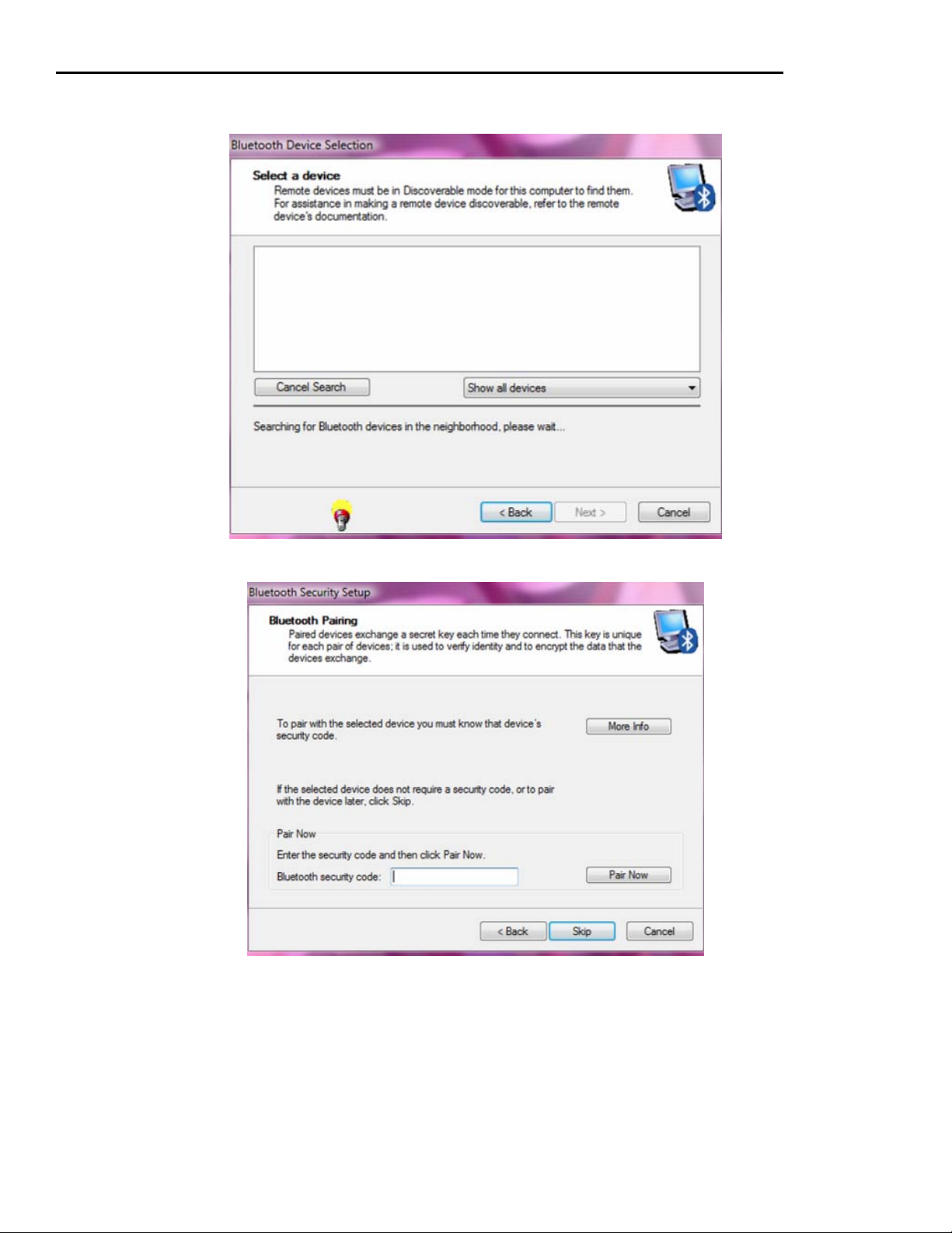
Bluetooth MagneSafe V5 Swipe Reader
To add a device make sure the device is on while the program is searching. Once the device has been found,
select the device and click Next.
Enter the security code, which is set to 1234 for initial use, and click Pair Now
64
Page 73

Appendix C. Installing Bluetooth with Kens ington Driver
Check the box next to SPP, then click Next.
Click Finish to complete the process.
65
Page 74

Bluetooth MagneSafe V5 Swipe Reader
66
Page 75

APPENDIX D. COMMAND EXAMPLES
This Appendix gives examples of command sequences and cryptographic operations. The intent is to clarify
any ambiguities the user might find in the body of the document. Each example shows a sequence as it actually
runs, thus the user can check algorithms against the examples to assure they are computing correctly.
Example 1: Changing from Security Level 3 to Security Level 4:
; This script demonstrates changing from Security Level 3 to Security Level 4.
; It assumes the reader is at Security Level 3 with the ANSI X9.24 Example
; key loaded and the KSN counter set to 2.
09 00 ; Get current KSN (should be FFFF9876543210E00002)
Request : CMND=09, LEN=00, DATA=
Response : RC= 00, LEN=0A, DATA=FF FF 98 76 54 32 10 E0 00 02
; For KSN 2, MAC Key: C46551CEF9FDDBB0 AA9AD834130DC4C7
;
; The command to change Security Level looks like: 15 05 04 nnnnnnnn
; where nnnnnnnn is the MAC.
;
; The data to be MACd is: 15 05 04
; Data to be MACd must be in blocks of eight bytes, so we left justify and
; zero fill the block to get: 15 05 04 00 00 00 00 00 (This is the block to MAC)
; For convenience show it as the compacted form: 1505040000000000
;
; The MAC algorithm run with this data uses the following cryptographic
; operations:
;
; Single DES Encrypt the data to be MACd with the left half of the MAC Key:
; 1505040000000000 1DES Enc with C46551CEF9FDDBB0 = 735323A914B9482E
;
; Single DES Decrypt the result with the right half of the MAC Key:
; 735323A914B9482E 1DES Dec with AA9AD834130DC4C7 = 390E2E2AC8CB4EE6
;
; Single DES Encrypt the result with the left half of the MAC Key:
; 390E2E2AC8CB4EE6 1DES Enc with C46551CEF9FDDBB0 = D9B7F3D8064C4B26
;
; The leftmost four bytes of the final result are the MAC = D9B7F3D8
;
; Send the MACd Set Security Level command
15 05 04 D9B7F3D8
Request : CMND=15, LEN=05, DATA=04 D9 B7 F3 D8
Response : RC= 00, LEN=00, DATA=
02 00 ; Reset so changes take effect
Request : CMND=02, LEN=00, DATA=
Response : RC= 00, LEN=00, DATA=
Delay : (waited 5 seconds)
09 00 ; Get current KSN (should be FFFF9876543210E00003)
Request : CMND=09, LEN=00, DATA=
Response : RC= 00, LEN=0A, DATA=FF FF 98 76 54 32 10 E0 00 03
15 00 ; Get current Security Level (Should be 04)
Request : CMND=15, LEN=00, DATA=
Response : RC= 00, LEN=01, DATA=04
67
Page 76

Bluetooth MagneSafe V5 Swipe Reader
Example 2: Configuring a reader after encryption is enabled (Security Level 3 or 4).
; This script demonstrates configuration commands.
; It assumes the reader is at Security Level 3 or 4 and that the KSN counter
; is at 0x10.
09 00 ; Get current KSN (should be FFFF9876543210E00010)
Request : CMND=09, LEN=00, DATA=
Response : RC= 00, LEN=0A, DATA=FF FF 98 76 54 32 10 E0 00 10
; For this KSN counter the MAC Key is: 59598DCBD9BD6BC0 94165CE45358A057
00 01 02 ; Get current Polling Interval
Request : CMND=00, LEN=01, DATA=02
Response : RC= 00, LEN=01, DATA=01
00 01 1E ; Get current Pre Card String
Request : CMND=00, LEN=01, DATA=1E
Response : RC= 00, LEN=00, DATA=
; Form MAC for Set Property command
; Message to be sent is: 01 05 1E nnnnnnnn (nnnnnnnn is the MAC)
; Message to be MACd is: 01051E0000000000
; This is the simplest MAC, simply TDES encrypt the message to be MACd with
; the MAC Key:
; 01051E0000000000 MACd with 59598DCBD9BD6BC0 94165CE45358A057
; gets 5157FCBC179B0B95
; MAC is first four bytes: 5157FCBC
01 05 1E 5157FCBC ; Set to ""
Request : CMND=01, LEN=05, DATA=1E 51 57 FC BC
Response : RC= 00, LEN=00, DATA=
00 01 1F ; Get current Post Card String
Request : CMND=00, LEN=01, DATA=1F
Response : RC= 00, LEN=00, DATA=
; Form MAC for Set Property command
; Message to be sent is: 01 05 1F nnnnnnnn (nnnnnnnn is the MAC)
; Message to be MACd is: 01051F0000000000
; This is the simplest MAC, simply TDES encrypt the message to be MACd with
; the MAC Key:
; 01051F0000000000 MACd with 2B5F01F4F0CCFAEA 639D523231BFE4A2
; gets 4885838CCC672376
; MAC is first four bytes: 4885838C 01 05 1F 4885838C ; Set to ""
Request : CMND=01, LEN=05, DATA=1F 48 85 83 8C Response : RC= 00, LEN=00,
DATA=
00 01 20 ; Get current Pre Track String
Request : CMND=00, LEN=01, DATA=20
Response : RC= 00, LEN=00, DATA=
; Form MAC for Set Property command
; Message to be sent is: 01 05 20 nnnnnnnn (nnnnnnnn is the MAC)
; Message to be MACd is: 0105200000000000
; This is the simplest MAC, simply TDES encrypt the message to be MACd with
; the MAC Key:
; 0105200000000000 MACd with 9CF640F279C251E6 15F725EEEAC234AF
; gets 442A09E6588BBF04
; MAC is first four bytes: 442A09E6
68
Page 77

Appendix D. Command Examples
01 05 20 442A09E6 ; Set to ""
Request : CMND=01, LEN=05, DATA=20 44 2A 09 E6
Response : RC= 00, LEN=00, DATA=
00 01 21 ; Get current Post Track String
Request : CMND=00, LEN=01, DATA=21
Response : RC= 00, LEN=00, DATA=
; Form MAC for Set Property command
; Message to be sent is: 01 05 21 nnnnnnnn (nnnnnnnn is the MAC)
; Message to be MACd is: 0105210000000000
; This is the simplest MAC, simply TDES encrypt the message to be MACd with
; the MAC Key:
; 0105210000000000 MACd with C3DF489FDF11ACB4 F03DE97C27DCB32F
; gets 1FA9A44C703099E1
; MAC is first four bytes: 1FA9A44C
01 05 21 1FA9A44C ; Set to ""
Request : CMND=01, LEN=05, DATA=21 1F A9 A4 4C
Response : RC= 00, LEN=00, DATA=
00 01 22 ; Get current Termination String
Request : CMND=00, LEN=01, DATA=22
Response : RC= 00, LEN=01, DATA=0D
; Form MAC for Set Property command
; Message to be sent is: 01 06 22 0D nnnnnnnn (nnnnnnnn is the MAC)
; Message to be MACd is: 0106220D00000000
; This is the simplest MAC, simply TDES encrypt the message to be MACd with
; the MAC Key:
; 0106220D00000000 MACd with 6584885077214CF1 4737FA93F92334D2
; gets 381AD461F2BDC522
; MAC is first four bytes: 381AD461
01 06 22 0D 381AD461 ; Set to "<ENTER>"
Request : CMND=01, LEN=06, DATA=22 0D 38 1A D4 61
Response : RC= 00, LEN=00, DATA=
00 01 2C ; Get current Format Code
Request : CMND=00, LEN=01, DATA=2C
Response : RC= 00, LEN=05, DATA=31 FF FF FF FF
; Form MAC for Set Property command
; Message to be sent is: 01 09 2C 31303030 nnnnnnnn (nnnnnnnn is the MAC)
; Message to be MACd is: 01092C3130303000
; This is the simplest MAC, simply TDES encrypt the message to be MACd with
; the MAC Key:
; 01092C3130303000 MACd with E161D1956A6109D2 F37AFD7F9CC3969A
; gets D153861529E88020
; MAC is first four bytes: D1538615
01 09 2C 31303030 D1538615 ; Set to "1000"
Request : CMND=01, LEN=09, DATA=2C 31 30 30 30 D1538615
Response : RC= 00, LEN=00, DATA=
02 00 ; Reset so changes take effect
Request : CMND=02, LEN=00, DATA=
Response : RC= 00, LEN=00, DATA=
Delay : (waited 5 seconds)
69
Page 78

Bluetooth MagneSafe V5 Swipe Reader
00 01 1E ; Get current Pre Card String (should return "")
Request : CMND=00, LEN=01, DATA=1E
Response : RC= 00, LEN=00, DATA=
00 01 1F ; Get current Post Card String (should return "")
Request : CMND=00, LEN=01, DATA=1F
Response : RC= 00, LEN=00, DATA=
00 01 20 ; Get current Pre Track String (should return "")
Request : CMND=00, LEN=01, DATA=20
Response : RC= 00, LEN=00, DATA=
00 01 21 ; Get current Post Track String (should return "")
Request : CMND=00, LEN=01, DATA=21
Response : RC= 00, LEN=00, DATA=
00 01 22 ; Get current Termination String (should return "<ENTER>")
Request : CMND=00, LEN=01, DATA=22
Response : RC= 00, LEN=01, DATA=0D
00 01 2C ; Get current Format Code
Request : CMND=00, LEN=01, DATA=2C
Response : RC= 00, LEN=04, DATA=31 30 30 30
Example 3: Authentication. A reader already in Security Level 3 or 4 is put into the Authenticated
Mode, allowed to stay in that mode for a time, then Deactivated.
; This example demonstrates the Authentication Sequence.
; It is not scripted; some of the data is deliberately randomized. This
; makes it impossible for a simple script to produce the correct results.
; As an example it shows all the steps in authentication and deactivation.
; It assumes the reader is at Security Level 4, with the DUKPT KSN
; counter set to 2.
09 00 ; Get current KSN (should be FFFF9876543210E00002)
; Send the Activate Authenticated Mode command (4 minutes)
10 02 00F0
Request : CMND=10, LEN=02, DATA=00 F0
Response : RC= 00, LEN=1A, DATA=FF FF 98 76 54 32 10 E0 00 03 AA AA AA AA AA AA AA
AA DD DD DD DD DD DD DD DD
|------- Current KSN -------| |---- Challenge 1 ---
-| |---- Challenge 2 ----|
Response : RC= 00, LEN=1A, DATA=FF FF 98 76 54 32 10 E0 00 03 BE 5C 98 35 17 7E 45
2A A7 2D 2D B2 36 BF 29 D2
; Challenge 1 Encrypted: BE5C9835177E452A
; Challenge 2 Encrypted: A72D2DB236BF29D2
; Note that the KSN now ends with a counter of 3!
; Decrypt Challenge 1 using variant of Current Encryption Key
; (Current Encryption Key XOR with F0F0F0F0F0F0F0F0F0F0F0F0F0F0F0F0)
;
; Current Key 0DF3D9422ACA561A 47676D07AD6BAD05
; XOR F0F0F0F0F0F0F0F0 F0F0F0F0F0F0F0F0
; = FD0329B2DA3AA6EA B7979DF75D9B5DF5
;
70
Page 79

Appendix D. Command Examples
; BE5C9835177E452A TDES Dec with FD0329B2DA3AA6EA B7979DF75D9B5DF5 =
7549AB6EB4840003
;
; Note that the final two bytes of the result = 0003, matching the KSN as
; transmitted in the clear. This provides Authentication to the host that
; the reader is what it claims to be (proves key knowledge).
;
; Decrypt Challenge 2 using Current Encryption Key variant as above
; A72D2DB236BF29D2 TDES Dec with FD0329B2DA3AA6EA B7979DF75D9B5DF5 =
34DB9230698281B4
;
; Build an Activation Challenge Reply command (cmd, len, cryptogram)
; 11 08 XXXXXXXXXXXXXXXX
;
; The clear text input for the cryptogram is composed of the first six bytes
; of the decrypted Challenge 1 followed by two bytes specifying how long to
; stay in the Authenticated Mode.
;
; CCCCCCCCCCCC TTTT
;
; Time examples:
; For 30 seconds use 002E
; For 99 seconds use 0063
; For 480 seconds use 01E0
; For 1200 seconds use 04B0
;
; These fields are concatenated to form an eight byte block, we will use 480
; seconds:
;
; CCCCCCCCCCCC01E0
;
; The block is encrypted using a variant of the Current Encryption Key
; (Current Encryption Key XOR with 3C3C3C3C3C3C3C3C3C3C3C3C3C3C3C3C)
;
; Current Key 0DF3D9422ACA561A 47676D07AD6BAD05
; XOR 3C3C3C3C3C3C3C3C 3C3C3C3C3C3C3C3C
; = 31CFE57E16F66A26 7B5B513B91579139
;
; 7549AB6EB48401E0 TDES Enc with 31CFE57E16F66A26 7B5B513B91579139 =
RRRRRRRRRRRRRRRR
;
; Send the Activation Challenge Reply Command
11 08 A30DDE3BFD629ACD
; Build a Deactivate Authenticated Mode command (cmd, len, cryptogram)
; 12 08 XXXXXXXXXXXXXXXX
;
; The clear text input for the cryptogram is composed of the first seven bytes
; of the decrypted Challenge 2 followed by one byte specifying whether to
; increment the DUKPT KSN or not (00 = no increment, 01 = increment).
;
; DDDDDDDDDDDDDD II
;
; These fields are concatenated to form an eight byte block, we will specify
; No Increment:
;
; DDDDDDDDDDDDDD00
;
71
Page 80

Bluetooth MagneSafe V5 Swipe Reader
; The block is encrypted using a variant of the Current Encryption Key
; (Current Encryption Key XOR with 3C3C3C3C3C3C3C3C3C3C3C3C3C3C3C3C)
;
; Current Key 0DF3D9422ACA561A 47676D07AD6BAD05
; XOR 3C3C3C3C3C3C3C3C 3C3C3C3C3C3C3C3C
; = 31CFE57E16F66A26 7B5B513B91579139
;
; 34DB923069828100 TDES Enc with 31CFE57E16F66A26 7B5B513B91579139 = CA CB BD 5F 58
D5 C9 50
;
; Send the Deactivate Authenticated Mode command
12 08 CACBBD5F58D5C950
Example 4: Swipe decryption, Bluetooth Reader in Security Level 3 or 4:
This example shows the data received in a Card Swipe for a reader at Security Level 3,
KSN Count = 8. It will go on to show the steps to decrypt ALL the data received.
Raw Card Swipe Data:
Byte Content
0 %B5452000000007189^HOGAN/PAUL ^08040000000000
50 000000000?;5452000000007189=080400000000000000?+51
100 63000050000445=000000000000?|0600|C25C1D1197D31CAA
150 87285D59A892047426D9182EC11353C051ADD6D0F072A6CB34
200 36560B3071FC1FD11D9F7E74886742D9BEE0CFD1EA1064C213
250 BB55278B2F12|724C5DB7D6F901C7F0FEAE7908801093B3DBF
300 E51CCF6D483E789D7D2C007D539499BAADCC8D16CA2|E31234
350 A91059A0FBFE627954EE21868AEE3979540B67FCC40F61CECA
400 54152D1E|A1050000|8628E664C59BBAA232BA90BFB3E6B41D
450 6F4B691E633C311CBE6EE7466B81196EC07B12648DCAC4FD7F
500 D0E212B479C60BAD8C74F82F327667||21685F158B5C6BE0|F
550 FFF9876543210E00008|B78F||0000
The Card Swipe Data is broken down like this:
[P30]
[P32] [Tk1 SS] [Tk1 Masked Data] [ES] [P33]
[P32] [Tk2 SS] [Tk2 Masked Data] [ES] [P33]
[P32] [Tk3 SS] [Tk3 Masked Data] [ES] [P33]
[P31]
[P35] [Reader Encryption Status]
[P35] [Tk1 Encrypted Data (including TK1 SS and ES)]
[P35] [Tk2 Encrypted Data (including TK2 SS and ES)]
[P35] [Tk3 Encrypted Data (including TK3 SS and ES)]
[P35] [MagnePrint Status]
[P35] [Encrypted MagnePrint data]
[P35] [Device serial number]
[P35] [Encrypted Session ID]
[P35] [DUKPT serial number/counter]
[P35] [Clear Text CRC]
[P35] [Encrypted CRC]
[P35] [Format Code]
[P34]
Each of the Pxx elements has the default value in this configuration, thus we can
reinterpret the format as:
72
Page 81

Appendix D. Command Examples
%[Tk1 Masked Data]?
;[Tk2 Masked Data]?
+[Tk3 Masked Data]?
|[Reader Encryption Status]
|[Tk1 Encrypted Data (including TK1 SS and ES)]
|[Tk2 Encrypted Data (including TK2 SS and ES)]
|[Tk3 Encrypted Data (including TK3 SS and ES)]
|[MagnePrint Status]
|[Encrypted MagnePrint data]
|[Device serial number]
|[Encrypted Session ID]
|[DUKPT serial number/counter]
|[Clear Text CRC]
|[Encrypted CRC]
|[Format Code]
<ENTER>
Using this information, we can put the respective data from the Raw Data into the
structure:
%B5452000000007189^HOGAN/PAUL ^08040000000000000000000?
;5452000000007189=080400000000000000?
+5163000050000445=000000000000?
|0600
|C25C1D1197D31CAA87285D59A892047426D9182EC11353C051ADD6D0F072A6CB3436560B3071FC1FD11D9F7
E74886742D9BEE0CFD1EA1064C213BB55278B2F12
|724C5DB7D6F901C7F0FEAE7908801093B3DBFE51CCF6D483E789D7D2C007D539499BAADCC8D16CA2
|E31234A91059A0FBFE627954EE21868AEE3979540B67FCC40F61CECA54152D1E
|A1050000
|8628E664C59BBAA232BA90BFB3E6B41D6F4B691E633C311CBE6EE7466B81196EC07B12648DCAC4FD7FD0E21
2B479C60BAD8C74F82F327667
|
|21685F158B5C6BE0
|FFFF9876543210E00008
|B78F
|
|0000
Note: The Device Serial Number field is empty because the DSN has not
been set.
Note: The Encrypted CRC field is empty because the default configuration
is to send it empty.
Note that at Security Level 3 the following fields are represented as
ASCII characters:
Masked Track data
Format Code
Note that all other fields are represented as Hexadecimal data, that is
two ASCII characters together give the value of a single byte.
The data is coherent structurally, let's work on decryption.
First, we note the KSN = FFFF9876543210E00008, counter is 8.
For the standard ANSI key example, counter 8 gets us the following
Encryption Key: 27F66D5244FF621E AA6F6120EDEB427F
73
Page 82

Bluetooth MagneSafe V5 Swipe Reader
There are five encrypted fields: Tracks 1, 2, and 3 encrypted data,
Encrypted MagnePrint data, Encrypted Session ID. We will show the decryption
of each of these fields in detail. For convenience each will be grouped as
blocks of eight bytes.
Track 1 encrypted data
Block # 1 C25C1D1197D31CAA
2 87285D59A8920474
3 26D9182EC11353C0
4 51ADD6D0F072A6CB
5 3436560B3071FC1F
6 D11D9F7E74886742
7 D9BEE0CFD1EA1064
8 C213BB55278B2F12
Appendix A tells us to decrypt the last block:
C213BB55278B2F12 TDES Dec with 27F66D5244FF621E AA6F6120EDEB427F
gets E98ED0F0D1EA1064
XOR D9BEE0CFD1EA1064
gets 3030303F00000000 (decrypted last block)
Continue on in reverse block order:
D9BEE0CFD1EA1064 TDES Dec with 27F66D5244FF621E AA6F6120EDEB427F
gets E12DA84C41B85772
XOR D11D9F7E74886742
gets 3030373235303030 (decrypted block 7)
Continue on in reverse block order:
D11D9F7E74886742 TDES Dec with 27F66D5244FF621E AA6F6120EDEB427F
gets 0704673B0041CC2F
XOR 3436560B3071FC1F
gets 3332313030303030 (decrypted block 6)
Continue on in reverse block order:
3436560B3071FC1F TDES Dec with 27F66D5244FF621E AA6F6120EDEB427F
gets 718DF68EC04A96FF
XOR 51ADD6D0F072A6CB
gets 2020205E30383034 (decrypted block 5)
Continue on in reverse block order:
51ADD6D0F072A6CB TDES Dec with 27F66D5244FF621E AA6F6120EDEB427F
gets 0989597B8D3373E0
XOR 26D9182EC11353C0
gets 2F5041554C202020 (decrypted block 4)
Continue on in reverse block order:
26D9182EC11353C0 TDES Dec with 27F66D5244FF621E AA6F6120EDEB427F
gets BF110311E7D5453A
XOR 87285D59A8920474
gets 38395E484F47414E (decrypted block 3)
Continue on in reverse block order:
87285D59A8920474 TDES Dec with 27F66D5244FF621E AA6F6120EDEB427F
gets F2692820A5E12B9B
XOR C25C1D1197D31CAA
gets 3035353132323731 (decrypted block 2)
74
Page 83

Appendix D. Command Examples
Continue on in reverse block order:
C25C1D1197D31CAA TDES Dec with 27F66D5244FF621E AA6F6120EDEB427F
gets 2542353435323330 (decrypted block 1)
Ordering the decrypted blocks 1st to last we get:
HEX ASCII
2542353435323330 %B545230
3035353132323731 05512271
38395E484F47414E 89^HOGAN
2F5041554C202020 /PAUL
2020205E30383034 ^0804
3332313030303030 32100000
3030373235303030 00725000
3030303F00000000 000?
We can ignore the last four bytes because they are all hex 00 and fall
after the End Sentinel.
ASCII string "%B5452300551227189^HOGAN/PAUL ^08043210000000725000000?"
This is an accurate decryption of the track.
Track 2 encrypted data
Block # 1 724C5DB7D6F901C7
2 F0FEAE7908801093
3 B3DBFE51CCF6D483
4 E789D7D2C007D539
5 499BAADCC8D16CA2
Appendix A tells us to decrypt the last block:
499BAADCC8D16CA2 TDES Dec with 27F66D5244FF621E AA6F6120EDEB427F
gets D0BBE2E2FF07D539
XOR E789D7D2C007D539
gets 373235303F000000 (decrypted last block)
Continue on in reverse block order:
E789D7D2C007D539 TDES Dec with 27F66D5244FF621E AA6F6120EDEB427F
gets 82EBCE61FCC6E4B3
XOR B3DBFE51CCF6D483
gets 3130303030303030 (decrypted block 4)
Continue on in reverse block order:
B3DBFE51CCF6D483 TDES Dec with 27F66D5244FF621E AA6F6120EDEB427F
gets C9C39E4138B423A1
XOR F0FEAE7908801093
gets 393D303830343332 (decrypted block 3)
Continue on in reverse block order:
F0FEAE7908801093 TDES Dec with 27F66D5244FF621E AA6F6120EDEB427F
gets 47796C85E4CE30FF
XOR 724C5DB7D6F901C7
gets 3535313232373138 (decrypted block 2)
Continue on in reverse block order:
724C5DB7D6F901C7 TDES Dec with 27F66D5244FF621E AA6F6120EDEB427F
gets 3B35343532333030 (decrypted block 1)
75
Page 84

Bluetooth MagneSafe V5 Swipe Reader
Ordering the decrypted blocks 1st to last we get:
HEX ASCII
3B35343532333030 ;5452300
3535313232373138 55122718
393D303830343332 9=080432
3130303030303030 10000000
373235303F000000 7250?
We can ignore the last three bytes because they are all hex 00 and fall
after the End Sentinel.
ASCII string ";5452300551227189=080432100000007250?"
This is an accurate decryption of the track.
Track 3 encrypted data
Block # 1 E31234A91059A0FB
2 FE627954EE21868A
3 EE3979540B67FCC4
4 0F61CECA54152D1E
Appendix A tells us to decrypt the last block:
0F61CECA54152D1E TDES Dec with 27F66D5244FF621E AA6F6120EDEB427F
gets DE0949643B57C3C4
XOR EE3979540B67FCC4
gets 3030303030303F00 (decrypted last block)
Continue on in reverse block order:
EE3979540B67FCC4 TDES Dec with 27F66D5244FF621E AA6F6120EDEB427F
gets CB5F4964DE11B6BA
XOR FE627954EE21868A
gets 353D303030303030 (decrypted block 3)
Continue on in reverse block order:
FE627954EE21868A TDES Dec with 27F66D5244FF621E AA6F6120EDEB427F
gets D32A0499226994CF
XOR E31234A91059A0FB
gets 3038303032303434 (decrypted block 2)
Continue on in reverse block order:
E31234A91059A0FB TDES Dec with 27F66D5244FF621E AA6F6120EDEB427F
gets 2B35313633343939 (decrypted block 1)
Ordering the decrypted blocks 1st to last we get:
HEX ASCII
2B35313633343939 +5163499
3038303032303434 08002044
353D303030303030 3=000000
3030303030303F00 000000?
We can ignore the last byte because it is hex 00 and falls after the
End Sentinel.
ASCII string "+5163499080020443=000000000000? "
This is an accurate decryption of the track.
76
Page 85

Appendix D. Command Examples
MagnePrint data
Block # 1 8628E664C59BBAA2
2 32BA90BFB3E6B41D
3 6F4B691E633C311C
4 BE6EE7466B81196E
5 C07B12648DCAC4FD
6 7FD0E212B479C60B
7 AD8C74F82F327667
Appendix A tells us to decrypt the last block:
AD8C74F82F327667 TDES Dec with 27F66D5244FF621E AA6F6120EDEB427F
gets 09162DCA11E5C60B
XOR 7FD0E212B479C60B
gets 76C6CFD8A59C0000 (decrypted last block)
Continue on in reverse block order:
7FD0E212B479C60B TDES Dec with 27F66D5244FF621E AA6F6120EDEB427F
gets AE81BFA4A2C80006
XOR C07B12648DCAC4FD
gets 6EFAADC02F02C4FB (decrypted block 6)
Continue on in reverse block order:
C07B12648DCAC4FD TDES Dec with 27F66D5244FF621E AA6F6120EDEB427F
gets AAC8D06ACCF27E6D
XOR BE6EE7466B81196E
gets 14A6372CA7736703 (decrypted block 5)
Continue on in reverse block order:
BE6EE7466B81196E TDES Dec with 27F66D5244FF621E AA6F6120EDEB427F
gets 01D78CB7D1DAEA95
XOR 6F4B691E633C311C
gets 6E9CE5A9B2E6DB89 (decrypted block 4)
Continue on in reverse block order:
6F4B691E633C311C TDES Dec with 27F66D5244FF621E AA6F6120EDEB427F
gets 0D2620B051231748
XOR 32BA90BFB3E6B41D
gets 3F9CB00FE2C5A355 (decrypted block 3)
Continue on in reverse block order:
32BA90BFB3E6B41D TDES Dec with 27F66D5244FF621E AA6F6120EDEB427F
gets 41499B60A6AAD427
XOR 8628E664C59BBAA2
gets C7617D0463316E85 (decrypted block 2)
Continue on in reverse block order:
8628E664C59BBAA2 TDES Dec with 27F66D5244FF621E AA6F6120EDEB427F
gets 010002D4B69CD2C0 (decrypted block 1)
***********************
Ordering the decrypted blocks 1st to last we get:
HEX
010002D4B69CD2C0
C7617D0463316E85
3F9CB00FE2C5A355
6E9CE5A9B2E6DB89
14A6372CA7736703
6EFAADC02F02C4FB
76C6CFD8A59C0000
77
Page 86

Bluetooth MagneSafe V5 Swipe Reader
We can ignore the last two bytes because we know the MagnePrint data is
actually 54 bytes long.
010002D4B69CD2C0C7617D0463316E853F9CB00FE2C5A3556E9CE5A9B2E6DB8914A6372C
A77367036EFAADC02F02C4FB76C6CFD8A59C0000
This is an accurate decryption of the MagnePrint data.
Encrypted Session ID (user didn't load, all zeroes)
21685F158B5C6BE0
As this is a simple eight byte block, we only need decrypt it with
the appropriate key:
21685F158B5C6BE0 TDES Dec with 27F66D5244FF621E AA6F6120EDEB427F
gets 0000000000000000
This is an accurate decryption of the Encrypted Session ID, which
was not loaded by the user and thus was all zeroes.
78
Page 87

APPENDIX E. IDENTIFYING ISO/ABA AND AAMVA CARDS
ISO/ABA FI NANC IAL CARD S
1. If low level decoding algorithm finds data for available tracks to be in the ISO format
particular to each track, the card is classified as ISO. In order to be considered for ISO
Financial masking, the card must first be classed as ISO.
2. In order for any track on a card to be considered for ISO/ABA masking, the card must be
classified as ISO by the low level decoding algorithm.
3. ISO/ABA masking is considered for each track independently. One track may qualify for
masking and another not.
4. Track 1
a. The goal is to send the Format Code in the clear, the PAN partially masked, the
Name and Expiration Date in the clear, and the rest of the track masked.
b. If Format Code, PAN, Name, or Expiration Date are not correctly structured, the
rest of the track (from the point of discrepancy) will be sent in the clear.
c. If the Format Code, PAN, Name, or Expiration Date contain the ‘?’ character
(End Sentinel), the field is not correctly structured.
d. A correctly structured Format Code is the first character on the card and contains
the character ‘B’.
e. A correctly structured PAN has a maximum of 19 digits and is ended by the
character ‘^’ (Field Separator).
f. A correctly structured Name has a maximum of 26 characters and is ended by the
character ‘^’ (Field Separator).
g. A correctly structured Expiration Date has 4 characters.
5. Tracks 2 & 3
a. The goal is to send the PAN partially masked, the Expiration Date in the clear,
and the rest of the track masked.
b. If the PAN or Expiration Date are not correctly structured, the rest of the track
(from the point of discrepancy) will be sent in the clear.
c. If the PAN or Expiration Date contain the ‘?’ character (End Sentinel), the field is
not correctly structured.
d. A correctly structured PAN has a maximum of 19 digits and is ended by the
character ‘=’ (Field Sepa rat or).
e. A correctly structured Expiration Date has 4 characters.
AAMVA DRIVER LICENSES
1. If the card reader reads three tracks of data and Track 1 is formatted per ISO Track 1
rules, Track 2 is formatted per ISO Track 2 rules, and Track 3 is formatted per ISO Track
1 rules, the card is considered to be an AAMVA card. Some MagTek readers do not
support reading of Track 3, so this rule will not apply on such readers.
2. If low level decoding algorithm finds data for available tracks to be in the ISO format
particular to each track, and Track 2 contains a correctly structured PAN field whose first
6 digits are “604425” or contain values in the range “636000” to “636062” inclusive, the
card is considered to be an AAMVA card.
79
Page 88

Bluetooth MagneSafe V5 Swipe Reader
3. AAMVA card masking, when enabled, works as follows:
a. Tracks 1 & 3 are sent entirely masked i.e., zeros are supplied in all character
positions.
b. Track 2:
• The goal is to send the Driver License ID (DLID) partially masked, the
Expiration Date in the clear, the Birth Date in the clear, and the rest of the
track masked.
• If the DLID, Expiration Date, or Birth Date are not correctly structured, the
rest of the track (from the point of discrepancy) will be sent in the clear.
• If the DLID, Expiration Date, or Birth Date contain the ‘?’ character (End
Sentinel), the field is not correctly structured.
• A correctly structured DLID has a maximum of 19 digits and is ended by the
character ‘=’ (Field Sepa rat or).
• A correctly structured Expiration Date has 4 characters.
• A correctly structured Birth Date has 8 characters.
80
 Loading...