

Page 1
DynaPro Mini
PIN Encryption Device
Programmer’s Reference (Commands)
July 25, 2014
Manual Part Number:
99875629-2.01
REGISTERED TO ISO 9001:2008
MagTek I 1710 Apollo Court I Seal Beach, CA 90740 I Phone: (562) 546-6400 I Technical Support: (888) 624-8350
www.magtek.com
Page 2

Copyright © 2006 - 2014 MagTek, Inc.
Rev Number
Date
Notes
1.01
Feb 18, 2014
Initial Release based on 99200078 7.01
2.01
July 25, 2014
Update based on 99200078-8.01: Update usage tables for
0x1A, 0xA1, 0xA2; apply consistent captions to tables and
figures; add kernel IDs; clarify HID Usages; add 0x1F, 0x2E
usages in report descriptor and elsewhere; add BLE properties;
misc. clarifications and accuracy fixes; add Report 0x06
bitmap option, Report 0x1F, Report 0x2E
Printed in the United States of America
Information in this publication is subject to change without notice and may contain technical inaccuracies
or graphical discrepancies. Changes or improvements made to this product will be updated in the next
publication release. No part of this document may be reproduced or transmitted in any form or by any
means, electronic or mechanical, for any purpose, without the express written permission of MagTek, Inc.
MagTek® is a registered trademark of MagTek, Inc.
MagnePrint® is a registered trademark of MagTek, Inc.
Magensa™ is a trademark of MagTek, Inc.
MagneSafe™ is a trademark of MagTek, Inc.
DynaPro™ and DynaPro Mini™ are trademarks of MagTek, Inc.
Bluetooth® is a registered trademark of Bluetooth SIG.
iPhone®, iPod®, iPad®, and Mac® are registered trademarks of Apple Inc., registered in the U.S. and
other countries. App StoreSM is a service mark of Apple Inc., registered in the U.S. and other countries.
IOS is a trademark or registered trademark of Cisco in the U.S. and other countries and is used by Apple
Inc. under license.
Microsoft® and Windows® are registered trademarks of Microsoft Corporation.
All other system names and product names are the property of their respective owners.
Table 0.1 - Revisions
DynaPro Mini| PIN Encryption Device | Programmer’s Reference (Commands)
Page 2
Page 3

LIMITED WARRANTY
MagTek warrants that the products sold pursuant to this Agreement will perform in accordance with
MagTek’s published specifications. This warranty shall be provided only for a period of one year from
the date of the shipment of the product from MagTek (the “Warranty Period”). This warranty shall apply
only to the “Buyer” (the original purchaser, unless that entity resells the product as authorized by
MagTek, in which event this warranty shall apply only to the first repurchaser).
During the Warranty Period, should this product fail to conform to MagTek’s specifications, MagTek
will, at its option, repair or replace this product at no additional charge except as set forth below. Repair
parts and replacement products will be furnished on an exchange basis and will be either reconditioned or
new. All replaced parts and products become the property of MagTek. This limited warranty does not
include service to repair damage to the product resulting from accident, disaster, unreasonable use,
misuse, abuse, negligence, or modification of the product not authorized by MagTek. MagTek reserves
the right to examine the alleged defective goods to determine whether the warranty is applicable.
Without limiting the generality of the foregoing, MagTek specifically disclaims any liability or warranty
for goods resold in other than MagTek’s original packages, and for goods modified, altered, or treated
without authorization by MagTek.
Service may be obtained by delivering the product during the warranty period to MagTek (1710 Apollo
Court, Seal Beach, CA 90740). If this product is delivered by mail or by an equivalent shipping carrier,
the customer agrees to insure the product or assume the risk of loss or damage in transit, to prepay
shipping charges to the warranty service location, and to use the original shipping container or equivalent.
MagTek will return the product, prepaid, via a three (3) day shipping service. A Return Material
Authorization (“RMA”) number must accompany all returns. Buyers may obtain an RMA number by
contacting MagTek Support Services at (888) 624-8350.
Each buyer understands that this MagTek product is offered as is. MagTek makes no other warranty,
express or implied, and MagTek disclaims any warranty of any other kind, including any warranty of
merchantability or fitness for a particular purpose.
If this product does not conform to MagTek’s specifications, the sole remedy shall be repair or
replacement as provided above. MagTek’s liability, if any, shall in no event exceed the total amount paid
to MagTek under this agreement. In no event will MagTek be liable to the buyer for any damages,
including any lost profits, lost savings, or other incidental or consequential damages arising out of the use
of, or inability to use, such product, even if MagTek has been advised of the possibility of such damages,
or for any claim by any other party.
LIMITATION ON LIABILITY
Except as provided in the sections relating to MagTek’s Limited Warranty, MagTek’s liability under this
agreement is limited to the contract price of this product.
MagTek makes no other warranties with respect to the product, expressed or implied, except as may be
stated in this agreement, and MagTek disclaims any implied warranty, including without limitation any
implied warranty of merchantability or fitness for a particular purpose.
MagTek shall not be liable for contingent, incidental, or consequential damages to persons or property.
MagTek further limits its liability of any kind with respect to the product, including any negligence on its
part, to the contract price for the goods.
DynaPro Mini| PIN Encryption Device | Programmer’s Reference (Commands)
Page 3
Page 4

MagTek’s sole liability and buyer’s exclusive remedies are stated in this section and in the section
relating to MagTek’s Limited Warranty.
FCC WARNING STATEMENT
This equipment has been tested and was found to comply with the limits for a Class B digital device
pursuant to Part 15 of FCC Rules. These limits are designed to provide reasonable protection against
harmful interference when the equipment is operated in a residential environment. This equipment
generates, uses, and can radiate radio frequency energy and, if not installed and used in accordance with
the instruction manual, may cause harmful interference with radio communications. However, there is no
guarantee that interference will not occur in a particular installation.
FCC COMPLIANCE STATEMENT
This device complies with Part 15 of the FCC Rules. Operation of this device is subject to the following
two conditions: (1) this device may not cause harmful interference, and (2) this device must accept any
interference received, including interference that may cause undesired operation.
CANADIAN DOC STATEMENT
This digital apparatus does not exceed the Class B limits for radio noise from digital apparatus set out in
the Radio Interference Regulations of the Canadian Department of Communications.
Le présent appareil numérique n’émet pas de bruits radioélectriques dépassant les limites applicables aux
appareils numériques de la classe B prescrites dans le Réglement sur le brouillage radioélectrique édicté
par le ministère des Communications du Canada.
This Class B digital apparatus complies with Canadian ICES-003.
Cet appareil numérique de la classe B est conformé à la norme NMB-003 du Canada.
CE STANDARDS
Testing for compliance with CE requirements was performed by an independent laboratory. The unit
under test was found compliant with standards established for Class B devices.
UL/CSA
This product is recognized per Underwriter Laboratories and Canadian Underwriter Laboratories 1950.
ROHS STATEMENT
When ordered as RoHS compliant, this product meets the Electrical and Electronic Equipment (EEE)
Reduction of Hazardous Substances (RoHS) European Directive 2002/95/EC. The marking is clearly
recognizable, either as written words like “Pb-free,” “lead-free,” or as another clear symbol ( ).
DynaPro Mini| PIN Encryption Device | Programmer’s Reference (Commands)
Page 4
Page 5

0 - Table of Contents
Table of Contents
LIMITED WARRANTY .......................................................................................................................... 3
FCC WARNING STATEMENT .............................................................................................................. 4
FCC COMPLIANCE STATEMENT ........................................................................................................ 4
CANADIAN DOC STATEMENT ............................................................................................................ 4
CE STANDARDS .................................................................................................................................. 4
UL/CSA ................................................................................................................................................. 4
RoHS STATEMENT .............................................................................................................................. 4
Table of Contents ............................................................................................................................... 5
1 Introduction ............................................................................................................................... 10
1.1 About This Document ....................................................................................................... 10
1.2 Nomenclature .................................................................................................................... 10
1.3 About Connection Types .................................................................................................. 10
1.4 About Device Features ..................................................................................................... 10
1.5 About APIs .......................................................................................................................... 11
2 Connection Types ...................................................................................................................... 11
2.1 How to Use USB Connections .......................................................................................... 11
2.1.1 About HID Usages ...................................................................................................... 12
2.1.1.1 About Reports .................................................................................................... 12
2.1.1.2 About the Report Descriptor ............................................................................ 12
2.2 How to Use Apple iOS UART Connections ..................................................................... 20
2.3 How to Use BLE Connections .......................................................................................... 21
3 Command Set ........................................................................................................................... 24
3.1 About Big Block Data Mode ............................................................................................ 24
3.2 About SRED / Non-SRED Firmware ............................................................................... 24
3.3 About Commands Tagged As “MAC” ............................................................................. 25
3.3.1 CA Public Key Data and Terminal and Payment Brand Data (TLV format) ...... 25
3.3.2 ARQC Requests (Smart Cards) ................................................................................ 25
3.3.2.1 Non-SRED ARQC request .................................................................................. 25
3.3.2.2 SRED ARQC Request ......................................................................................... 26
3.3.2.3 ARQC Response (Report 0xA4 – Acquirer Response) ................................. 27
3.3.3 Batch Data .................................................................................................................. 27
3.3.3.1 Non-SRED Batch Data ....................................................................................... 27
3.3.3.2 SRED Batch Data ............................................................................................... 28
DynaPro Mini| PIN Encryption Device | Programmer’s Reference (Commands)
Page 5
Page 6

0 - Table of Contents
3.4 General Feature Reports .................................................................................................. 29
3.4.1 Report 0x01 – Response ACK ................................................................................. 29
3.4.2 Report 0x02 – End Session ..................................................................................... 29
3.4.3 Report 0x03 – Request Swipe Card ....................................................................... 30
3.4.4 Report 0x04 – Request PIN Entry ........................................................................... 31
3.4.5 Report 0x05 – Cancel Command ........................................................................... 33
3.4.6 Report 0x06 – Request User Selection.................................................................. 33
3.4.7 Report 0x07 – Display Message ............................................................................. 34
3.4.8 Report 0x08 – Request Device Status ................................................................... 35
3.4.9 Report 0x09 – Set Device Configuration ............................................................... 35
3.4.10 Report 0x09 – Get Device Configuration ........................................................... 37
3.4.11 Report 0x0A – Request MSR Data ..................................................................... 38
3.4.12 Report 0x0B – Get Challenge .............................................................................. 38
3.4.13 Report 0x0D – Send Session Data - Amount .................................................... 39
3.4.14 Report 0x0D – Send Session Data - PAN .......................................................... 40
3.4.15 Report 0x0E – Get Information ........................................................................... 40
3.4.16 Report 0x0F – Login/Authenticate ..................................................................... 43
3.4.17 Report 0x0F – Logout ........................................................................................... 43
3.4.18 Report 0x10 – Send Big Block Data to Device ................................................. 43
3.4.19 Report 0x11 – Request Manual Card Entry ...................................................... 45
3.4.20 Report 0x14 – Request User Data Entry............................................................ 46
3.4.21 Report 0x1A – Request Device Information ..................................................... 47
3.4.22 Report 0x1C – Set/Get BLE Power Configuration (BLE Only) ......................... 50
3.4.23 Report 0x1D – Set BLE Module Control Data (BLE Only) ................................ 50
3.4.24 Report 0x1E – Set iAP Protocol Info (30-pin Only) ........................................... 51
3.4.25 Report 0x1E – Get iAP Protocol Info (30-pin Only) .......................................... 51
3.4.26 Report 0x1F – Request Clear Text User Data Entry ......................................... 51
3.4.27 Report 0x30 – Set / Get KSN .............................................................................. 52
3.4.28 Report 0x31 – Set KSN Encrypted Data ............................................................ 53
3.4.29 Report 0x32 – Set BIN Table Data (MAC) .......................................................... 54
3.4.30 Report 0x32 – Get BIN Table Data ..................................................................... 54
3.4.31 Report 0xFF – Device Reset ................................................................................ 55
3.5 General Input Reports ...................................................................................................... 55
3.5.1 Report 0x20 – Device State Report ....................................................................... 55
3.5.2 Report 0x21 – User Data Entry Response Report................................................ 56
DynaPro Mini| PIN Encryption Device | Programmer’s Reference (Commands)
Page 6
Page 7

0 - Table of Contents
3.5.3 Report 0x22 – Card Status Report ......................................................................... 56
3.5.4 Report 0x23 – Card Data Report ............................................................................ 57
3.5.5 Report 0x24 – PIN Response Report ..................................................................... 58
3.5.6 Report 0x25 – User Selection Response Report .................................................. 59
3.5.7 Report 0x27 – Display Message Done Report ..................................................... 59
3.5.8 Report 0x29 – Send Big Block Data to Host ......................................................... 59
3.5.8.1 Big Block Data for Authorization Request (ARQC) ....................................... 60
3.5.9 Report 0x2A – Delayed Response ACK ................................................................. 61
3.5.10 Report 0x2B – Test Response ............................................................................. 61
3.5.11 Report 0x2D –BLE Module Control Data (BLE Only) ........................................ 61
3.5.12 Report 0x2E – Clear Text User Data Entry Response Report ......................... 62
3.6 EMV-Related Reports........................................................................................................ 63
3.6.1 Report 0x2C – EMV Cardholder Interaction Status Report ................................ 63
3.6.2 Report 0xA1 – Set or Get EMV Tag(s) (MAC) ......................................................... 64
3.6.2.1 Setting EMV Tags ............................................................................................... 64
3.6.2.2 Getting EMV Tags ............................................................................................... 64
3.6.3 Report 0xA2 – Request Start EMV Transaction.................................................... 65
3.6.3.1 0xA2 Command Completion............................................................................ 67
3.6.4 Report 0xA4 – Acquirer Response (MAC).............................................................. 67
3.6.5 Report 0xA5 – Set or Get CA Public Key (MAC) .................................................... 68
3.6.6 Report 0xA8 – Get Kernel Info ................................................................................ 69
3.6.7 Report 0xAB – Request EMV Transaction Data (MAC) ........................................ 70
3.6.8 Report 0xAC – Merchant Bypass PIN Command ................................................. 76
Appendix A Examples ................................................................................................................ 77
A.1 How to Get MSR/PIN Data from the Device for a Bank Simulation ......................... 77
Appendix B Terminology ............................................................................................................ 80
Appendix C Status and Message Table ................................................................................... 83
Appendix D MagTek Custom EMV Tags ................................................................................... 87
Appendix E Configurations ........................................................................................................ 92
E.1 PIN-PAD Terminal Configuration .................................................................................... 92
E.2 Terminal Type .................................................................................................................... 92
E.3 Terminal Capabilities........................................................................................................ 92
E.4 Additional Terminal Capabilities .................................................................................... 93
Appendix F Error Codes ............................................................................................................. 96
F.1 H Codes ............................................................................................................................... 96
DynaPro Mini| PIN Encryption Device | Programmer’s Reference (Commands)
Page 7
Page 8

0 - Table of Contents
F.2 S Codes ............................................................................................................................... 96
F.3 C Codes ............................................................................................................................... 97
F.4 Device Offline K Codes ..................................................................................................... 98
F.5 Device offline A Codes ..................................................................................................... 98
Appendix G User-Defined Messages ........................................................................................ 99
Appendix H Factory Defaults ...................................................................................................101
H.1 Terminal Factory Defaults .............................................................................................101
H.2 Payment Brand Factory Defaults .................................................................................102
H.3 Certificate Authority Public Keys ..................................................................................103
Appendix I Language and Country Codes ...............................................................................104
I.1 Terminal Country Codes .................................................................................................104
I.2 Terminal Language Codes .............................................................................................104
Appendix J BLE Module Control Data ...................................................................................105
J.1 BLE Module Configuration Properties ..........................................................................105
J.1.1 Get property command ..........................................................................................105
J.1.2 Set property command ...........................................................................................105
J.1.3 Software ID property ...............................................................................................105
J.1.4 Bluetooth Device Address property ......................................................................106
J.1.5 Bluetooth Device Name property ..........................................................................106
J.1.6 Configuration Revision property............................................................................107
J.1.7 Power Timeout property .........................................................................................107
J.1.8 Power Control property ...........................................................................................108
J.1.9 Advertising Control property ..................................................................................109
J.1.10 Passkey property .....................................................................................................109
J.1.11 Desired Minimum Connection Interval Property ................................................110
J.1.12 Desired Maximum Connection Interval Property ...............................................110
J.1.13 Desired Slave Latency Property ............................................................................111
J.1.14 Desired Supervision Timeout Property ................................................................111
J.1.15 Connection Parameter Update Request Control Property ................................112
J.2 Other Commands ............................................................................................................112
J.2.1 Echo Command .......................................................................................................112
J.2.2 Reset Command ......................................................................................................113
J.2.3 Erase All Non-volatile Memory Command ...........................................................113
J.2.4 Erase All Bonds Command ....................................................................................113
DynaPro Mini| PIN Encryption Device | Programmer’s Reference (Commands)
Page 8
Page 9

0 - Table of Contents
DynaPro Mini| PIN Encryption Device | Programmer’s Reference (Commands)
Page 9
Page 10

1 - Introduction
Feature
IPAD
Legacy
DynaPro
DynaPro Plus
DynaPro Plus L1
DynaPro
Mini
30-pin
DynaPro Mini
BLE
General Features
Signature Capture (“SC”)
Yes
Yes
No
No
1 Introduction
1.1 About This Document
This document describes the master command set available through byte-by-byte direct communication
with DynaPro Mini PIN encryption devices (referred to in this document as “the device”).
1.2 Nomenclature
The general terms “device” and “host” are used in different, often incompatible ways in a multitude of
specifications and contexts. For example “host” may have different meanings in the context of USB
communication than it does in the context of networked financial transaction processing. In this
document, “device” and “host” are used strictly as follows:
Device refers to the Pin Encryption Device (PED) that receives and responds to the command set
specified in this document.
Host refers to the piece of general-purpose electronic equipment the device is connected or paired to,
which can send data to and receive data from the device. Host types include PC and Mac
computers/laptops, tablets, smartphones, teletype terminals, and even test harnesses. In many cases
the host may have custom software installed on it that communicates with the PED. When “host”
must be used differently, it is qualified as something specific, such as “USB host.”
Because the BLE communication layer uses a very specific meaning for the term “Application,” (see
section 2.3 How to Use BLE Connections) this document favors the term software for software on the
host that provides an interface for the operator, such as a cashier. The combination of device(s), host(s),
software, firmware, configuration settings, physical mounting and environment, user experience, and
documentation is referred to as the solution.
Similarly, the word “user” is used in different ways in different contexts. In command names in this
document, user generally refers to the cardholder.
1.3 About Connection Types
DynaPro Mini uses a common communication protocol across a variety of physical connection layers,
which can include universal serial bus (USB), Apple 30-pin dock connector, and Bluetooth Low Energy
(BLE). The set of available connection layers depends on the device. Details for communicating with
devices via each physical connection type are provided in section 2 Connection Types.
1.4 About Device Features
The information in this document applies to multiple devices. When developing solutions that use a
specific device or set of devices, integrators must be aware of each device’s communication interfaces,
features, and configuration options, which affect the availability and behavior of some commands. Table
1-1 provides a list of device features that may impact command availability and behavior.
Table 1-1 - Device Features
DynaPro Mini| PIN Encryption Device | Programmer’s Reference (Commands)
Page 10
Page 11

2 - Connection Types
Feature
IPAD
Legacy
DynaPro
DynaPro Plus
DynaPro Plus L1
DynaPro
Mini
30-pin
DynaPro Mini
BLE
User-defined messages
Yes
Yes
No
No
Communication Interfaces
USB connection
Yes
Yes
Yes
Yes
Ethernet connection
No
Yes (option)
No
No
Apple 30-pin connection
No
No
Yes
No
RS-232 connection
No
No (future option)
No
No
Bluetooth connection
(“BLE”)
No
No
No
Yes
SRED Options
SRED
No
Yes (option)
Yes (option)
Yes (option)
Non-SRED
Yes
Yes (option)
Yes (option)
Yes (option)
EMV Features
Smart card contact
No
Yes
Yes
Yes
Smart card contactless
No
Yes (option)
No
No
Smart card L1 mode
No
Yes (option)
No
No
Smart card L2 mode
No
Yes (option)
Yes
Yes
1.5 About APIs
MagTek provides convenient Application Programming Interface (API) libraries for some connection
types and development frameworks. These APIs wrap the details of the connection in an interface that
conceptually parallels the device’s internal operation, freeing developers from dealing with the details of
the connection, and allowing them to focus on software business logic. In cases where API libraries are
available, developers also have the option to revert to direct communication with the device using
libraries available in the chosen development framework. This document provides information and
support for the latter method. Information about using MagTek APIs is available in separate
documentation, including 99875394 DynaPro/IPAD Programmer’s Reference (.NET).
2 Connection Types
Table 1-1 above includes a list of connection types available for each device. The following subsections
provide details developers will need to communicate with the devices using each connection type.
2.1 How to Use USB Connections
The devices conform to the USB specification revision 2.0, and are compatible with revision 1.1. They
also conform to the Human Interface Device (HID) class specification version 1.1, and communicate as
vendor-defined HID devices. This document assumes the reader is familiar with USB HID class
specifications, which are available at www.usb.org.
Developers can easily create custom software using any framework that can make API calls to the
standard Windows USB HID driver, such as Visual Basic or Visual C++. MagTek has developed
DynaPro Mini| PIN Encryption Device | Programmer’s Reference (Commands)
Page 11
Page 12

2 - Connection Types
demonstration software that communicates with the device via this method, and developers can use it to
test the device and to provide a starting point for developing other software. For more information, see
the MagTek web site, or contact your reseller or MagTek Support Services.
These devices are full speed high-powered USB devices that, when connected, draw power from the USB
bus. They identify themselves with vendor ID 0x0801 and product ID 0x3009. The devices will enter
and wake up from Suspend mode when directed to do so by the USB host. They do not support remote
wakeup.
This device has programmable configuration properties stored in non-volatile memory. The properties
are configured via the USB port and can be configured at the factory, by the key loader, or by the end
user. More details can be found in section 3 Command Set in this document, and in a separate document
which provides details about key loading.
2.1.1 About HID Usages
2.1.1.1 About Reports
HID devices send and receive data using reports. Each report can contain several sections, called
usages, each of which has its own unique four-byte identifier. The two most significant bytes of a usage
are called the usage page, and the least two significant bytes are called the usage ID. Vendor-defined
usages must have a usage page in the range 0xFF00 – 0xFFFF, and it is common practice for related
usage IDs to share the same usage page. For these reasons, all usages for these devices use vendordefined usage page 0xFF20.
HID reports used by the host can be divided into three types:
Feature Reports (documented in section 3.4 General Feature Reports). Feature reports can be
further divided into Get types and Set types. The host exclusively uses this type of report to send
commands to the device and to receive synchronous responses from the device.
Input Reports (documented in section 3.5 General Input Reports) are used by the device to send
asynchronous responses or notifications to the host when a related feature report completes, or
automatically when the device’s state changes. This is common when a command depends on
cardholder action (for example, Report 0x03 – Request Swipe Card or Report 0x04 – Request PIN
Entry) or otherwise takes more time to run.
Output Reports. Output reports are part of the HID standard, but are not used by these devices.
The host uses HID Set Feature Reports to send commands to the device, and HID Get Feature Reports to
retrieve data or responses from the device when synchronous response is appropriate. The general
sequence for using feature reports to send a command and receive a response is as follows:
1) Send the feature report (command), which could be either a Get or Set type.
2) Read Report 0x01 – Response ACK for acknowledgement, which includes the command number
being acknowledged and a one-byte status indicating whether the device accepted the command.
3) For some commands, the host would then call a Get feature report to read the device’s response.
4) For some commands, the host would instead expect the device to send an asynchronous response via
an HID Input Report using a USB Interrupt IN transaction when the command finishes executing.
2.1.1.2 About the Report Descriptor
The list of the device’s available reports and their structure is sent to the host in a report descriptor,
usually just after the device is connected to the USB port. Generally the details of the report descriptor
are abstracted by the developer’s HID API; however, should it become necessary to examine a report
DynaPro Mini| PIN Encryption Device | Programmer’s Reference (Commands)
Page 12
Page 13

2 - Connection Types
Item
Value (Hex)
Usage Page
06 20 FF
Usage
09 01
Collection
A1 01
Report Size (8)
75 08
Logical Minimum (0)
15 00
Logical Maximum (255)
26 FF 00
Report ID (0x01) - Get
85 01
Usage (Response ACK)
09 01
Report Count (4)
95 04
Feature (Data,Var,Abs,NWrp,Lin,Pref,NNul,Nvol,Buf)
B2 02 01
Report ID (0x02) - Set
85 02
Usage (End Session)
09 02
Report Count (1)
95 01
Feature (Data,Var,Abs,NWrp,Lin,Pref,Nnul,Nvol,Buf)
B2 02 01
Report ID (0x03) - Set
85 03
Usage (Request Swipe Card)
09 03
Report Count (3)
95 03
Feature (Data,Var,Abs,NWrp,Lin,Pref,Nnul,Nvol,Buf)
B2 02 01
Report ID (0x04) - Set
85 04
Usage (Request PIN Entry)
09 04
Report Count (5)
95 05
Feature (Data,Var,Abs,NWrp,Lin,Pref,Nnul,Nvol,Buf)
B2 02 01
Report ID (0x05) - Set
85 05
Usage (Cancel Command)
09 05
Report Count (1)
95 01
Feature (Data,Var,Abs,NWrp,Lin,Pref,Nnul,Nvol,Buf)
B2 02 01
Report ID (0x06) - Set
85 06
Usage (Request User Selection)
09 06
Report Count (4)
95 04
Feature (Data,Var,Abs,NWrp,Lin,Pref,Nnul,Nvol,Buf)
B2 02 01
descriptor byte-by-byte, a full inventory of the report descriptor for these devices is provided in Table
2-1, which also indicates whether each report is a Get type or Set type or both. The reports themselves
are fully documented in the sections that follow.
Table 2-1 - USB HID Report Descriptor
DynaPro Mini| PIN Encryption Device | Programmer’s Reference (Commands)
Page 13
Page 14

2 - Connection Types
Item
Value (Hex)
Report ID (0x07) - Set
85 07
Usage (Display Message)
09 07
Report Count (2)
95 02
Feature (Data,Var,Abs,NWrp,Lin,Pref,Nnul,Nvol,Buf)
B2 02 01
Report ID (0x08) - Set
85 08
Usage (Request Device Status)
09 08
Report Count (1)
95 01
Feature (Data,Var,Abs,NWrp,Lin,Pref,Nnul,Nvol,Buf)
B2 02 01
Report ID (0x09) - Get/Set
85 09
Usage (Get/Set Device Config)
09 09
Report Count (8)
95 08
Feature (Data,Var,Abs,NWrp,Lin,Pref,Nnul,Nvol,Buf)
B2 02 01
Report ID (0x0A) - Set
85 0A
Usage (Request MSR Data)
09 0A
Report Count (1)
95 01
Feature (Data,Var,Abs,NWrp,Lin,Pref,Nnul,Nvol,Buf)
B2 02 01
Report ID (0x0B) - Get/Set
85 0B
Usage (Get/Set Challenge)
09 0B
Report Count (13)
95 0D
Feature (Data,Var,Abs,NWrp,Lin,Pref,Nnul,Nvol,Buf)
B2 02 01
Report ID (0x0C) - Set
85 0C
Usage (Set Bitmap)
09 0C
Report Count (2)
95 02
Feature (Data,Var,Abs,NWrp,Lin,Pref,Nnul,Nvol,Buf)
B2 02 01
Report ID (0x0D) - Set
85 0D
Usage (Send Session Data/Send Session PAN)
09 0D
Report Count (21)
95 15
Feature (Data,Var,Abs,NWrp,Lin,Pref,Nnul,Nvol,Buf)
B2 02 01
Report ID (0x0E) - Get
85 0E
Usage (Get Information)
09 0E
Report Count (63)
95 3F
Feature (Data,Var,Abs,NWrp,Lin,Pref,Nnul,Nvol,Buf)
B2 02 01
Report ID (0x0F) - Set
85 0F
DynaPro Mini| PIN Encryption Device | Programmer’s Reference (Commands)
Page 14
Page 15

2 - Connection Types
Item
Value (Hex)
Usage (Authenticate/Logout)
09 0F
Report Count (9)
95 09
Feature (Data,Var,Abs,NWrp,Lin,Pref,Nnul,Nvol,Buf)
B2 02 01
Report ID (0x10) - Set
85 10
Usage (Send Big Block Data to Device)
09 10
Report Count (63)
95 3F
Feature (Data,Var,Abs,NWrp,Lin,Pref,Nnul,Nvol,Buf)
B2 02 01
Report ID (0x11) - Set
85 11
Usage (Request Manual Card Entry)
09 11
Report Count (3)
95 03
Feature (Data,Var,Abs,NWrp,Lin,Pref,Nnul,Nvol,Buf)
B2 02 01
Report ID (0x12) - Set
85 12
Usage (Request User Signature)
09 12
Report Count (3)
95 03
Feature (Data,Var,Abs,NWrp,Lin,Pref,Nnul,Nvol,Buf)
B2 02 01
Report ID (0x13) - Get
85 13
Usage (Get User Signature)
09 13
Report Count (1)
95 01
Feature (Data,Var,Abs,NWrp,Lin,Pref,Nnul,Nvol,Buf)
B2 02 01
Report ID (0x14) - Set
85 14
Usage (Request User Data Entry)
09 14
Report Count (3)
95 03
Feature (Data,Var,Abs,NWrp,Lin,Pref,Nnul,Nvol,Buf)
B2 02 01
Report ID (0x15) - Set
85 15
Usage (Set Signature Capture Configuration)
09 15
Report Count (8)
95 08
Feature (Data,Var,Abs,NWrp,Lin,Pref,Nnul,Nvol,Buf)
B2 02 01
Report ID (0x017) - Set
85 17
Usage (Update Device)
09 17
Report Count (8)
95 08
Feature (Data,Var,Abs,NWrp,Lin,Pref,Nnul,Nvol,Buf)
B2 02 01
Report ID (0x018) - Set
85 18
Usage (Perform Test)
09 18
DynaPro Mini| PIN Encryption Device | Programmer’s Reference (Commands)
Page 15
Page 16

2 - Connection Types
Item
Value (Hex)
Report Count (63)
95 3F
Feature (Data,Var,Abs,NWrp,Lin,Pref,Nnul,Nvol,Buf)
B2 02 01
Report ID (0x019) - Get/Set
85 19
Usage (Extended Device)
09 19
Report Count (8)
95 08
Feature (Data,Var,Abs,NWrp,Lin,Pref,Nnul,Nvol,Buf)
B2 02 01
Report ID (0x01A) - Get/Set
85 1A
Usage (Request Device Configuration)
09 1A
Report Count (63)
95 3F
Feature (Data,Var,Abs,NWrp,Lin,Pref,Nnul,Nvol,Buf)
B2 02 01
Report ID (0x1C) - Get/Set
85 1C
Usage (Set/Get BLE Power Configuration)
09 1C
Report Count (4)
95 04
Feature (Data,Var,Abs,NWrp,Lin,Pref,Nnul,Nvol,Buf)
B2 02 01
Report ID (0x1D) - Set
85 1D
Usage (Set BLE Control Data)
09 1D
Report Count (63)
95 3F
Feature (Data,Var,Abs,NWrp,Lin,Pref,Nnul,Nvol,Buf)
B2 02 01
Report ID (0x1E) - Get/Set
85 1E
Usage (Set/Get iAP Protocol Info)
09 1E
Report Count (63)
95 3F
Input (Data,Var,Abs,NWrp,Lin,Pref,Nnul,Buf)
B2 02 01
Report ID (0x1F)
Usage (Request Clear Text User Data Entry)
85 1F
Report Count (3)
95 03
Feature (Data,Var,Abs,NWrp,Lin,Pref,Nnul,Nvol,Buf)
B2 02 01
Report ID (0x20) - Input
85 20
Usage (Device State)
09 20
Report Count (6)
95 06
Input (Data,Var,Abs,NWrp,Lin,Pref,Nnul,Buf)
82 02 01
Report ID (0x21) - Input
85 21
Usage (User Data Entry Response)
09 21
Report Count (20)
95 14
DynaPro Mini| PIN Encryption Device | Programmer’s Reference (Commands)
Page 16
Page 17

2 - Connection Types
Item
Value (Hex)
Input (Data,Var,Abs,NWrp,Lin,Pref,Nnul,Buf)
82 02 01
Report ID (0x22) - Input
85 22
Usage (Card Status)
09 22
Report Count (16)
95 10
Input (Data,Var,Abs,NWrp,Lin,Pref,Nnul,Buf)
82 02 01
Report ID (0x23) - Input
85 23
Usage (Card Data)
09 23
Report Count (127)
95 7F
Input (Data,Var,Abs,NWrp,Lin,Pref,Nnul,Buf)
82 02 01
Report ID (0x24) - Input
85 24
Usage (PIN Response)
09 24
Report Count (20)
95 14
Input (Data,Var,Abs,NWrp,Lin,Pref,Nnul,Buf)
82 02 01
Report ID (0x25) - Input
85 25
Usage (User Selection Response)
09 25
Report Count (3)
95 03
Input (Data,Var,Abs,NWrp,Lin,Pref,Nnul,Buf)
82 02 01
Report ID (0x27) - Input
85 27
Usage (Display Message Done)
09 27
Report Count (2)
95 02
Input (Data,Var,Abs,NWrp,Lin,Pref,Nnul,Buf)
82 02 01
Report ID (0x28) - Input
85 28
Usage (Signature Capture Response)
09 28
Report Count (4)
95 04
Input (Data,Var,Abs,NWrp,Lin,Pref,Nnul,Buf)
82 02 01
Report ID (0x29) - Input
85 29
Usage (Send Big Block Data to Host)
09 29
Report Count(127)
95 7F
Input (Data,Var,Abs,NWrp,Lin,Pref,Nnul,Buf)
82 02 01
Report ID (0x2A) - Input
85 2A
Usage (Delayed Response ACK)
09 2A
Report Count (3)
95 03
Input (Data,Var,Abs,NWrp,Lin,Pref,Nnul,Buf)
82 02 01
DynaPro Mini| PIN Encryption Device | Programmer’s Reference (Commands)
Page 17
Page 18

2 - Connection Types
Item
Value (Hex)
Report ID (0x2B) - Input
85 2B
RESERVED
Report ID (0x2C) - Input
85 2C
Usage (EMV Cardholder Interaction Status)
09 2C
Report Count (127)
95 7F
Input (Data,Var,Abs,NWrp,Lin,Pref,Nnul,Buf)
82 02 01
Report ID (0x2D) - Input
85 2D
Usage (BLE Module Control Data)
09 2D
Report Count(64)
95 40
Input (Data,Var,Abs,NWrp,Lin,Pref,Nnul,Buf)
82 02 01
Report ID (0x2E) - Input
85 2E
Usage (Clear Text User Data Entry Response Report)
09 2E
Report Count (12)
95 0C
Input (Data,Var,Abs,NWrp,Lin,Pref,Nnul,Buf)
82 02 01
Report ID (0x30 - Get/Set)
85 30
Usage (Set/Get KSN)
09 30
Report Count(1)
95 01
Feature (Data,Var,Abs,NWrp,Lin,Pref,Nnul,Buf)
B2 02 01
Report ID (0x31) - Set
85 31
Usage (Set KSN Encrypted Data)
09 31
Report Count(1)
95 01
Feature (Data,Var,Abs,NWrp,Lin,Pref,Nnul,Buf)
B2 02 01
Report ID (0x32) - Get/Set
85 32
Usage (Set/Get BIN Table)
09 32
Report Count(1)
95 01
Feature (Data,Var,Abs,NWrp,Lin,Pref,Nnul,Buf)
B2 02 01
Report ID (0x58) - Set
85 58
Usage (Key Handling or Manufacturing Command)
09 58
Report Count (2)
95 02
Feature (Data,Var,Abs,NWrp,Lin,Pref,Nnul,Buf)
B2 02 01
Report ID (0xA1) - Set
85 A1
Usage (Set or Get EMV Tag(s))
09 A1
Report Count (8)
95 08
DynaPro Mini| PIN Encryption Device | Programmer’s Reference (Commands)
Page 18
Page 19

2 - Connection Types
Item
Value (Hex)
Feature (Data,Var,Abs,NWrp,Lin,Pref,Nnul,Buf)
B2 02 01
Report ID (0xA2) - Set
85 A2
Usage (Request Start EMV Transaction)
09 A2
Report Count (48)
95 30
Feature (Data,Var,Abs,NWrp,Lin,Pref,Nnul,Buf)
B2 02 01
Report ID (0xA3) - Set
85 A3
Usage (Request ATR Data)
09 A3
Report Count (1)
95 01
Feature (Data,Var,Abs,NWrp,Lin,Pref,Nnul,Buf)
B2 02 01
Report ID (0xA4) - Set
85 A4
Usage (Acquirer Response)
09 A4
Report Count (12)
95 0C
Feature (Data,Var,Abs,NWrp,Lin,Pref,Nnul,Buf)
B2 02 01
Report ID (0xA5) - Set
85 A5
Usage (Set or Get CA Public Key)
09 A5
Report Count (8)
95 08
Feature (Data,Var,Abs,NWrp,Lin,Pref,Nnul,Buf)
B2 02 01
Report ID (0xA6) - Set
85 A6
Usage (Request Power Up/Down Reset ICC)
09 A6
Report Count (16)
95 10
Feature (Data,Var,Abs,NWrp,Lin,Pref,Nnul,Buf)
B2 02 01
Report ID (0xA7) - Get/Set
85 A7
Usage (Send/Get ICC APDU)
09 A7
Report Count (16)
95 10
Feature (Data,Var,Abs,NWrp,Lin,Pref,Nnul,Buf)
B2 02 01
Report ID (0xA8) - Set
85 A8
Usage (Get Kernel Info)
09 A8
Report Count (63)
95 3F
Feature (Data,Var,Abs,NWrp,Lin,Pref,Nnul,Buf)
B2 02 01
Report ID (0xA9) - Get/Set
85 A9
Usage (Get/Set Challenge and Session Key)
09 A9
Report Count (44)
95 2C
Feature (Data,Var,Abs,NWrp,Lin,Pref,Nnul,Buf)
B2 02 01
DynaPro Mini| PIN Encryption Device | Programmer’s Reference (Commands)
Page 19
Page 20

2 - Connection Types
Item
Value (Hex)
Report ID (0xAA) - Set
85 AA
Usage (Confirm Session Key)
09 AA
Report Count (17)
95 11
Feature (Data,Var,Abs,NWrp,Lin,Pref,Nnul,Buf)
B2 02 01
Report ID (0xAB) - Set
85 AB
Usage (Request EMV Transaction Data)
09 AB
Report Count (4)
95 04
Feature (Data,Var,Abs,NWrp,Lin,Pref,Nnul,Buf)
B2 02 01
Report ID (0xAC) - Set
85 AC
Usage (Merchant Bypass PIN Command)
09 AC
Report Count (1)
95 01
Feature (Data,Var,Abs,NWrp,Lin,Pref,Nnul,Nvol,Buf)
B2 02 01
Report ID (0xFF) - Set
85 FF
Usage (Device Reset)
09 1E
Report Count (02)
95 02
Input (Data,Var,Abs,NWrp,Lin,Pref,Nnul,Buf)
B2 02 01
End Collection
C0
Bit 7 6 5 4 3 2 1 0
Byte 0
0x00 = Get
0x01 = Set
2.2 How to Use Apple iOS UART Connections
When DynaPro Mini is connected to an iOS host via the Apple 30-pin dock connector, custom apps use
iPod Accessory Protocol (iAP1) to communicate with DynaPro Mini using the EASession class. The
custom software wraps commands in simple Get/Set wrappers, also called a UART packet header. The
device firmware expects to receive and send data using the same formats produced by the iAP
iPodDataTransfer and AccessoryDataTransfer commands, respectively. Documentation for
these formats is available from Apple, specifically in MFi Accessory Firmware Specification R44 (see
http://developer.apple.com/programs/mfi/). Sample code is available in the form of Apple’s EADemo
app; see https://developer.apple.com/library/IOS/samplecode/EADemo/Introduction/Intro.html.
Because the command set is common to all connection types, it is also helpful to read section 2.1.1 About
HID Usages to become familiar with the types of available commands.
The devices only use TXD and RXD; hardware handshaking is not available. The serial settings are
57600 bps, No parity, 8 data bits, and 1 stop bit. Code upgrade commands are not available through
this connection. To communicate with a device using the UART connection, the host should begin all
commands and responses with the following UART packet header:
Table 2-2 - iOS UART Packet Header
DynaPro Mini| PIN Encryption Device | Programmer’s Reference (Commands)
Page 20
Page 21

2 - Connection Types
Bit 7 6 5 4 3 2 1 0
Byte 1..n
Command/Response as defined in section 3 Command Set.
IMPORTANT: Generally, iOS commands must be transmitted in MSB (big endian) order.
By convention, this document gives commands in LSB (little endian) order.
2.3 How to Use BLE Connections
This section provides information about developing software for a BLE-capable host that needs to
interface with the device using Bluetooth Low Energy (BLE). In this arrangement, the device will act as
a BLE server/peripheral, and the host will act as a client/central. The custom software wraps commands
in simple Get/Set wrappers, and should use whatever BLE library is appropriate for the chosen software
development framework. For example, iOS custom apps use Apple’s CoreBluetooth Framework, for
which sample code is available in the form of Apple’s Temperature Sensor app; see
https://developer.apple.com/library/IOS/samplecode/TemperatureSensor/Introduction/Intro.html.
Because the command set is common to all connection types, it is also helpful to read section 2.1.1 About
HID Usages to become familiar with the types of available commands.
In its default configuration, the BLE module can be toggled between Advertising and not Advertising (for
example, for airline travel) as follows:
If the device is Advertising, press and hold the power button for 7 seconds or longer to reset the BLE
module and turn Advertising off. The device will also reset to this state if the battery completely
discharges.
If the device is not Advertising, press and release the power button, or connect the device to USB
power.
Some of the details described in this section may be abstracted by the libraries in the chosen development
framework. For general information about BLE and the associated terms, see the Bluetooth specifications
found at https://www.bluetooth.org/Technical/Specifications/adopted.htm.
The general steps for a host to communicate with the device via BLE are as follows. Refer to Table 2-3
for details about each BLE Characteristic (in this case, “Application” refers to the device):
1) If the device has been recently reset or has had its battery replaced, re-enable BLE Advertising by
pressing and releasing the power button or connecting the device to USB power.
2) Scan for nearby BLE peripherals advertising the desired GATT service UUID.
3) If multiple devices of the desired type are available, examine each device’s name property. A
specific device’s default name is a constant, equal to the product name plus a dash and the least
significant 4 digits of its Bluetooth address.
4) Establish a BLE connection with the device. If the device is not already powered on, it will start
powering on when the host establishes a connection. The power-on sequence takes about 10 seconds.
Any application data the host sends before the power-on sequence is complete will be lost.
5) Pair with the device using passkey 000000. In many cases this step is user-driven.
6) Configure the device to notify the host when the Application Data To Host Length
characteristic changes. The host should then use this notification as a trigger to read the
Application Data To Host characteristic and process incoming data from the device. The
specific method to enable notifications for a characteristic is different in different BLE development
libraries. For example, iOS code would be similar to [servicePeripheral
setNotifyValue:YES forCharacteristic:characteristic].
DynaPro Mini| PIN Encryption Device | Programmer’s Reference (Commands)
Page 21
Page 22

2 - Connection Types
Characteristic
Max.
Size
UUID In LSB (Little Endian) Order
Some frameworks use MSB order
DynaPro Mini GATT service
N/A
01:01:B6:0C:41:E3:43:F8:8F:89:82:AD:F8:E6:08:05
Application Data From Host
Length
1 byte
20:02:B6:0C:41:E3:43:F8:8F:89:82:AD:F8:E6:08:05
Application Data From Host
65 bytes
21:02:B6:0C:41:E3:43:F8:8F:89:82:AD:F8:E6:08:05
Application Data To Host Length
1 byte
22:02:B6:0C:41:E3:43:F8:8F:89:82:AD:F8:E6:08:05
Application Data To Host
128 bytes
23:02:B6:0C:41:E3:43:F8:8F:89:82:AD:F8:E6:08:05
Bit 7 6 5 4 3 2 1 0
Byte 0
0x00 = Get
0x01 = Set
Byte 1
… Byte n
Request data as defined below and in section 3 Command Set.
7) Send commands to the device by writing to the Application Data From Host Length
characteristic, then to the Application Data From Host characteristic; receive notifications
that the device has changed the Application Data To Host Length characteristic, and read
the corresponding incoming data from the Application Data To Host characteristic.
8) The device will stay powered on until the host terminates the BLE connection, or until a user powers
off the device using the power switch. Powering off causes the device to terminate the BLE
connection. To conserve power, always power off the device when it is not in use.
Table 2-3 - BLE Characteristics and UUIDs
To communicate with a device using the BLE connection, hosts should begin all commands and
responses with the following header:
The command / response for a Get report are formatted as follows:
Request from Host
Byte 0 0 (Get)
Byte 1 Report ID
Response from Device
Byte 0 Report ID
Byte 1 - n Report
Maximum report size is 63 bytes.
The command / response for a Set report are formatted as follows:
Request from Host
Byte 0 1 (Set)
Byte 1 Report ID
Byte 2 – n Report
Maximum report size is 63 bytes.
DynaPro Mini| PIN Encryption Device | Programmer’s Reference (Commands)
Page 22
Page 23

2 - Connection Types
Response from Device
Byte 0 1 (Response ACK Report ID)
Byte 1..2 (Response ACK Report)
Input report format
Byte 0 Report ID
Byte 1 - n Report
Maximum report size is 127 bytes.
DynaPro Mini| PIN Encryption Device | Programmer’s Reference (Commands)
Page 23
Page 24

3 - Command Set
3 Command Set
This section describes the full device command set. Because the command set is common to all
connection types, it is helpful to first read and understand section 2.1.1 About HID Usages to become
familiar with the types of available commands.
3.1 About Big Block Data Mode
The device’s big block data mode supports feature reports (commands sent from the host to the device)
and input reports (events sent from the device to the host) that require special treatment of data involved.
Special treatment can include large data sizes, encryption / decryption, encoding / decoding, and so on.
Using big block data mode for feature reports involves using Report 0x10 – Send Big Block Data to
Device to load the big block data buffer with the relevant data, then invoking the command.
Using big block data mode for input reports involves sending the desired command, then receiving an
event notification Report 0x29 – Send Big Block Data to Host and unpacking the data.
This document includes specific information for using big block data mode in the usage information for
each report that uses it.
3.2 About SRED / Non-SRED Firmware
Devices can be loaded with one of two types of firmware, depending on how the integrator wants the
device to transmit card data to the host:
The SRED version of the firmware enables Secure Reading and Exchange of Data. In this mode, the
device will not allow complete unmasking of card data, such as the PAN.
In some cases, the solution may require further options for unmasking and encrypting card data
before the device transmits it to the host. In those cases, the device can be loaded with the NonSRED version of the firmware.
DynaPro Mini| PIN Encryption Device | Programmer’s Reference (Commands)
Page 24
Page 25

3 - Command Set
3.3 About Commands Tagged As “MAC”
All commands and responses in this chapter that are tagged “MAC” require the host to calculate and
append the device unique serial number and a MAC signature to the message per ANSI X9.19 -1996 –
Financial Institution Retail Message Authentication.
Data for “MAC” commands is staged using big block data buffers. For information about using big block
mode, section 3.1 About Big Block Data Mode. After the host sends the big block data to the device, it
can then send the “MAC” tagged command.
The key used will be depend on the message; it will be the MAC variant of either the MSR or AMK key.
For CA Public Key configuration, the host should use the AMK MAC variant (because no encryption is
involved). For big block batch data and smart card ARQC requests, the host should use the MSR MAC
variant. These commands require the encrypted block to begin with a two-byte header in big-endian form
(MSB first) that contains the expected length of the message after decryption, excluding data padding and
CBC-MAC.
The following sections provide details about the required tag structures for each of these requests.
3.3.1 CA Public Key Data and Terminal and Payment Brand Data (TLV format)
AAAA /* 2-byte MSB message length excluding padding and CBC-MAC */
F9<len> /* container for MAC structure and generic data */
DFDF55(MAC Encryption Type)<len><val>
DFDF25(IFD Serial Number)<len><val>
FA<len>/* container for generic data */
<Buffer if any to make blocks as multiple of 8 bytes>
<CBC-MAC (4 bytes, use MAC variant of AMK)>
3.3.2 ARQC Requests (Smart Cards)
3.3.2.1 Non-SRED ARQC request
Begin with a two-byte header in big-endian form (MSB first) that contains the expected length of the
message after decryption (included as <len> in the sample below), excluding data padding and CBCMAC. Use container F9 for the MAC structure, container FA for passing the non-encrypted ARQC
message, and use the MAC variant of the MSR DUKPT key.
AAAA /* 2-byte MSB message length excluding padding and CBC-MAC */
F9<len> /* container for MAC structure and generic data */
DFDF54(MAC KSN)<len><val>
DFDF55(MAC Encryption Type)<len><val>
DFDF25(IFD Serial Number)<len><val>
FA<len>/* container for generic data */
70<len> /*container for ARQC */
F4<len>/* container tag for encrypted MSR data, if
present */
DFDF36 <EncT1status><len><val>
DFDF37 <EncT1data><len><val>
DFDF38 <EncT2status><len><val>
DFDF39 <EncT2data><len><val>
DFDF3A <EncT3status><len><val>
DFDF3B <EncT3data><len><val>
DynaPro Mini| PIN Encryption Device | Programmer’s Reference (Commands)
Page 25
Page 26

3 - Command Set
DFDF3C <Encrypted Magneprint Data><len><val>
DFDF3D <Magneprint Status><len><val>
DFDF43 <Magneprint Status Data><len><val>
DFDF50(MSR KSN Data)<len><val> /*sent in the
clear*/
DFDF51(MSR EncryptionType)<len><val>
F5<len>/* container tag for encrypted PIN data
(normally debit card)*/
99(Encrypted PIN DATA)<len><val>
DFDF41(PIN KSN Data)<len><val>
DFDF42(PIN EncryptionType)<len><val>
(Buffer if any to be a multiple of 8 bytes)
CBC-MAC (4 bytes, use MAC variant of MSR DUKPT key)
3.3.2.2 SRED ARQC Request
Begin with a two-byte header in big-endian form (MSB first) that contains the expected length of the
message after decryption, excluding data padding and CBC-MAC. Use container F9 for the MAC
structure, use container F8 within container FA for passing the encrypted ARQC message, and use the
MAC variant of the MSR DUKPT key.
AAAA /* 2-byte MSB message length excluding padding and CBC-MAC */
F9<len> /* container for MAC structure and generic data */
DFDF54(MAC KSN)<len><val>
DFDF55(MAC Encryption Type)<len><val>
DFDF25(IFD Serial Number)<len><val>
FA<len>/* container for generic data */
70<len> /*container for ARQC */
F8<len> /*container tag for encryption */
DFDF59(Encrypted Data
Primitive)<len><Encrypted Data val (Decrypt data to read tags)>
DFDF56(Encrypted Transaction Data
KSN)<len><val>
DFDF57(Encrypted Transaction Data
Encryption Type)<val>
DFDF58(# of bytes of padding in
DFDF59)<len><val>
(Buffer if any to be a multiple of 8 bytes)
CBC-MAC (4 bytes, use MAC variant of MSR DUKPT key)
The Value inside tag DFDF59 is encrypted and contains the following after decryption:
FC<len>/* container for encrypted generic data */
F4<len>/* container tag for encrypted MSR
data */
DFDF36 <EncT1status><len><val>
DFDF37 <EncT1data><len><val>
DFDF38 <EncT2status><len><val>
DFDF39 <EncT2data><len><val>
DFDF3A <EncT3status><len><val>
DFDF3B <EncT3data><len><val>
DFDF3C <Encrypted Magneprint
Data><len><val>
DynaPro Mini| PIN Encryption Device | Programmer’s Reference (Commands)
Page 26
Page 27

3 - Command Set
DFDF3D <Magneprint Status><len><val>
DFDF43 <Magneprint Status
Data><len><val>
DFDF50(MSR KSN Data)<len><val> /*sent
in the clear*/
DFDF51(MSR EncryptionType)<len><val>
F5<len>/* container tag for encrypted PIN
data */
99(Encrypted PIN DATA)<len><val>
DFDF41(PIN KSN Data)<len><val>
DFDF42(PIN EncryptionType)<len><val>
3.3.2.3 ARQC Response (Report 0xA4 – Acquirer Response)
Response from host (key used must be the same as KSN in ARQC request). Use container F9 for the
MAC structure, use F8 within FA for passing the encrypted ARQC message, use MAC variant of MSR
DUKPT key. This example assumes an acquirer host response of 70 04 8A 02 30 30:
AAAA /* 2-byte MSB message length excluding padding and CBC-MAC */
F9<len> /* container for MAC structure and generic data */
DFDF54 (MAC KSN)<len><val>
DFDF55 (Mac Encryption Type><len><val>
DFDF25 (IFD Serial Number)<len><val>
FA<len> /* Container for generic data */
70 04 8A 02 30 30
(ARQC padding, if any, to be a multiple of 8 bytes)
CBC-MAC (4 bytes, use MAC variant of MSR DUKPT key that was used in
ARQC request, from message length up to and including ARQC padding, if
any)
3.3.3 Batch Data
3.3.3.1 Non-SRED Batch Data
Begin with a two-byte header in big-endian form (MSB first) that contains the expected length of the
message after decryption, excluding data padding and CBC-MAC. Use container F9 for the MAC
structure, FA for passing non-encrypted batch data message, use MAC variant of MSR DUKPT key.
AAAA /* 2-byte MSB message length excluding padding and CBC-MAC */
F9<len> /* container for MAC structure and generic data */
DFDF54(MAC KSN)<len><val>
DFDF55(MAC Encryption Type)<len><val>
DFDF25(IFD Serial Number)<len><val>
FA<len>/* container for generic data */
F0<len> /* Transaction Results */
F1<len> /* container for Status Data */
… /* Status Data tags */
F2<len>/* container for Batch Data */
… /* Batch Data tags */
F3<len>/* container for Reversal Data, if any */
… /* Reversal Data tags */
F7<len>/* container for Merchant Data */
… /* < Merchant Data tags */
(Buffer if any to be a multiple of 8 bytes)
DynaPro Mini| PIN Encryption Device | Programmer’s Reference (Commands)
Page 27
Page 28

3 - Command Set
CBC-MAC (4 bytes, use MAC variant of MSR DUKPT key)
3.3.3.2 SRED Batch Data
Begin with a two-byte header in big-endian form (MSB first) that contains the expected length of the
message after decryption, excluding data padding and CBC-MAC. Use container F9 for the MAC
structure, use F8 within FA for passing encrypted batch data message, use MAC variant of MSR DUKPT
key.
AAAA /* 2-byte MSB message length excluding padding and CBC-MAC */
F9<len> /* container for MAC structure and generic data */
DFDF54(MAC KSN)<len><val>
DFDF55(MAC Encryption Type)<len><val>
DFDF25(IFD Serial Number)<len><val>
FA<len>/* container for generic data */
F0<len> /* Transaction Results */
F1<len> /* container for Status Data */
… /* Status Data tags */
F8<len> /* container tag for encryption */
DFDF59(Encrypted Data Primative)<len><Encrypted
Data val (Decrypt data to read tags)>
DFDF56(Encrypted Transaction Data KSN)<len><val>
DFDF57(Encrypted Transaction Data Encryption
Type)<val>
DFDF58(# of bytes of padding in DFDF59)<len><val>
F7<len>/* container for Merchant Data */
… /* < Merhcant Data tags */
(Buffer if any to be a multiple of 8 bytes)
CBC-MAC (4 bytes, use MAC variant of MSR DUKPT key)
The Value inside tag DFDF59 is encrypted and contains the following after decryption:
FC<len>/* container for encrypted generic data */
F2<len>/* container for Batch Data */
… /* Batch Data tags */
F3<len>/* container for Reversal Data, if any */
… /* Reversal Data tags */
Notes:
1 - ARQC request encrypted message: 70<len> F8 <len><encrypted data>
2 - Batch data includes batch and merchant data and for declined transactions, reversal data as well.
DynaPro Mini| PIN Encryption Device | Programmer’s Reference (Commands)
Page 28
Page 29

3 - Command Set
Bit
7 6 5 4 3 2 1
0
Byte 0
0x01
Byte 1
Status of command (“ACKSTS”)
Byte 2
Report ID of command being ACKed
Byte 3
reserved
Byte 4
reserved
Bit
7 6 5 4 3 2 1
0
Byte 0
0x02
Byte 1
Idle message ID:
0 = Welcome (default)
3.4 General Feature Reports
3.4.1 Report 0x01 – Response ACK
This command causes the device to send the host a response status (“ACKSTS”, see Appendix C Status
and Message Table), and the Report ID of the command the host has just executed. The host should get
this report immediately after it sends any command to the device to determine whether or not the device
accepted the command as sent.
Table 3-1 - Usage Table for Report 0x01
3.4.2 Report 0x02 – End Session
This command clears all existing session data including PIN, PAN, and amount. The device returns to
the idle state and sets the display to the specified Welcome screen. Use of message IDs 1-4 require that
the associated bitmaps have been previously loaded during configuration; otherwise, use 0 for
displayMsg and the device will display its default “Welcome” screen (shown below).
Figure 3-1 - DynaPro Mini Welcome Screen
Table 3-2 - Usage Table for Report 0x02
DynaPro Mini| PIN Encryption Device | Programmer’s Reference (Commands)
Page 29
Page 30
3 - Command Set
Bit
7 6 5 4 3 2 1
0
Byte 0
0x03
Byte 1
Wait time in seconds, (1 – 255; 0 = infinite wait time)
Byte 2
Card Message ID to display:
0 = Swipe Card / Idle alternating
1 = Swipe Card
2 = Please Swipe Card
3 = Please Swipe Card Again
4 = Chip Error, Use Mag Stripe
Byte 3
Tones:
0 = No sound
1 = One beep
2 = Two beeps
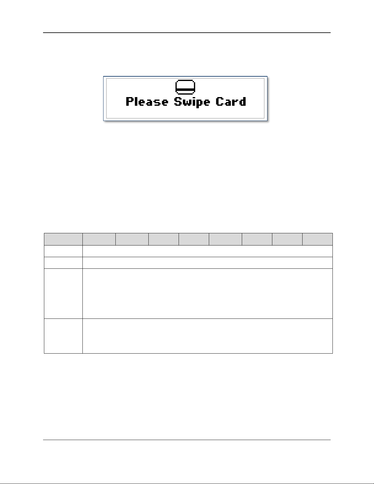
3.4.3 Report 0x03 – Request Swipe Card
This command causes the device to prompt the user to swipe a card by displaying one of four
predetermined messages (see Card Message ID in Table 3-3). Example request screens look like this:
Figure 3-2 - DynaPro Mini Initial Swipe Prompt
The device will report an error in ACKSTS of Report 0x01 – Response ACK in the following cases:
System Error (0x80)
Bad parameter (0x82)
PAN already exists in the device (0x84)
System is not available (0x8A)
When this command completes (card swiped OK, user cancelled, or timeout), the device will send Report
0x22 – Card Status Report to the host. If the Card and Operation Status are both OK, the host should
then send Report 0x0A – Request MSR Data to get the card data.
Table 3-3 - Usage Table for Report 0x03
DynaPro Mini| PIN Encryption Device | Programmer’s Reference (Commands)
Page 30
Page 31

3 - Command Set
Bit
7 6 5 4 3 2 1
0
Byte 0
0x04
Byte 1
Wait Time in seconds, (1 – 255; 0 = 256 seconds)
Byte 2
PIN Mode:
0 = Enter PIN
1 = Enter PIN Amount
2 = Reenter PIN Amount
3 = Reenter PIN
4 = Verify PIN
Byte 3
Max PIN length (<=12)
Min PIN length (>=4)
3.4.4 Report 0x04 – Request PIN Entry
This command causes the device to prompt the user to enter a PIN by displaying one of five
predetermined messages (see PIN Mode in Table 3-4). The messages look like this:
Figure 3-3 - DynaPro Mini Initial PIN Prompt
The device will report an error in ACKSTS of Report 0x01 – Response ACK in the following cases:
Bad parameter (0x82)
System is locked, meaning more than 120 PINs were entered within one hour (0x87)
System is not available (0x8A)
If PIN amount is required, no amount has been sent (0x8B)
If no error occurs, when the command completes (PIN entry done, user cancelled, or timeout), the device
will send Report 0x24 – PIN Response Report to the host using a USB Interrupt IN transaction. If PIN
entry is successful, the report will also contain the PIN KSN (if using a DUKPT PIN Key, otherwise the
PIN KSN will be zero) and the encrypted PIN block (EPB) data. The EPB format will depend on the PIN
option and Session State (see Report 0x20 – Device State Report). If there is no PAN (from card swipe
or sent via command), the EPB will use ISO format 1. If a PAN exists, the PIN option will be used to
determine if the created PIN block will be ISO format 0 or ISO format 3. If the host set the PIN Mode
byte in the command to “Verify PIN,” the device will prompt the user to enter the PIN twice, and will
generate an EPB only if both entries match. The EPB is encrypted under the current PIN DUKPT key as
DES or TDES depending on the injected key type. If the host set the Wait Msg bit in the command’s PIN
Options byte, the device will display a “Please Wait” message during the delay as the unit is checking for
keypad tamper, then will display the Enter PIN message. The most significant nybble of the PIN options
(Byte 5) is RESERVED.
Table 3-4 - Usage Table for Report 0x04
DynaPro Mini| PIN Encryption Device | Programmer’s Reference (Commands)
Page 31
Page 32

3 - Command Set
Bit
7 6 5 4 3 2 1
0
Byte 4
Tones:
0 = No sound
1 = One beep
2 = Two beeps
Byte 5
PIN options
RESERVED
Wait
Msg
Verify
PIN
ISO3
DynaPro Mini| PIN Encryption Device | Programmer’s Reference (Commands)
Page 32
Page 33

3 - Command Set
Bit
7 6 5 4 3 2 1
0
Byte 0
0x05
Byte 1
0
Bit
7 6 5 4 3 2 1
0
Byte 0
0x06
Byte 1
Wait Time in seconds, (1 – 255; 0 = 256 seconds)
Byte 2
Message ID:
0 = Transaction type Credit / Debit
1 = Verify Transaction Amount
2 = Transaction type Credit / Other / Debit
3 = Transaction type Credit / EBT / Debit
4 = Transaction type Credit / Gift/ Debit
5 = Transaction type EBT / Gift / Other
Byte 3
Mask Key:
3.4.5 Report 0x05 – Cancel Command
This command cancels the current command.
Table 3-5 - Usage Table for Report 0x05
3.4.6 Report 0x06 – Request User Selection
This command causes the device to prompt the user to select the transaction type (debit, credit, etc.) or to
verify the transaction amount, as shown below:
Figure 3-4 - DynaPro Mini "Amount OK" User Selection Screen
An error will be reported in ACKSTS of Report 0x01 – Response ACK in the following cases:
Bad parameter (0x82)
System is not available (0x8A)
If transaction amount is required, no amount has been sent (0x8B)
If no error occurs, when the command completes (selection made, user cancelled, or timeout), the device
will do the following:
1) Clear the display
2) Return to the idle state
3) Send Report 0x25 – User Selection Response Report to the host
Table 3-6 - Usage Table for Report 0x06
DynaPro Mini| PIN Encryption Device | Programmer’s Reference (Commands)
Page 33
Page 34

3 - Command Set
Bit
7 6 5 4 3 2 1
0
Enter
Right
Middle
Left
Byte 4
Tones:
Start Transaction Tones Only:
0 = No sound
1 = One beep
2 = Two beeps
Start Transaction & Timeout Tones:
100 = No start beep, no timeout
101 = One start beep, no timeout
102 = Two start beep, no timeout
Bit
7 6 5 4 3 2 1
0
Byte 0
0x07
Byte 1
Wait Time in seconds, (1 – 255; 0 = infinite wait time)
3.4.7 Report 0x07 – Display Message
This command causes the device to display a predefined message for a specified time. Examples are
shown below.
Figure 3-5 - DynaPro Mini Messages
An error will be reported in ACKSTS of Report 0x01 – Response ACK in the following cases:
Bad parameter (0x82)
System is not available (0x8A)
If no error occurs, when the command completes (message displayed, user cancelled, or timeout), the
device will do the following:
1) Clear the display
2) Return to the idle state
3) Send Report 0x27 – Display Message Done Report to the host
Table 3-7 - Usage Table for Report 0x07
DynaPro Mini| PIN Encryption Device | Programmer’s Reference (Commands)
Page 34
Page 35

3 - Command Set
Bit
7 6 5 4 3 2 1
0
Byte 2
Display message ID:
0 = Blank
1 = Approved
2 = Declined
3 = Cancelled
4 = Thank You
5 = PIN Invalid
6 = Processing
7 = Please Wait
8 = Hands Off
9 = PIN PAD not available
10 = Call Your Bank
11 = CARD ERROR
12 = Not Accepted
13 = Processing Error
14 = Use CHIP Reader
15 = Refer to your payment device
Bit
7 6 5 4 3 2 1
0
Byte 0
0x08
Byte 1
0x00
Bit 7 6 5 4
3 2 1
0
Byte 0
0x09
Byte 1
Device Control (default value = 0x00)
3.4.8 Report 0x08 – Request Device Status
This command causes the PIN-PAD to send current information (Session State, Device State and Status,
etc.) to the host using a USB Interrupt IN transaction. Following this command, the host should read an
input report which contains the information (see Report 0x20 – Device State Report).
Table 3-8 - Usage Table for Report 0x08
3.4.9 Report 0x09 – Set Device Configuration
This command, when invoked in Set mode, sends user- or host-defined configuration data to the device.
If the current configuration has been locked, the device will report an error (0x87) in ACKSTS of Report
0x01 – Response ACK and the new configuration will not be set. Otherwise, if the configuration data is
OK, the device will save the new configuration. Important note: Locking can not be undone without
returning the device to the supplier or manufacturer.
When the Config bit is set to unlocked, a user can only change MSR Encryption Variant, Clear Text User
Data, and Beeper Mode in Byte 1, plus Mask Configuration, MSR Card Configuration, Mask Character,
and Number of leading/trailing to leave unmasked.
When the Config bit is set to locked, a user can not change any of the device configuration settings.
Table 3-9 - Usage Table for Report 0x09 (Set mode)
DynaPro Mini| PIN Encryption Device | Programmer’s Reference (Commands)
Page 35
Page 36

3 - Command Set
Bit 7 6 5 4
3 2 1
0
Config
0=unlocked
1=locked
Bitmap
0=unlocke
d
1=locked
Tests
Allowed
0=disable
1=enable
iAP Config
Allowed
0=unlocked
1=locked
Clear
Text
User
Data
0=no
1=yes
0
MSR
encrypt
ion
variant
0=PIN
1=DAT
A
Requir
e auth
0=no
1=yes
Byte 2
Allow Charging in iAP mode
0x00 = disabled, default
0x01 = enabled
Byte 3
Mask Configuration (default value = 0xC0, all enabled except MS2.0)
ISO Mask
0 = disable
1 = enable
Check
Digit
0 = disable
1 = enable
MS2.0 Enable
00 = MS2.0 disabled
10 = MS2.0 enabled
Track 2 Data
Track 1 Data
Error
Blank
Error
Blank
Byte 4
MSR Card Configuration (default value = 0xD5, all enabled)
AAMVA
Card
0 = disable
1 = enable
Nonfinance
card option
Track 3 Data
Track 2 Data
Track 1 Data
00=disabled
01=enabled
11=required
00=disabled
01=enabled
11=required
00=disabled
01=enabled
11=required
Byte 5
Mask Character (factory setting is ‘0’)
Byte 6
Leading length to leave unmasked
In SRED, maximum length = 6
In MS2.0 format, if >8, set to 8; if <5, set to 5
Trailing length to leave unmasked
In SRED, maximum length = 4
Ignored in MS2.0 format
Byte 7
EMV L2 ICS Configuration (Default = 0x01)
Note: This setting is ignored when EMV Mode is disabled.
EMV L2 ICS Configuration
0000 = No L2 capability
0001 = Configuration 1C
0010 = Configuration 2C
0011..1111 = Reserved
Byte 8
0x00
Notes for Byte 3, bits 0 – 3:
These four bits can contain any combination of values from 0000 to 1111.
If Error = 0, the device will build MS2.0 format track data (if MS2.0 is enabled) if at least one track
contains good data – the indicated track may contain errors.
DynaPro Mini| PIN Encryption Device | Programmer’s Reference (Commands)
Page 36
Page 37

3 - Command Set
Bit 7 6 5 4
3 2 1
0
Byte 0
0x09
Byte 1
Device Control (default value = 0x00)
Config
0=unlocked
1=locked
Bitmap
0=unlocked
1=locked
Tests
Allowed
0=disable
1=enable
iAP Config
Allowed
0=unlocked
1=locked
Clear
Text
User
Data
0=no
1=yes
EMV
Mode
0=Ena
bled
1=Dis
abled
MSR
encry
ption
varian
t
0=PI
N
1=DA
TA
Requir
e auth
0=no
1=yes
Byte 2
Allow Charging in iAP mode
0x00 = disabled, default
0x01 = enabled
Byte 3
Mask Configuration (default value = 0xC0, all enabled except MS2.0)
ISO Mask
0 = disabled
1 = enabled
Check Digit
0 = disabled
1 = enabled
MS2.0 Enable
00 = MS2.0 disabled
10 = MS2.0 enabled
Track 2 Data
Track 1 Data
Error
Blank
Error
Blank
Byte 4
MSR Card Configuration (default value = 0xD5, all enabled)
AAMVA
Card
0 = disabled
1 = enabled
Non-finance
card option
Track 3 Data
Track 2 Data
Track 1 Data
00=disabled
01=enabled
11=required
00=disabled
01=enabled
11=required
00=disabled
01=enabled
11=required
Byte 5
Mask Character
Byte 6
Leading length to leave unmasked
In SRED, maximum length = 6
In MS2.0 format, if >8, set to 8; if <5, set to 5
Trailing length to leave unmasked
In SRED, maximum length = 4
Ignored in MS2.0 format
If Error = 1, the device will not build MS2.0 format track data (if MS2.0 is enabled) if the indicated
track contains error(s).
If Blank = 0, the device will build MS2.0 format track data (if MS2.0 is enabled) if at least one track
contains good data – the indicated track may be blank.
If Blank = 1, the device will not build MS2.0 format Track data (if MS2.0 is enabled) if the indicated
track is blank.
3.4.10 Report 0x09 – Get Device Configuration
This command, when invoked in Get mode, will cause the device to send the current device configuration
to the host in the following report format:
Table 3-10 - Usage Table for Report 0x09 (Get mode)
DynaPro Mini| PIN Encryption Device | Programmer’s Reference (Commands)
Page 37
Page 38

3 - Command Set
Bit 7 6 5 4
3 2 1
0
Byte 7
EMV L2 ICS Configuration (Default = 0x01)
Note: This setting is ignored when EMV Mode is disabled.
EMV L2 ICS Configuration
0000 = No L2 capability
0001 = Configuration 1C
0010 = Configuration 2C
0011..1111 = Reserved
Byte 8
0x00
Bit
7 6 5 4 3 2 1
0
Byte 0
0x0A
Byte 1
0x00
Bit
7 6 5 4 3 2 1
0
Byte 0
0x0B
Byte 1
Key ID:
0x00 = PIN key
0x01 = MSR key*
0x02 = PIN Cert
0x03 = MSR Cert
0x04 = Device Authentication signed by PIN cert
0x05 = Device Authentication signed by MSR cert
0x06 = Inject Fixed PIN key signed by PIN cert
0x08 = Inject Authentication key signed by PIN cert
0x09 = Inject Authentication key signed by MSR cert
0x0A = Inject Configuration signed by PIN cert
0x0B = Inject Configuration signed by MSR cert
0x20…0x29 = RESERVED
0x63 = Authentication
0xFF = MFG command
*Note: Use MSR Key when getting challenge to inject Acquirer Master Key
3.4.11 Report 0x0A – Request MSR Data
This command causes the device to send MSR data to the host; it should be issued after a Report 0x03 –
Request Swipe Card command has successfully completed. If the system is not available, the device
will report an error (0x8A) in ACKSTS of Report 0x01 – Response ACK. Otherwise, the device will
send multiple instances of Report 0x23 – Card Data Report to the host. If no MSR data is available,
the device will send a single Report 0x23 – Card Data Report containing a Data Length of 0.
Table 3-11 - Usage Table for Report 0x0A
3.4.12 Report 0x0B – Get Challenge
This command causes the device to send challenge information to the host. The host should first issue the
command in Set mode as follows:
Table 3-12 - Usage Table for Report 0x0B (Set mode)
DynaPro Mini| PIN Encryption Device | Programmer’s Reference (Commands)
Page 38
Page 39

3 - Command Set
Bit
7 6 5 4 3 2 1
0
Byte 0
0x0B
Byte 1
Key ID:
0x00 = PIN key
0x01 = MSR key*
0x02 = PIN Cert
0x03 = MSR Cert
0x04 = Device Authentication signed by PIN cert
0x05 = Device Authentication signed by MSR cert
0x06 = Inject Fixed PIN key signed by PIN cert
0x08 = Inject Authentication key signed by PIN cert
0x09 = Inject Authentication key signed by MSR cert
0x0A = Inject Configuration signed by PIN cert
0x0B = Inject Configuration signed by MSR cert
0x20…0x29 = RESERVED
0x63 = Login/Logout/Authentication
0xFF = MFG command
*Note: Use MSR Key when getting challenge to inject Acquirer Master Key
Byte 2..13
Data block:
If Key_ID < 12 or Key_ID = 0xFF:
Byte 2 – Byte 9 contains the device serial number
Byte 10 – Byte 13 contains the random token
If Key_ID = 0x63 and a valid authentication key is available:
Byte 2 – Byte 9 contains the encrypted partial device serial number and random token
Byte 10 – Byte 13 contains the partial device serial number
Bit
7 6 5 4 3 2 1
0
Byte 0
0x0D
Byte 1
0x00
Byte 2
String length of transaction amount: 1-11
Byte 3
Reserved for future use
After sending this command to the device and getting the ACKSTS report, the host should issue this
command in Get mode. If the key ID is not in the list, or a valid authentication key is not available for
key ID = 0x63, the data block will be all zeros.
Table 3-13 - Usage Table for Report 0x0B (Get mode)
3.4.13 Report 0x0D – Send Session Data - Amount
This command is used to send transaction data (credit or debit card amount) to the device.
An error will be reported in ACKSTS of Report 0x01 – Response ACK in the following cases:
Data error (0x82)
Wrong data length (0x83)
System is not available (0x8A)
Table 3-14 - Usage Table for Report 0x0D (For Amount)
DynaPro Mini| PIN Encryption Device | Programmer’s Reference (Commands)
Page 39
Page 40

3 - Command Set
Bit
7 6 5 4 3 2 1
0
Byte 4..14
Amount data in ASCII format
Byte 15..21
Reserved
Bit
7 6 5 4 3 2 1
0
Byte 0
0x0D
Byte 1
0x01
Byte 2
String length of PAN data: 8-19
Byte 3..21
PAN data in ASCII format
Bit 7 6 5 4 3 2 1 0
Byte 0
0x0E
Byte 1
Info ID (see Table 3-18)
Bit 7 6 5 4 3 2 1 0
Byte 0
0x0E
Byte 1
Info ID (see Table 3-18)
3.4.14 Report 0x0D – Send Session Data - PAN
This command is used to send card PAN data to the device in cases where the PAN is coming from a
source other than the card being processed.
An error will be reported in ACKSTS of Report 0x01 – Response ACK in the following cases:
Data error (0x82)
Wrong data length (0x83)
The PAN already exists (0x84)
System is not available (0x8A)
Table 3-15 - Usage Table for Report 0x0D (For PAN)
3.4.15 Report 0x0E – Get Information
Info ID of Set feature 0x0E selects the requested information.
Table 3-16 - Usage Table for Report 0x0E
The host then uses this command in Get mode to direct the device to return the requested information.
The device will report an error in ACKSTS of Report 0x01 – Response ACK if the system is not
available (0x8A) or the command contains bad parameters (0x82). Otherwise, the device will send an
information feature report to the host, which includes information about the length of the data block found
at the end of the report. See Table 3-18 for assistance interpreting the data block.
Table 3-17 - Usage Table for Report 0x0E
DynaPro Mini| PIN Encryption Device | Programmer’s Reference (Commands)
Page 40
Page 41

3 - Command Set
Bit 7 6 5 4 3 2 1 0
Byte 2
Key Status, if Info ID < 0x80:
0 = Empty (default)
1 = OK
2 = Exhausted
Key Status, if Info ID = 0x80:
0 – 5 = KCV type (see Table 3-18)
Byte 3
Data length (see Table 3-18); default value is 0
Byte
4..63
Block data
Info ID
Key
Status
Data
length
Data
Description
0x00
1
lbllen*
Auth key label
If auth key exists
0x01,0x02
2
20
KSN
If no more keys
0x01
1
20
KSN
PIN key
0x02
1
20
KSN
MSR key
0x03
1
<=59
SN & subject’s DN**
If PIN cert exists
0x04
1
<=59
SN & subject’s DN**
If MSR cert exists
0x05
1
<=19
Label and KCV
If auth key exists
0x06
1
<=19
Label and KCV
If fixed key exists
0x07
1
<=59
List of 2 byte items
(type,MID)
ID list of installed MID secrets
0x08
1
12
Customer ID,
(4 byte integer)
Signing Sequence
Number,
(4 byte integer)
Upgradability Options,
(4 byte integer)
0x0000000 is Generic Customer
Signing Sequence typically starts
at 0x00000000 and must advance
with each upgrade.
Upgradability values:
0x00000000 – Generic Only
0x00000001 – Specific Only
0x00000002 – Generic or
Specific
0x09
1
<=19
Label and KCV
Acquirer Master Key
0x10
1
4 x 3
4 slots for bitmap data
[status + 2 bytes CRC]
status: 0 = not loaded
1 = loaded
Bitmap data status and its CRC
0x20 0x29
- - -
RESERVED
Table 3-18 – Block Data Returned for Report 0x0E
DynaPro Mini| PIN Encryption Device | Programmer’s Reference (Commands)
Page 41
Page 42

3 - Command Set
Info ID
Key
Status
Data
length
Data
Description
0x50
1 9 Keypad sensitivity
Tamper sensitivity
Key on threshold
Key off threshold
4 bytes keypad threshold
Keypad calibration result
Keypad values
0x51
1 8 Parameter1 (2 bytes)
Parameter2 (2bytes)
Z ON pen (1 byte)
Z OFF pen (1 byte)
Reserved for future use
(2 bytes)
Signature Capture configuration
0x60 –
0x70
1
<=59
SN & subject’s DN**
If associated CA cert exists***
0x71 –
0x7F
1
<=59
SN & issuer’s DN**
If associated CA cert exists***
0x80
kcv_type=0
4
KCV value
KCV**** for Auth key
0x80
kcv_type=1
4
KCV value
KCV for PIN key
0x80
kcv_type=2
4
KCV value
KCV for MSR key
0x80
kcv_type=3
4
KCV value
KCV for fixed PIN key
0x80
kcv_type=4
4
Hash value
Dev auth key signed by PIN cert
0x80
kcv_type=5
4
Hash value
Dev auth key signed by MSR cert
0x80
kcv_type=7
6
KCV value
KCV for MID secret
0x80
kcv_type=9
4
KCV value
KCV for Acquirer Master key
0x80
All other
kcv_types
0 KCV****
* lbllen = auth key’s label length
** SN = serial number of cert; DN = distinguished names of subject or issuer of cert; Data length varies
with SN and DN length; max length is 59.
*** its corresponding CA cert
**** KCV = Key Check Value, where the lowest 6 digits are valid
DynaPro Mini| PIN Encryption Device | Programmer’s Reference (Commands)
Page 42
Page 43

3 - Command Set
Bit 7 6 5 4 3 2 1 0
Byte 0
0x0F
Byte 1
0x01 = Login/Authenticate
Byte
2..9
Encrypted random token and device serial number (8 bytes).
See Report 0x0B – Get Challenge.
Bit
7 6 5 4 3 2 1
0
Byte 0
0x0F
Byte 1
0x00 = Logout
Byte 2..9
reserved
3.4.16 Report 0x0F – Login/Authenticate
This command logs in the device.
The following steps are required before issuing this command:
1) Host requests an authentication token from the device (using Report 0x0B – Get Challenge)
2) Host decrypts the received token with the authentication key
3) Host transforms token and encrypts it with the authentication key
In the following cases, authentication will fail and an error will be reported in ACKSTS of Report 0x01 –
Response ACK:
System Error (e.g., a system error or tamper has been detected) (0x80)
No authentication key is found in the device (0x85)
Authentication is locked out (occurs after 3 authentication failures) (0x87)
Host receives an incorrect authentication token (e.g., the decrypted random token or device serial
number doesn’t match the device’s current values) (0x89)
Authentication challenge token times out (i.e. is not used within 5 minutes) (0x8A)
Table 3-19 - Usage Table for Report 0x0F (For Login/Authenticate)
3.4.17 Report 0x0F – Logout
This command logs out the device.
Table 3-20 - Usage Table for Report 0x0F (For Logout)
3.4.18 Report 0x10 – Send Big Block Data to Device
This command is used to provide data for several general commands and input reports (listed in Table
3-21) in 60-byte increments. If the data size is greater than 60 bytes, the data must be split into several
smaller blocks, each containing a maximum of 60 bytes. Two data formats are used in connection with
this command: The first packet (block 0, see Table 3-21) signals the start of a new data set and specifies
the complete length of the data; subsequent packets (blocks 1 through n, see Table 3-22) transmit the
actual data to a predefined buffer within the device.
An error will be reported in ACKSTS of Report 0x01 – Response ACK in the following cases:
The parameters in any block 1 through n data packet don’t match (or don’t follow) the previous data
packet’s parameters (0x82)
DynaPro Mini| PIN Encryption Device | Programmer’s Reference (Commands)
Page 43
Page 44

3 - Command Set
Bit
7 6 5 4 3 2 1
0
Byte 0
0x10
Byte 1
Data Type:
0x06 = Request user selection user-defined message
0x07 = Display message user defined
0x0C = Bitmap image data
0x17 = Firmware file
0xA0 = EMV data in DOL format (MAC)
0xA1 = EMV data in TLV format, Set EMV Tag(s) (MAC)
0xA4 = EMV data in TLV format, Acquirer Response (ARPC)
0xA5 = CA Public Key Data (MAC)
0xA7 = C-APDU (Secured)
Byte 2
0 = Start of new data set (this packet contains the total data length)
Byte 3
Data Length – low byte (legacy)
Byte 4
Data Length – high byte (legacy) , Data length middle low byte
Byte 5
Data Length – middle high byte
Byte 6
Data Length – high byte
Byte 7
Extended Type: 0= <64K(legacy), 1=>64K
Byte 8..63
reserved
Bit
7 6 5 4 3 2 1
0
Byte 0
0x10
Byte 1
Data type:
0x06 = Request User Selection User Defined Message
0x07 = Display Message User Defined
0x0C = Bitmap image data
0x17 = Firmware file
0xA0 = EMV data in DOL format (Secured)
0xA1 = EMV data in TLV format
0xA4 = EMV data in TLV format, Acquirer Response (ARPC)
0xA5 = CA Public Key Data (MAC)
0xA7 = C-APDU (Secured)
Byte 2
Data packet number (1…n)
Data length error (e.g., the data size is 0 or is larger than the available buffer size) (0x83)
If the command is successful, the bitmap image or key handling/manufacturing command will be stored
in a predefined buffer within the device.
If the Data Type byte is set to one of the types tagged “Secured,” the first 2 bytes of the data packet
should be the expected length of the message after decryption.
Table 3-21 – Usage Table for Report 0x10 (Block 0)
Table 3-22 – Usage Table for Report 0x10 (Blocks 1 through n)
DynaPro Mini| PIN Encryption Device | Programmer’s Reference (Commands)
Page 44
Page 45

3 - Command Set
Bit
7 6 5 4 3 2 1
0
Byte 3
Packet length
Byte 4..63
Packet data:
For EMV data, use Tag-Length-Value format [for examples, see section 3.3 About
Commands Tagged As “MAC”]
Bit
7 6 5 4 3 2 1
0
Byte 0
0x11
3.4.19 Report 0x11 – Request Manual Card Entry
This command causes the device to prompt the user to enter the following card information by keypad.
Two modes are available: Account Number mode and Qwick Code mode:
Account Number mode prompts for the following:
Account number (minimum length = 9, maximum length = 19)
Expiration date (minimum length = maximum length = 4)
Card verification code (minimum length = 3, maximum length = 4)
Qwick Code mode prompts for the following:
Qwick Code (minimum length = 8, maximum length = 16)
Last 4 digits of account # (minimum length = maximum length = 4)
Card verification code (minimum length = 3, maximum length = 4)
Figure 3-6 - DynaPro Mini Manual Card Information Entry
An error will be reported in ACKSTS of Report 0x01 – Response ACK if the device status is not OK
(0x8A).
If the command completes successfully, Report 0x22 – Card Status Report will be sent back to the
host. If the host or user cancelled the request, or if the request timed out, byte 1 of Report 0x22 – Card
Status Report will contain the appropriate Operation Status code to indicate why the command did not
complete. Otherwise, if all of the card information was entered correctly, byte 1 = 0x00 (this command
completed OK), byte 2 = 0x00 (Card Status is OK), byte 3 = 0x03 (Card Type is manual), and the host
should send a request to get the card data (see Report 0x0A – Request MSR Data). If Card and
Operation Status are both OK, the host should send a request to get the card data. Report 0x20 – Device
State Report will also be sent back to update the current Device State.
Table 3-23 – Usage Table for Report 0x11
DynaPro Mini| PIN Encryption Device | Programmer’s Reference (Commands)
Page 45
Page 46

3 - Command Set
Bit
7 6 5 4 3 2 1
0
Byte 1
Wait Time in seconds, (1 – 255; 0 = 256 seconds)
Byte 2
0 0 0
0=Use PAN min
9, max 19
1=Use PAN min
14, max 21
1=Use
PAN in
PIN
block
creation
1=Use
Qwick
Codes
entry
Field Options:
0 = Acct,Date,CVC
1 = Acct,Date
2 = Acct,CVC
3 = Acct
Byte 3
Tones:
0 = No sound
1 = One beep
2 = Two beeps
The track data sent by the device for manually entered card data may be masked according to the device’s
configuration (the same as it is for credit/debit cards), but the data shown in the following examples is
unmasked just to show the detail. The account number or QwickCode is denoted by a string of 5s, the
expiration date (or PAN4) by 3s and the CVC by 4s. The location marked by ‘6’ indicates the field
options used when the data was collected – unused fields will be 0s. 0s below denote fixed-length filler.
Track 1 card type (‘B’ for credit/debit cards) is set to ‘M’ and the name is set to the string literal
“MANUAL ENTRY/”.
Track 1 data may be found in the Card Report (see Report 0x23 – Card Data Report) that contains Data
ID = 0x01. The device will format Track 1 card data as follows:
%M5555555555555555^MANUAL ENTRY/^33330000004444000006?
Track 2 data may be found in the Card Report (see Report 0x23 – Card Data Report) that contains Data
ID = 0x02. The device will format Track 2 card data as follows:
;5555555555555555=33330000004444006?
The device does not change the length of the CVC (either 3 or 4 characters) entered by the user. The
length of the CVC thus affects the length of the track data output by the device, and the host must locate
the CVC in the track data as follows: The CVC starting position is the byte after the 6 digits which
follow the 4-digit expiration date (or PAN4). The CVC ending position in Track 1 is the byte before the 6
digits which precede the end sentinel (?); the CVC ending position in Track 2 is the byte before the 3
digits which precede the end sentinel (?).
3.4.20 Report 0x14 – Request User Data Entry
This command causes the device to prompt the user to enter SSN, Zip Code, or Birth Date by displaying
one of four predetermined messages.
An error will be reported in ACKSTS of Report 0x01 – Response ACK in the following cases:
Bad parameter (0x82)
System is not available (0x8A)
Otherwise, when the command completes (data entry done, user cancelled, or timeout), the device will
send Report 0x21 – User Data Entry Response Report to the host using a USB Interrupt IN
DynaPro Mini| PIN Encryption Device | Programmer’s Reference (Commands)
Page 46
Page 47

3 - Command Set
Bit
7 6 5 4 3 2 1
0
Byte 0
0x14
Byte 1
Wait time in seconds, (1 – 255; 0 = 256 seconds)
Byte 2
User data mode:
0 = Enter SSN (9 digits)
1 = Enter Zip code (5 digits)
2 = Enter Birthdate (8 digits, in MM/DD/YYYY format)
3 = Enter Birthdate (6 digits, in MM/DD/YY format)
Byte 3
Tones:
0 = No sound
1 = One beep
2 = Two beeps
Bit 7 6
5
4 3 2 1 0
Byte 0
0x1A
Byte 1
Mode
0 – Product_ID
1 – Maximum Application Message Size
2 – Capability String
3 – Manufacturer
4 – Product Name
5 – Serial Number
6 – Firmware Number
7 – Build Info
A – Boot1 Firmware Version
B – Boot2 Firmware Version
Byte 2..63
Reserved
Bit 7 6 5 4 3 2 1 0
Byte 0
0x1A
Byte 1
0x00
transaction. If data entry is successful, the report will also contain the MSR KSN and the encrypted user
data block (EUDB). The EUDB format is similar to the PIN ISO format 1 data block. The EUDB is
encrypted using X9.24 data variant under the current data variant derived from the MSR key.
Table 3-24 – Usage Table for Report 0x14
3.4.21 Report 0x1A – Request Device Information
This command requests information about the device.
Table 3-25 – Usage Table for Report 0x1A
Depending on what device information the host has requested, the device will respond to this command
using the following formats.
Table 3-26 - Usage Table for Report 0x1A - Product_ID
DynaPro Mini| PIN Encryption Device | Programmer’s Reference (Commands)
Page 47
Page 48

3 - Command Set
Bit 7 6 5 4 3 2 1 0
Byte 2..63
“3004” (null terminated string)
Bit 7 6 5 4 3 2 1 0
Byte 0
0x1A
Byte 1
0x01
Byte 2 to 63
“64” (null terminated string)
Bit 7 6 5 4 3 2 1 0
Byte 0
0x1A
Byte 1
0x02
Byte 2..63
“V=4,SC=0,MS2=1,PFK=1,UDE=0,CE=2" (null terminated string)
Bit 7 6 5 4 3 2 1 0
Byte 0
0x1A
Byte 1
0x03
Byte 2..63
“MagTek, Inc.” (null terminated string)
Bit 7 6 5 4 3 2 1 0
Byte 0
0x1A
Byte 1
0x04
Byte 2..63
The product name is a null-terminated string containing “DynaPro Mini”
Bit 7 6 5 4 3 2 1 0
Byte 0
0x1A
Byte 1
0x05
Byte 2..63
“12345678” (null terminated string)
Table 3-27 - Usage Table for Report 0x1A - Maximum Application Message Size
Table 3-28 - Usage Table for Report 0x1A – Capability String
Table 3-29 - Usage Table for Report 0x1A - Manufacturer
Table 3-30 - Usage Table for Report 0x1A - Product Name
Table 3-31 - Usage Table for Report 0x1A - Serial Number
DynaPro Mini| PIN Encryption Device | Programmer’s Reference (Commands)
Page 48
Page 49

3 - Command Set
Bit 7 6 5 4 3 2 1 0
Byte 0
0x1A
Byte 1
0x06
Byte 2..63
“30050856A01-DEMO” (null terminated string)
Bit 7 6 5 4 3 2 1 0
Byte 0
0x1A
Byte 1
0x07
Byte 2..63
“<date><time>” (null terminated string)
Bit 7 6 5 4 3 2 1 0
Byte 0
0x1A
Byte 1
0x0A
Byte 2..63
“30050858B01-DEMO” (null terminated string)
Bit 7 6 5 4 3 2 1 0
Byte 0
0x1A
Byte 1
0x0B
Byte 2..63
“30050866B02-DEMO” (null terminated string)
Table 3-32 - Usage Table for Report 0x1A - Firmware Number
Table 3-33 - Usage Table for Report 0x1A – Build Info
Table 3-34 - Usage Table for Report 0x1A - Boot1 Firmware Version
Table 3-35 - Usage Table for Report 0x1A - Boot2 Firmware Version
DynaPro Mini| PIN Encryption Device | Programmer’s Reference (Commands)
Page 49
Page 50

3 - Command Set
Bit 7 6 5 4 3 2 1 0
Byte 0
0x1C (report identifier)
Byte 1
Reserved,
set to 0
Reserved,
set to 0
Reserved,
set to 0
Reserved,
set to 0
Reserved,
set to 0
Ready
Suspend
Power
down
Byte 2
Reserved, set to 0x00
Byte 3
Reserved, set to 0x00
Byte 4
Reserved, set to 0x00
3.4.22 Report 0x1C – Set/Get BLE Power Configuration (BLE Only)
This command sets or gets the BLE power configuration, depending on whether it is called in Set mode or
Get mode.
Table 3-36 – Usage Table for Report 0x1C
Power Down: (Read/Write)
0: The device is not powered down.
1: The device is powered down.
Powering down the device will conserve power. The host will have limited communications capability
with the device when it is powered down. During this time, only this report can be get or set. Powering
the device down will conserve more power than suspending it. It takes more time to power the device up
than it does to take it out of suspend.
Suspend: (Read/Write)
0: The device is not suspended.
1: The device is suspended.
Suspending the device will conserve power. The host will have limited communications capability with
the device when it is suspended. During this time, only this report can be get or set. Powering the device
down will conserve more power than suspending it. It takes more time to power the device up than it
does to take it out of suspend.
Ready: (Read only, always write 0)
0: The device is not ready.
1: The device is ready.
The host will have limited communications capability with the device when it is powered down or
suspended. During this time, only this report can be get or set. Since it takes some time for the device to
be capable of full communications after powering it up or taking it out of suspend, this flag can be read to
determine if the device is ready for full communications or not.
3.4.23 Report 0x1D – Set BLE Module Control Data (BLE Only)
This command sends control data to the BLE module, which controls BLE communications. The device
will first respond with Report 0x01 – Response ACK. After the BLE module control data is processed,
the device will respond with Report 0x2D –BLE Module Control Data (BLE Only). It is important to
understand that even though this is implemented as a feature report to be used in Set mode, it can be used
to send requests to discover the current property settings in the BLE module. The full set of BLE module
controls can be found in Appendix J BLE Module Control Data.
DynaPro Mini| PIN Encryption Device | Programmer’s Reference (Commands)
Page 50
Page 51

3 - Command Set
Bit
7 6 5 4 3 2 1
0
Byte 0
0x1D (report identifier)
Byte 1
Control data length (defined in Appendix J)
Byte 2 to
(2+control
data length-1)
Control data (defined in Appendix J)
Byte (2 +
control data
length) to 63
Padding. Set all bytes to zero.
Bit
7 6 5 4 3 2 1
0
Byte 0
0x1E (report identifier)
Byte 1
0 – Set Bundle Seed ID (10 bytes)
1 – Set reverse DNS (variable, up to 50 bytes)
Byte 2
Data Length
Byte 3..63
Data
Bit
7 6 5 4 3 2 1
0
Byte 0
0x1E (report identifier)
Byte 1
Length of Bundle Seed ID, normally 0x0A (<=0x0A)
Byte 2..11
Bundle Seed ID, high bytes padded with 0x00 if length is less than 0x0A
Byte 12
Reverse DNS Length (<= 0x32)
Byte 13..63
Reverse DNS, high bytes padded with 0x00 if length is less than 0x32
Table 3-37 – Usage Table for Report 0x1D
3.4.24 Report 0x1E – Set iAP Protocol Info (30-pin Only)
When the host calls this command in Set mode, it sets iAP related data in the device.
Table 3-38 – Usage Table for Report 0x1E (Set mode)
3.4.25 Report 0x1E – Get iAP Protocol Info (30-pin Only)
When the host calls this command in Get mode, it retrieves the current device iAP protocol Bundle Seed
ID and reverse DNS in the following report format:
Table 3-39 – Usage Table for Report 0x1E (Get mode)
3.4.26 Report 0x1F – Request Clear Text User Data Entry
This command directs the device to prompt the user to enter his or her SSN, Zip Code, or Birth Date by
displaying predetermined messages. It is only available in firmware revision C12 or newer.
An error will be reported in ACKSTS of Report 0x01 – Response ACK in the following cases:
Bad parameter (0x82)
System is not available (0x8A)
DynaPro Mini| PIN Encryption Device | Programmer’s Reference (Commands)
Page 51
Page 52

3 - Command Set
Bit
7 6 5 4 3 2 1
0
Byte 0
0x1F
Byte 1
Wait time in seconds, (1 – 255; 0 = 256 seconds)
Byte 2
User data mode:
0 = Enter SSN (9 digits)
1 = Enter Zip code (5 digits)
2 = Enter Birthdate (8 digits, in MM/DD/YYYY format)
3 = Enter Birthdate (6 digits, in MM/DD/YY format)
Byte 3
Tones:
0 = No sound
1 = One beep
2 = Two beeps
Bit
7 6 5 4 3 2 1
0
Byte 0
0x030
Byte 1
Key ID:
0x00 = MSR DUKPT key KSN
Bit
7 6 5 4 3 2 1
0
Byte 0
0x30
Byte 1
Key ID:
0x00 = MSR DUKPT key KSN
Otherwise, when the command completes (data entry done, user cancelled, or timeout), the device will
send Report 0x2E – Clear Text User Data Entry Response Report to the host using a USB Interrupt
IN transaction. If data entry is successful, the report will also contain the requested data.
Table 3-40 – Usage Table for Report 0x1F
3.4.27 Report 0x30 – Set / Get KSN
When called in Set mode, this command causes the device to generate a KSN data for transmission to a
host.
Table 3-41 – Usage Table for Report 0x30 (Set mode)
After sending this command to the device and getting the ACKSTS report, issue the same command in
Get mode for the KSN Feature Report (see Table 3-42). If a valid DUKPT key is not available, the data
block will be all zeros.
The KSN reported is only valid for 1 minute. Report 0x31 – Set KSN Encrypted Data should be sent
within the timeout period.
This feature is used for the Token Reversal Function.
Table 3-42 – Usage Table for Report 0x30 (Get mode)
DynaPro Mini| PIN Encryption Device | Programmer’s Reference (Commands)
Page 52
Page 53

3 - Command Set
Bit
7 6 5 4 3 2 1
0
Byte 2..11
Data block:
Byte 2 – Byte 11 contain the KSN
Byte 12..19
Device Serial Number
Byte 20..23
Padding
Byte 24..27
CBC-MAC
Bit
7 6 5 4 3 2 1
0
Byte 0
0x31
Byte 1
Display Time in seconds, (1 – 255; 0 = 256 seconds)
3.4.28 Report 0x31 – Set KSN Encrypted Data
Before using this command, the host must have already used Report 0x30 – Set / Get KSN to retrieve
the MSR dukpt KSN from the device. Then the host must use Report 0x10 – Send Big Block Data to
Device to send encrypted PAN data to the device, in the following format:
AAAA /* 2-byte MSB message length excluding padding and CBC-MAC */
F9<len> /* container for MAC structure and generic data */
DFDF54(MAC KSN)<len><val>
DFDF55(MAC Encryption Type)<len><val>
DFDF25(IFD Serial Number)<len><val>
FA<len>/* container for generic data */
DFDF44 (Encrypted PAN data)<len><val>
(Buffer if any to be a multiple of 8 bytes)
CBC-MAC (4 bytes, use MAC variant of MSR dukpt key)
The host can then use this command to process data in the big block. The device decrypts and displays
the data until the display timeout expires.
This feature is used for the Token Reversal Function.
The value of DFDF44 is always encrypted under the data variant of the MSR dukpt key.
Responses:
OK, ACKSTS = 0
Bad CBC-MAC ACKSTS = 0x82
Wrong Serial Number, ACKSTS = 0x82
Table 3-43 – Usage Table for Report 0x31
DynaPro Mini| PIN Encryption Device | Programmer’s Reference (Commands)
Page 53
Page 54

3 - Command Set
Bit
7 6 5 4 3 2 1
0
Byte 0
0x32
Byte 1
0x00
Bit 7 6 5 4 3 2 1 0
Byte 0
0x32
Byte 1
Number of bytes to follow (36 for the 6 slots)
Byte 2..7
Data on BIN Table Slot 1
Byte 8..13
Data on BIN Table Slot 2
Byte 14..19
Data on BIN Table Slot 3
Byte 20..25
Data on BIN Table Slot 4
3.4.29 Report 0x32 – Set BIN Table Data (MAC)
The device provides six slots in the BIN table to hold BINs. Each slot holds 6 digits. After a cardholder
swipes a card, the device will check the BIN table to see if it contains the card’s BIN. If it finds the
card’s BIN and if the card’s PAN length is 19 characters or longer, it will not encrypt data ID 4, 5 or 6 in
the Report 0x23 – Card Data Report it sends to the host.
Report 0x10 – Send Big Block Data to Device is first used to send BIN table data to the device, in the
following format [use the Acquirer Master Key (AMK) to calculate CBC-MAC]:
AAAA /* 2-byte MSB message length excluding padding and CBC-MAC */
F9<len> /* container for MAC structure and generic data */
DFDF55(MAC Encryption Type)<len><val>
DFDF25(IFD Serial Number)<len><val>
FA<len>/* container for generic data */
DFDF61(BIN Table Slot1)<6><val>
DFDF62(BIN Table Slot2)<6><val>
DFDF63(BIN Table Slot3)<6><val>
DFDF64(BIN Table Slot4)<6><val>
DFDF65(BIN Table Slot5)<6><val>
DFDF66(BIN Table Slot6)<6><val>
(Padding if any to be a multiple of 8 bytes)
CBC-MAC (4 bytes, use MAC variant of AMK)
Table 3-44 – Usage Table for Report 0x32 (Set mode)
An error will be reported in ACKSTS of Report 0x01 – Response ACK in the following cases:
Bad parameter (0x82)
System is not available (0x8A)
3.4.30 Report 0x32 – Get BIN Table Data
This command will cause the device to send the current contents of the BIN table to the host in the
following report format:
Table 3-45 – Usage Table for Report 0x32 (Get mode)
DynaPro Mini| PIN Encryption Device | Programmer’s Reference (Commands)
Page 54
Page 55

3 - Command Set
Bit 7 6 5 4 3 2 1 0
Byte 26..31
Data on BIN Table Slot 5
Byte 32..37
Data on BIN Table Slot 6
Bit
7 6 5 4 3 2 1
0
Byte 0
0xFF
Byte 1
0 – Soft Reset
Byte 2
Reserved
Bit
7 6 5 4 3 2 1
0
Byte 0
0x20
Byte 1
Device State (see Appendix C Status and Message Table)
Byte 2
Session State (see Appendix C Status and Message Table)
Byte 3
Device Status (see Appendix C Status and Message Table)
Byte 4
Device Certificate Status (see Appendix C Status and Message Table)
Byte 5
Hardware Status (see Appendix C Status and Message Table)
Byte 6
ICC Master and Session Key Status
Bit 0: 1 = No Acquirer Master Key Injected
Bit 1: 1 = No ICC Session Key Active
Bit 2: 1 = CAPK EMV database corrupted
Bit 3: 1 = Terminal/Payment Brand EMV Database corrupted
Bit 4: 1 = Card Present in smart card connector
An error will be reported in ACKSTS of Report 0x01 – Response ACK in the following cases:
Bad parameter (0x82)
System is not available (0x8A)
3.4.31 Report 0xFF – Device Reset
This command causes the device to perform a restart.
Table 3-46 – Usage Table for Report 0xFF
3.5 General Input Reports
Input reports are asynchronous data packets (i.e., events) sent from the device to the host using a USB
Interrupt IN transaction. Events occur when the device state changes or when an asynchronous command
(such as a command that requires user input) has completed.
3.5.1 Report 0x20 – Device State Report
This event is triggered explicitly when the host successfully issues Report 0x08 – Request Device
Status, or automatically when the device changes state. Both cases cause the device to send Device State,
Session State, Device Status, Device Certificate Status, and Hardware Status to the host.
Table 3-47 - Usage Table for Report 0x20
DynaPro Mini| PIN Encryption Device | Programmer’s Reference (Commands)
Page 55
Page 56

3 - Command Set
Bit
7 6 5 4 3 2 1
0
Byte 0
0x21
Byte 1
Operation Status (see Appendix C Status and Message Table)
Bytes 2..11
MSR KSN
Bytes 12..19
Encrypted User Data block
Bits
0-3 4-7 8-
11
12
15
16
19
20
23
24
27
28
31
32
35
36
39 4043 4447
48
51
52
55
56
59
60
63
SSN
C N P P P P P P P P P R R R R
R
Zip
code
C N P P P P P R R R R R R R R
R
Birth
date
C N P P P P P P P/R P/R R R R R R
R
Bit 7 6 5 4 3 2 1 0
Byte 0
0x22
Byte 1
Operation Status (see Appendix C Status and Message Table)
Byte 2
Card Status (see Appendix C Status and Message Table)
3.5.2 Report 0x21 – User Data Entry Response Report
This event supports Report 0x14 – Request User Data Entry. After the user has successfully entered
data, the device uses this report to send user data to the host.
Table 3-48 - Usage Table for Report 0x21
The User Data block contains the information that was requested by the host with Report 0x14 –
Request User Data Entry (for example, if the host requested the user’s zip code, this report would return
just the zip code data). The 8-byte User Data block is divided into 16 four-bit nybbles, as specified in the
tables below. Each nybble contains one of the following:
C: Control field (0100=SSN; 0101=Zip Code; 0110=Birth Date
N: Data length
P: User data digit from 0000 (decimal 0) to 1001 (decimal 9)
R: Filled random number
P/R: If the Birth Date data length is 6 (mmddyy format), the positions marked P/R will be filled with
random numbers (R); if the Birth Date data length is 8 (mmddyyyy format), those positions will
contain the rightmost two characters of the birth year (P).
Table 3-49 - Report 0x21 User Data Block Format
3.5.3 Report 0x22 – Card Status Report
This event is triggered by Report 0x03 – Request Swipe Card or Report 0xA2 – Request Start EMV
Transaction, which will cause the device to send Operation Status, Card Status, and Card Type to the
host.
Table 3-50 - Usage Table for Report 0x22
DynaPro Mini| PIN Encryption Device | Programmer’s Reference (Commands)
Page 56
Page 57

3 - Command Set
Bit 7 6 5 4 3 2 1 0
Byte 3
Card Type (see Appendix C Status and Message Table)
Bit
7 6 5 4 3 2 1
0
Byte 0
0x23
Byte 1
Data ID:
0x01 = Track 1 data
0x02 = Track 2 data
0x03 = Track 3 data
0x04 = Encrypted Track 1 data
0x05 = Encrypted Track 2 data
0x06 = Encrypted Track 3 data
0x07 = Encrypted MagnePrint data
0x40 = Encrypted PAN and expiration date (financial cards only; otherwise data is
blank)
0x41 = Device serial number
0x63 = KSN and MagnePrint Status
0x64 = CBC-MAC
Byte 2
Track Status:
0x00 = OK
0x01 = Empty
0x02 = Error
0x03 = Disabled
Byte 3
Data length
Byte 4
Data block
If Data ID < 0x08, data is track, encrypted track, or MP data corresponding to its data
ID
If Data ID = 0x63, Bytes 4 -13 are KSN data; bytes 14-17 are MP Status data
If Data ID = 0x41, data is 8 byte serial number
If Data ID = 0x64, data is 4 byte CBC-MAC
If Data ID = 0x40, data is encrypted PAN and Expiration date in the following format:
Start Sentinel(‘;’)
PAN
Separator (‘=’)
YYMM
(‘?’)
3.5.4 Report 0x23 – Card Data Report
This event is triggered by Report 0x0A – Request MSR Data, which causes the device to send eight
reports to the host for each successful card swipe or manual card entry.
Table 3-51 - Usage Table for Report 0x23
If the device has been configured to use the MS2.0 masking configuration (see Report 0x09 – Get
Device Configuration), then track status (byte 2) of Data ID 0x63 uses a different set of status values,
defined as follows:
DynaPro Mini| PIN Encryption Device | Programmer’s Reference (Commands)
Page 57
Page 58

3 - Command Set
Value
Track Status If Using MS2.0
0x00
SUCCESS
0x01
N/A
0x02
NO_TK2_FS
0x03
BAD_TK2_PAN_LEN
0x04
NO_FIRST_TK1_FS
0x05
NO_SECOND_TK1_FS
0x06
NO_TK1_ES
0x07
NO_TK2_ES
0x08
TK1_TRAIL_TOO_SHORT
0x09
TK1_AND_TK2_PANS_NOT_EQUAL
0x0A
BAD_TK1_FC
0x0B
DATA_NOT_ASCII_DECIMAL
0x0C
BAD_TK2_PAN_PREFIX
0x0D
BAD_ADDITIONAL_DATA
0x0E
TK1_LEN_TOO_LONG
0x0F
DATA_PROHIBITED_CHARS
0x10
TK1_BLANK
0x11
TK1_ERROR
0x12
TK2_BLANK
0x13
TK2_ERROR
0x14
NOTRACKDATA
0x15
TK1_PANTOOSHORT
Bit
7 6 5 4 3 2 1
0
Byte 0
0x24
Byte 1
Operation Status (see Appendix C Status and Message Table)
Table 3-52 - Report 0x23 Track Status Byte When Using MS2.0 Masking
3.5.5 Report 0x24 – PIN Response Report
This event is triggered by Report 0x04 – Request PIN Entry, which causes the device to send PIN data
to the host after a PIN is successfully entered.
The device may report ‘Keypad Security’ in Byte 1 to indicate the keypad has detected a tamper
condition. This can be triggered by a user pressing a function key for too long when selecting an account
type. To cover this case, the software should include retry logic that resends Report 0x04 – Request PIN
Entry to re-arm the PIN pad.
Table 3-53 - Usage Table for Report 0x24
DynaPro Mini| PIN Encryption Device | Programmer’s Reference (Commands)
Page 58
Page 59

3 - Command Set
Bit
7 6 5 4 3 2 1
0
Bytes 2..11
PIN KSN. If fixed PIN key is used, KSN is zero.
Bytes 12..19
Encrypted PIN block
Bit
7 6 5 4 3 2 1
0
Byte 0
0x25
Byte 1
Operation Status (see Appendix C Status and Message Table)
Byte 2
Code of key pressed:
0x71 = left function key
0x72 = middle function key
0x74 = right function key
0x78 = ENTER key
Bit
7 6 5 4 3 2 1
0
Byte 0
0x27
Byte 1
Operation Status
Bit
7 6 5 4 3 2 1
0
Byte 0
0x29
3.5.6 Report 0x25 – User Selection Response Report
This event is triggered when the user is asked to choose an account type, which causes the device to send
the user’s response (i.e. the key pressed) to the host.
Table 3-54 - Usage Table for Report 0x25
3.5.7 Report 0x27 – Display Message Done Report
This event is sent by the device to the host to indicate a pending Report 0x07 – Display Message has
completed.
Table 3-55 - Usage Table for Report 0x27
3.5.8 Report 0x29 – Send Big Block Data to Host
This event is used by the device to send the user’s signature, device certificate, or CSR to the host. If the
data size is greater than 123 bytes, the data must be broken into multiple 123-byte data blocks, or packets.
Three data formats are used in connection with this command:
The first packet (block 0) is used to signal the start of sending, which defines the buffer type, buffer
status, and the total length of data being sent (in bytes);
Subsequent packets (blocks 1 through n) contain the requested data; and
A final packet signifies the end of sending.
If the big buffer type is SECURED or MAC, the first 2 bytes of the data packet are the expected data
length after decryption.
Table 3-56 - Start of Big Block Sending Format (Block 0)
DynaPro Mini| PIN Encryption Device | Programmer’s Reference (Commands)
Page 59
Page 60

3 - Command Set
Bit
7 6 5 4 3 2 1
0
Byte 1
Big buffer type:
0x00 = Signature capture data
0x02 = Device cert
0x18 = Perform Test (0x18) APDU
0x32 = Set BIN
0x42 = CSR
0xA1 = EMV data in TLV format, Tag Data (MAC)
0xA2 = RESERVED
0xA3 = RESERVED
0xA4 = EMV data in TLV format, Authorization Request (ARQC)
0xA5 = CA Public Key (MAC)
0xA6 = ATR (Secured)
0xA7 = R-APDU (Secured)
0xAB = EMV data in TLV format, Batch Data or Batch Data and Reversal Data
Byte 2
0x00 = Start flag
Byte 3
Big buffer status (0x00 = N/A)
Byte 4
Data length–low byte
Byte 5
Data length–high byte
Bit
7 6 5 4 3 2 1
0
Byte 0
0x29
Byte 1
Not defined
Byte 2
Block number (options: 1 – 98)
Byte 3
Data length
Byte 4..n
Data block (maximum 123 bytes)
Bit
7 6 5 4 3 2 1
0
Byte 0
0x29
Byte 1
Not defined
Byte 2
99 = End flag
Table 3-57 - Big Block Data Sending Format (Blocks 1 thru n)
Table 3-58 - End of Big Block Sending Format
3.5.8.1 Big Block Data for Authorization Request (ARQC)
When an ONLINE approval is required as determined by the device and the ICC, the authorization
request message will be in the format shown below. Data in the big block will use the EMV tag 70 as a
container tag (70 <LEN> <TLV TLV…TLV>) for the data listed in the table below, or as configured by
tag DFDF02.
DynaPro Mini| PIN Encryption Device | Programmer’s Reference (Commands)
Page 60
Page 61

3 - Command Set
Tag
Description
Source
Format
Length
9F03
Secondary amount associated with the
transaction representing a cash back amount
Device
n
6
9F26
Cryptogram returned by the ICC in response of
the GENERATE AC command
Card
b
8
82
Application Interchange Profile
Card
b 2 5A
Application PAN
Card
c
0-10
5F34
Application PAN Sequence Number
Card
n 1 9F36
Application Transaction Counter
Card
b
2
9F1A
Terminal Country Code
Device
n
2
95
TVR
Device
b
5
9F02
Authorized amount of the transactions
(excluding adjustments)
Device
n
6
5F2A
Transaction Currency Code
Device
n
2
9A
Local Date transaction was authorized
Device
n 3 9C
Transaction Type
Device
n 1 9F37
Unpredictable Number
Device
b 4 9F10
Issuer Application Data
Card
b
0-32
DFDF53
Fallback Indicator
Device
n
1
F5
Container For Encrypted PIN
Device
b
Var
F4
Container For Encrypted MSR
Device
b
Var
Bit
7 6 5 4 3 2 1
0
Byte 0
0x2A
Byte 1
Status of Command (“ACKSTS”)
Byte 2
ID for Command reporting status
Byte 3..n
Reserved
3.5.9 Report 0x2A – Delayed Response ACK
This event is triggered by completion of longer-running commands that need to report status back to the
host. It is an asynchronous version of Report 0x01 – Response ACK.
Table 3-59 - Usage Table for Report 0x2A
3.5.10 Report 0x2B – Test Response
Reserved.
3.5.11 Report 0x2D –BLE Module Control Data (BLE Only)
This input report event is triggered by completion of Report 0x1D – Set BLE Module Control Data
(BLE Only) after the device returns Report 0x01 – Response ACK and processes the control data.
DynaPro Mini| PIN Encryption Device | Programmer’s Reference (Commands)
Page 61
Page 62

3 - Command Set
Byte
Description
Byte 0
0x2D
Byte 1
Control data length (defined in Appendix J)
Bytes 2 to (2
+ control data
length – 1)
Control data (defined in Appendix J)
Bytes (2 +
control data
length) to 63
Padding. All bytes are zeros.
Byte
Description
Byte 0
0x2E
Byte 1
Operation Status (see Appendix C Status and Message Table)
Byte 2
User Data Mode
0 = SSN (9 digits)
1 = Zip Code (5 digits)
2 = Birthdate (8 digits, MMDDYYYY format)
3 = Birthdate (6 digits, MMDDYY format)
Byte 3
Length of data
Bytes 4 – 12
Clear Text User Data block – only the indicated number of bytes is meaningful, other
bytes should be ignored.
Important usage notes regarding getting and setting BLE module properties are included in section 3.4.23
Report 0x1D – Set BLE Module Control Data (BLE Only).
Table 3-60 - Usage Table for Report 0x2D
3.5.12 Report 0x2E – Clear Text User Data Entry Response Report
This event is triggered by Report 0x1F – Request Clear Text User Data Entry, which causes the device
to send clear text User data to the host after the user has successfully entered data. It is only available in
firmware revision C12 or newer.
Table 3-61 - Usage table for Report 0x2E
DynaPro Mini| PIN Encryption Device | Programmer’s Reference (Commands)
Page 62
Page 63

3 - Command Set
Bit 7 6 5 4 3 2 1 0
Byte 0
0x2C
Byte 1
EMV Cardholder Interaction Status ID:
0x01 = Waiting for amount confirmation selection
0x02 = Amount confirmation selected
0x03 = Waiting for multi-payment application selection
0x04 = Application selected
0x05 = Waiting for signature capture
0x06 = Signature captured
0x07 = Waiting for language selection
0x08 = Language selected
0x09 = Waiting for credit/debit selection
0x0A = Credit/Debit selected
0x0B = Waiting for Pin Entry for ICC
0x0C = Pin entered for ICC
0x0D = Waiting for Pin Entry for MSR
0x0E = Pin entered for MSR
Byte 2
0x00 (RESERVED)
Byte 3
0x00 (RESERVED)
3.6 EMV-Related Reports
This section contains both commands sent from the host to the device (feature reports) and asynchronous
events sent from device to the host (input reports) that support EMV transaction processing.
After the device successfully reads a smart card, it generates EMV data in the form of tags for transaction
processing. The device then sends the host its own information plus information read from the card. The
host will generally then use that information to authorize, complete, and save a transaction.
If fallback is enabled, the device will use magnetic stripe data to process a transaction if it can not read
the smart card.
A number of tags can be configured on the device using the Set form of Report 0xA1 – Set or Get EMV
Tag(s) (MAC), such as terminal floor limit, terminal ID, and transaction currency code.
3.6.1 Report 0x2C – EMV Cardholder Interaction Status Report
This event is triggered during an EMV transaction started by Report 0xA2 – Request Start EMV
Transaction. Events are generated when there is a cardholder interaction; for example, when a screen is
displayed and waits for user input. This report is used to update the merchant display throughout the
transaction based on cardholder interactions.
Table 3-62 - Usage Table for Report 0x2C
DynaPro Mini| PIN Encryption Device | Programmer’s Reference (Commands)
Page 63
Page 64

3 - Command Set
Bit 7 6 5 4 3 2 1 0
Byte
4..127
Data block:
If EMV Cardholder Interaction Status ID from Byte 1 = 0x02, value 0x1 indicates Amount
Confirmed, or value 0x2 indicates Amount Not Confirmed.
If EMV Cardholder Interaction Status ID from Byte 1=0x04, data is a string representing
application preferred name, or label chosen by cardholder.
If EMV Cardholder Interaction Status ID from Byte 1=0x0A, value 0x1 indicates Credit, or
value 0x2 indicates Debit
If EMV Cardholder Interaction Status ID from Byte 1=0x20, data is in TLV format.
Otherwise, no data.
Bit
7
6 5 4 3 2 1 0
Byte 0
0xA1
Byte 1
Specifies which EMV tag group to set: Bits 6 and 7 specify Terminal or Application
group.
00=Terminal
10=Application
If bit 6 and 7 are set to Application, bits 0-5 specify the
Application group (0-9) to set.
Byte 2
Operation:
0x01=Write Operation
0xFF=Set to Factory defaults (see Appendix H Factory Defaults)
Byte 3
Database Selector:
00 – Contact L2 EMV Tags
Byte 4..8
Reserved
3.6.2 Report 0xA1 – Set or Get EMV Tag(s) (MAC)
This command allows the host to modify or read a single or group of EMV tags. It can assign the
database of EMV tags a label using tag DFDF26, and read the checksum back using tag DFDF27.
3.6.2.1 Setting EMV Tags
To set EMV tag(s), the host should first use Report 0x10 – Send Big Block Data to Device to send data
to the device. Data must be in TLV format (see EMV 4.3 Book 3 Appendix B) and must include the
device serial number and MAC signature (AMK MAC variant). After sending the data, the host should
issue the command as follows:
Table 3-63 - Usage Table for Report 0xA1 (Set form)
The device will report an error 0x80 in ACKSTS of Report 0x01 – Response ACK if it detects a system
error. If the system is not available, the device will report an error 0x8A in ACKSTS of Report 0x01 –
Response ACK.
3.6.2.2 Getting EMV Tags
To get EMV Tag(s), the host should send Report 0x10 – Send Big Block Data to Device to indicate the
EMV tags to be retrieved. The data should indicate which tags to be retrieved, and must include the
DynaPro Mini| PIN Encryption Device | Programmer’s Reference (Commands)
Page 64
Page 65

3 - Command Set
Bit
7
6 5 4 3 2 1 0
Byte 0
0xA1
Byte 1
Specifies which EMV tag group to read: Bits 6 and 7 specify Terminal or Application
group.
00=Terminal
10=Application
11=Dynamic Reader Limits
(DRL)
If bits 6 and 7 are set to Application, bits 0-5 specify the
Application group (0-9) to get.
If bits 6 and 7 are set to DRL, bits 0-5 specify the DRL
group (0-9) to get. Note that DRL applies only to VisaPayWave.
Byte 2
Operation:
0x00=Read Operation
0x0F=Read all terminal or payment brand tags
Byte 3
Database Selector:
00 – Contact L2 EMV Tags
01 – PayPass – MasterCard (for future release)
02 – PayWave – VISA (for future release)
03 – ExpressPay – AMEX (for future release)
04 – Discover (for future release)
Byte 4..8
Reserved
Bit
7 6 5 4 3 2 1
0
Byte 0
0xA2
Byte 1
Wait time in seconds, (1 – 60) for cardholder to confirm, cancel, and present card. This
timer is also used for the cardholder to choose an ICC application.
Byte 2
Wait time in seconds, (1 – 60) for cardholder to enter PIN
device serial number and MAC signature (AMK MAC variant). The format of each entry is one to three
bytes that identify the desired data object.
After sending the data, the USB host should then issue the following command:
Table 3-64 - Usage Table for Report 0xA1 (Get form)
If the command is successful, the device will send Report 0x01 – Response ACK, then send Report
0x29 – Send Big Block Data to Host with the EMV tags and requested data. If the device detects a
system error, it will send 0x80 in ACKSTS of Report 0x01 – Response ACK. If the system is not
available, the device will report an error 0x8A in ACKSTS of Report 0x01 – Response ACK.
3.6.3 Report 0xA2 – Request Start EMV Transaction
This command directs the device to prompt the user to confirm transaction amount, and to arm the MSR
and / or contact ICC reader to wait for a card to be swiped or presented into the contact ICC connector. If
armed to read a contact ICC, the device will turn on the LED near the smart card connector after the
cardholder confirms the transaction amount. The host should abort the transaction if the user presses the
CANCEL button.
Table 3-65 - Usage Table for Report 0xA2
DynaPro Mini| PIN Encryption Device | Programmer’s Reference (Commands)
Page 65
Page 66

3 - Command Set
Bit
7 6 5 4 3 2 1
0
Byte 3
0, Reserved
Byte 4
Tones:
0 = No sound
1 = One beep
2 = Two beeps
Byte 5
Card Type to Read:
1 = Magnetic Stripe
2 = Contact smart card
Byte 6
Options:
1 = Bypass PIN
2 = Force Online
4 = Acquirer not available (Note: prevents long timeout on waiting for host approval)
Byte 7..12
Amount Authorized (EMV Tag 9F02, format n12)
Byte 13
Transaction Type:
Valid values:
0x02 or 0x09 = Cash back
0x04 = Goods (Purchase)
0x08 = Services (Purchase)
Byte 14..19
Cash back Amount (if non-zero, EMV Tag 9F03, format n12)
Byte 20..46
RESERVED
Byte 47
RESERVED
Byte 48
RESERVED
The device will report errors in ACKSTS of Report 0x01 – Response ACK in the following cases:
System Error (0x80)
System is not available (0x8A)
Bad parameter (0x82)
If there are no errors, the device will prompt the user to approve an amount and swipe or insert card by
displaying pre-determined EMV messages.
The device LCD display will cycle showing “(AMOUNT),” “(AMOUNT) OK?” and “CANCEL OR
ENTER,” and will wait for the cardholder to push either the confirmation or cancellation button.
If the cardholder presses the confirmation button, then depending on the card type requested to be read,
the LCD display will show either SWIPE or INSERT CARD. If the user presses the cancellation button
or the transaction times out, the device will perform 0xA2 Command Completion.
If the cardholder has inserted an ICC card, and if the Acquirer has set the device’s payment brand account
type setting for ICC to Debit or Credit, the device will prompt the cardholder to select debit or credit.
Per EMV 4.x requirements, if the cardholder uses the MSR input, the device will check the service code
from the magnetic stripe data to see if it begins with a 2 or a 6 to determine if the card also includes an
DynaPro Mini| PIN Encryption Device | Programmer’s Reference (Commands)
Page 66
Page 67

3 - Command Set
ICC, and will advise the cardholder that ICC is preferred by displaying USE CHIP READER. If the ICC
fails or the service code does not begin with a 2 or a 6, the device will prompt the cardholder for an MSR
swipe. After a successful swipe, the device will prompt the user to select debit or credit. If this is a debit
account type, the device will request a PIN.
If the user presents an ICC card, the LCD display will show ICC applications that are mutually supported
and ask the cardholder to choose the preferred application. If a PIN entry is needed per EMV 4.x
requirements, the LCD will show ENTER PIN and start the PIN entry timer. If the user presses the
cancelation button or the transaction times out, cancelled or timed out, the device will perform 0xA2
Command Completion.
After PIN entry, the device will display either PIN OK or will cycle through INCORRECT PIN and TRY
AGAIN up to the PIN retry limit. If the number of attempts reaches PIN try limit-1, the device will
display LAST TRY. If the user exceeds the PIN entry retry limit, the device will perform 0xA2
Command Completion, otherwise the transaction proceeds to the approval stage.
When the device is configured to allow PIN bypass using tag DFDF68, the PIN requirement can be
bypassed by the merchant by setting bit 0, byte 6 of the 0xA2 command. CVM and TVR bits must be set
appropriately per EMV 4.x requirements. The PIN requirement can also be bypassed by the cardholder.
The transaction approval method will be determined per EMV 4.x requirements.
For OFFLINE, the device gets the TC or AAC from the ICC for later transmission to the host. Depending
on the transaction outcome, the LCD will show APPROVED, DECLINED, or ERROR, and the device
will perform 0xA2 Command Completion.
For ONLINE, the device sends the ARQC tags encrypted using the MSR DUKPT data variant key and
signed MAC variant key to the host using Report 0x29 – Send Big Block Data to Host for approval,
starts a HOST response timer, and waits for Report 0xA4 – Acquirer Response, processes the Host
Response, gets TC or AAC from the ICC, depending on the transaction outcome, the LCD will show
“APPROVED”, “DECLINED” or "ERROR," and perform 0xA2 Command Completion.
A transaction can be forced ONLINE by the merchant by setting bit 1, byte 6 of the 0xA2 command.
3.6.3.1 0xA2 Command Completion
When this command completes (card read OK, transaction finished, ICC problems, command cancelled,
cardholder cancels, or timeout), the device clears all sensitive data buffers and sends a Report 0x22 –
Card Status Report to the host. If the Card and Operation Status are both OK, the host should send a
request to get the EMV card data with Report 0xAB – Request EMV Transaction Data.
3.6.4 Report 0xA4 – Acquirer Response (MAC)
If a smart card and the device decide to handle a transaction online, after sending the related EMV tags in
the EMV authorization request to host, the host returns a response from the acquirer/issuer.
The response using big block data includes one or more of the following EMV data:
‘8A’ – response code
‘91’ – ARPC
‘71’ – Issuer Script Template 1
‘72’ – Issuer Script Template 2
DynaPro Mini| PIN Encryption Device | Programmer’s Reference (Commands)
Page 67
Page 68

3 - Command Set
Bit 7 6 5 4 3 2 1 0
Byte 0
0xA4
Byte 1..12
Reserved
Byte 0..4
RID
Byte 5
RID Key Index
Byte 6
Hash Algorithm Indicator
Byte 7
Public Key Algorithm Indicator
Byte 8
Key / Modulus Length
Byte 9
Exponent Length
Byte 10
Exponent
Byte 10 +
Exponent
Length
Checksum (20 bytes)
Byte 10 +
Exponent
Length + 20
Modulus
Bit
7 6 5 4 3 2 1
0
Byte 0
0xA5
Report 0x10 – Send Big Block Data to Device is first used to send the Acquirer Response Data with the
device serial number and signed with the current MSR MAC variant key to the device.
After sending the data, issue the following command:
Table 3-66 - Usage Table for Report 0xA4
3.6.5 Report 0xA5 – Set or Get CA Public Key (MAC)
This command causes the device to load, erase or read CA Public Key(s). This command is also used to
set and read the CA Public Key database label, and read the CA Public Key database checksum
Report 0x10 – Send Big Block Data to Device is first used to send data with the device serial number
and MAC signature (AMK MAC variant) to the device using this format:
After sending the data, the host should issue the following command:
Table 3-67 - Usage Table for Report 0xA5
DynaPro Mini| PIN Encryption Device | Programmer’s Reference (Commands)
Page 68
Page 69

3 - Command Set
Bit
7 6 5 4 3 2 1
0
Byte 1
Operation:
0 – Erase All CA Public Keys (No Additional Data from Report 0x10 needed)
1 – Erase All CA Public Keys for a given RID (Report 0x10 provides a single RID only)
2 – Erase a single CA Public Key (Report 0x10 provides one RID and RID key Index
only)
3 – Add a CA Public Key (Report 0x10 provides all data)
4 – Read a single CA Public Key (Report 0x10 provides one RID and RID key Index
only)
0x0F – Read all CA Public key(s). No Additional Data from Report 0x10 needed. This
option only returns RID and RID Index of all CA Public Keys that are installed.
Byte 2..8
TBD
Description
Length
RID
5
RID Key Index
1
Hash Algorithm
1
Public Key Algorithm
1
Exponent Length
1
Exponent
1 or 3
Key Length
1
Checksum
20
Modulus
varies
Bit
7 6 5 4 3 2 1
0
Byte 0
0xA8
For a write operation, an error (0x80) will be reported in ACKSTS of Report 0x01 – Response ACK if
the device detects a system error. If the system is not available, the device will report an error (0x8A) in
ACKSTS of Report 0x01 – Response ACK. Otherwise, if the command is successful, Report 0x01 –
Response ACK will report a successful or status of the operation.
For a read operation, the device will send Report 0x01 – Response ACK. If successful, the device will
then send a second event using Report 0x29 – Send Big Block Data to Host containing the CA Public
Key requested and the device serial number and MAC signature (AMK MAC variant), and the return data
in the big block will use the EMV tag 70 as a container for tag (DFDF3F<LEN> <VALUE>) for the data
listed in Table 3-68. The device will report an error (0x15) in ACKSTS of Report 0x01 – Response
ACK if it detects an error – RID or Index not found.
Table 3-68 - Big Block Data Response to Report 0xA5
3.6.6 Report 0xA8 – Get Kernel Info
This command causes the device to send the requested kernel information to the host.
Table 3-69 - Usage Table for Report 0xA8
DynaPro Mini| PIN Encryption Device | Programmer’s Reference (Commands)
Page 69
Page 70

3 - Command Set
Bit
7 6 5 4 3 2 1
0
Byte 1
Kernel Info ID (see Table 3-71)
Bit
7 6 5 4 3 2 1
0
Byte 0
0xA8
Byte 1
Kernel Info ID (see Table 3-71)
Byte 2
Data length
Byte 3..63
Block data
Info ID
Description
0x00
Version – L1 Kernel
0x01
Version – L2 Kernel LIB
0x03
Version – L2 HAL
0x04
Version – S/W LIB
0x10
Checksum/Signature – L1 Kernel
0x11
Checksum/Signature – L2 Kernel LIB
0x12
Checksum/Signature – L2 Kernel Configuration
0x13
Checksum/Signature – L2 HAL
0x14
Checksum/Signature – S/W LIB
0x1F
Checksum/Signature – L2 Kernel*
An error will be reported in ACKSTS of Report 0x01 – Response ACK if the system is not available
(0x8A) or if the command contains bad parameters (0x82). Otherwise, the device will send the following
input report to the host:
Table 3-70 - 0xA8 Input Report
Table 3-71 - 0xA8 Kernel Info IDs
*0x1F is the L2 Kernel Checksum/Signature. It is the sum of all the checksums needed for the L2 Kernel
and is the only value that should be monitored for L2 testing.
3.6.7 Report 0xAB – Request EMV Transaction Data (MAC)
This command causes the device to send merchant data and pre-defined EMV batch data tags to the host,
and for unsuccessful transactions can be used to send pre-defined reversal data. It is normally used by the
host for data capture. The host should first successfully complete Report 0xA2 – Request Start EMV
Transaction. If the system is not available, the device will report an error (0x8A) in ACKSTS of Report
0x01 – Response ACK. If data is not available, the device reports system error (0x80) in ACKSTS of
Report 0x01 – Response ACK. Otherwise, the device will send Report 0x29 – Send Big Block Data to
Host to the host. All data sent will be encrypted (SRED) with the DATA variant MSR key and signed
using the MAC variant of the MSR key. The device serial number will also be part of the message.
DynaPro Mini| PIN Encryption Device | Programmer’s Reference (Commands)
Page 70
Page 71

3 - Command Set
Bit
7 6 5 4 3 2 1
0
Byte 0
0xAB
Byte 1..4
00 – Reserved
Table 3-72 - Usage Table for Report 0xAB
Return data in the big block will use the EMV tag 0xF0 as the container tag for status, batch data, reversal
data, and merchant data as shown.
AAAA /* 2-byte MSB message length excluding padding and CBC-MAC */
F0<LEN>
F1<LEN>
DFDF1A<LEN><Status>
F2<LEN><Batch Data>
F3<LEN><Reversal Data>
F7<LEN><Merchant Data>
Each of the sections contained in 0xF0 will contain data in the format specified in the following tables.
The “Format” columns are based on definitions found in EMV 4.3 Book 3.
DynaPro Mini| PIN Encryption Device | Programmer’s Reference (Commands)
Page 71
Page 72

3 - Command Set
Tag
Description
Source
Format
Length
(decimal)
DFDF1A
Transaction Status
0x00 = Accept
0x01 = Decline
0x02 = Error
0x10 = Cancelled by Host
0x11 = Confirm Amount No
0x12 = Confirm Amount Timeout
0x13 = Confirm Amount Cancel
0x14 = MSR Select Credit
0x15 = MSR Select Debit
0x16 = MSR Select Credit/Debit timeout
0x17 = MSR Select Credit/Debit cancel
0x18 = Signature Capture Cancelled by
Host
0x19 = Signature Capture Timeout
0x1A = Signature Capture Cancelled by
User
0x1B = PIN entry Cancelled by Host
0x1C = PIN entry timeout
0x1D = PIN entry Cancelled by User
0x1E = Manual Selection Cancelled by Host
0x1F = Manual Selection timeout
0x20 = Manual Selection Cancelled by User
0x21 = Waiting For Card Cancelled by Host
0x22 = Waiting For Card timeout
0x23 = Waiting For Card Cancelled by User
0xFF = Unknown
Device
b
1
DFDF1B
Additional Transaction Information
0x00 = No additional information
0x31 = Application not selected
0x32 = Error transaction in progress
0x33 = Error invalid PSE format
0x34 = Terminal application list is empty
0x35 = Candidate list is empty
0x36 = No transaction
0x37 = No common applications
0x38 = Transaction canceled
0x39 = Aid parse error
0x3A = Code table index not found
0x3B = Error no more record
0x3C = EMV e overflow
[sic.]
Device
b
4
Table 3-73 - Big Block Response to Report 0xAB - Status Data Container (F1)
DynaPro Mini| PIN Encryption Device | Programmer’s Reference (Commands)
Page 72
Page 73

3 - Command Set
Tag
Description
Source
Format
Length
(decimal)
82
Application Interchange Profile
Card
b 2 8E
CVM list
Card
b
0-252
5F24
Date after which the Application expires
Card
n
3
5F25
Date from which the Application can be
used
Card
n 3 9F06
Indicates the Application as described in
ISO/IEC 7816-5
Device
b
5-16
9F07
Indicates issuer's specified restrictions on
the geographic usage and services allowed
for the Application
Card
b
2
9F0D
Specifies the issuer's conditions that cause
a transaction to be rejected if it might
have been approved online, but the
terminal is unable to process the
transaction
online
Card
b
5
9F0E
Specifies the issuer's conditions that cause
the denial of a transaction without
attempt to go online
Card
B
5
9F0F
Specifies the issuer's conditions that cause
a transaction to be transmitted online
Card
B
5
9F10
Contains proprietary application data for
transmission to the issuer in an online
Transaction
Card
b
0-32
9F26
Cryptogram returned by the ICC in
response to the GENERATE AC command
Card
b 8 9F27
Indicates the type of cryptogram and the
actions to be performed by the terminal
Card
b
1
9F36
Counter maintained by the application in
the ICC (incrementing the ATC is
managed by the ICC)
Card
b
2
95
TVR
Device
b
5
9B
TSI
Device
b 2 9C
Transaction Type
Device
b 2 9F33
Terminal Capabilities
Device
b
3
9F34
Indicates the results of the last CVM
performed
Device
b
3
Table 3-74 - Big Block Response to Report 0xAB - Batch Data Container (F2 [Default Tags Shown])
DynaPro Mini| PIN Encryption Device | Programmer’s Reference (Commands)
Page 73
Page 74

3 - Command Set
Tag
Description
Source
Format
Length
(decimal)
9F37
Value to provide variability and uniqueness
to the generation of a cryptogram
Device
b
4
9F40
Additional Terminal Capabilities
Device
b 5 DFDF70
TAC-default (Terminal Action Codes)
Device
n 5 DFDF71
TAC-Offline (Terminal Action Codes)
Device
n 5 DFDF72
TAC-Online (Terminal Action Codes)
Device
n 5 9F5B
Issuer Script Results
Device
b
0-128
Tag
Description
Source
Format
Length
(decimal)
DFDF30
Masked T1 Status
Device
b
1
DFDF31
Masked T1
Device
b
Var
DFDF32
Masked T2 Status
Device
b 1 DFDF33
Masked T2
Device
b
Var
DFDF34
Masked T3 Status
Device
b
1
DFDF35
Masked T3
Device
b
Var
DFDF3E
Signature Capture
Device
b
Var 0-7000
5F25
Application Effective Date
Card
N6 3 5F24
Application Expiration Date
Card
N6 3 89
Authorization Code
Device
b 6 5F2A
Transaction Currency Code
Card
N3 2 9F02
Amount, authorized
Device
N12
6
9F03
Amount, other
Device
N12
6
9F06
AID - terminal
Device
b
Var 5-16
9F12
Application Preferred Name
Card
ans
Var 1-16
9F1C
Terminal ID
Device
An 8
8
9F39
POS Entry Mode
Device
N2
1
9C
Transaction Type
Device
N2
1
DFDF40
Signature Required
Device
b
1
The Merchant Data (F7) Container is included in the response to Report 0xAB – Request EMV
Transaction Data (MAC), which is normally used by the host for receipt printing. The tags in the F7
container are not programmable.
Table 3-75 - Big Block Response to Report 0xAB - Merchant Data Container (F7)
DynaPro Mini| PIN Encryption Device | Programmer’s Reference (Commands)
Page 74
Page 75

3 - Command Set
Tag
Description
Source
Format
Length
(decimal)
9F34
Indicates the results of the last CVM
performed
Device
b
3
5F57
Account Type
Device
N2 1 5F34
PAN Sequence Number
ICC
N2
1
Tag
Description
Source
Format
Length
82
Application Interchange Profile
Card
b
2
9F36
Counter maintained by the application in the
ICC (incrementing the ATC is
managed by the ICC)
Card
b
2
DFDF25
Terminal Serial Number
Device
an
8
9F10
Contains proprietary application data for
transmission to the issuer in an online
Transaction
Card
b
0-32
9F5B
Issuer Script Results
Device
b
0-128
9F33
Terminal Capabilities
Device
b
3
9F35
Terminal Type
Device
n 1 95
TVR
Device
b
5
9F01
Uniquely identifies the acquirer within each
payment system
Device
n
6
5F24
Date after which the Application expires
Card
n
3
5A
Primary Account Number
Card
c
0-10
5F34
PAN Sequence Number
Card
n 3 8A
Authorization Code
Device
an
2
9F15
Merchant Category Code
Device
n 2 9F16
Merchant Identifier
Device
s
15
9F39
POS Entry Mode
Device
n
1
9F1A
Terminal Country Code
Device
n 2 9F1C
Terminal ID
Device
an
8
57
Track2 Equivalent Data
Card
b
0-19
The Reversal Data (F3) Container may be included in the response to Report 0xAB – Request EMV
Transaction Data normally used by the host for reversal processing. This data is sent by the device for
an online transaction where the acquirer response was to approve the transaction, but the final card
decision was to decline.
Table 3-76 - Big Block Response to Report 0xAB - Reversal Data Container (F3)
DynaPro Mini| PIN Encryption Device | Programmer’s Reference (Commands)
Page 75
Page 76

3 - Command Set
Tag
Description
Source
Format
Length
9F02
Amount Authorized
Device
n 6 5F2A
Transaction Currency Code
Device
n
2
9A
Transaction Date
Device
n 3 9F21
Transaction Time
Device
n 3 9C
Transaction Type
Device
n
1
Bit 7 6 5 4 3 2 1 0
Byte 0
0xAC
Byte 1
0
3.6.8 Report 0xAC – Merchant Bypass PIN Command
This command allows the host to bypass the PIN entry requirement during an EMV transaction (Report
0xA2 – Request Start EMV Transaction).
Table 3-77 - Usage Table for Report 0xAC
DynaPro Mini| PIN Encryption Device | Programmer’s Reference (Commands)
Page 76
Page 77

Appendix A - Examples
03 20 00 01
USB format of command
01 03 20 00 01
iOS format of command (Note MSB order)
01 00 03
USB format of command
01 00 03
iOS format of command (Note MSB order)
20 02 08 40 47 07
USB format of command
Appendix A Examples
A.1 How to Get MSR/PIN Data from the Device for a Bank Simulation
This section provides a byte-for-byte example of transmitting commands using the USB connection and
the Apple 30-pin connection. All data shown in this section is in hexadecimal format. USB connections
require bytes be transmitted in least significant byte (little endian) order; iOS requires bytes be
transmitted in most significant byte (big endian) order, so iOS command strings will appear as the byteby-byte reverse of the others.
1) Host sends out Report 0x03 – Request Swipe Card to the device, which expands to the following
bytes:
a) 01: Execute command in Get mode (OS only)
b) 03: Report ID (03=Report 0x03 – Request Swipe Card)
c) 20: Wait time (20=32 seconds)
d) 00: Display message ID (00=swipe card/idle)
e) 01: Beep prompt tone for card swipe (01=one beep)
Sample command data of Report 0x03 – Request Swipe Card
2) Device sends back Report 0x01 – Response ACK to the host, which expands to the following bytes.
If the Report 0x03 – Request Swipe Card command had failed (i.e. ACK status not = 00), the
device would not have returned a device state input report to the host:
a) 01: Report ID (01=Report 0x01 – Response ACK)
b) 00: ACK status of Report 0x03 – Request Swipe Card (00=Command is good)
c) 03: Report ID of the command being ACKed (03=Report 0x03 – Request Swipe Card)
Sample response for Report 0x01 – Response ACK
3) The device prompts the user to swipe his or her card, and sends Report 0x20 – Device State Report
to the host, which expands to the following bytes:
a) 20: Report ID (20=Report 0x20 – Device State Report)
b) 02: Device state (02=Wait for card)
c) 08: Session state (08=Card data available)
d) 40: Device status (40=Not authenticated)
e) 47: Device cert status (PIN CRL, PIN CA cert, Device CA cert & Device cert exist)
f) 07: Hardware status (Keypad calibrated, Mag Head programmed, Tamper sensors active)
Sample Report 0x20 – Device State Report
DynaPro Mini| PIN Encryption Device | Programmer’s Reference (Commands)
Page 77
Page 78

Appendix A - Examples
20 02 08 40 47 07
iOS format of command (Note MSB order)
22 00 00 01
USB format of command
22 00 00 01
iOS format of command (Note MSB order)
0A 00
USB format of command
0A 00
iOS format of command (Note MSB order)
4) After the cardholder swipes the card, the device sends back Report 0x22 – Card Status Report to
the host, which expands to the following bytes:
a) 22: Report ID (22=Report 0x22 – Card Status Report)
b) 00: Operation status (00=OK)
c) 00: Card status (00=OK)
d) 01: Card type (01=Financial card)
Sample Report 0x22 – Card Status Report
5) If the operation and the card status are OK, the host retrieves the card data from the device by issuing
Report 0x0A – Request MSR Data, as shown:
Sample Report 0x0A – Request MSR Data:
6) The device sends back Report 0x01 – Response ACK to the host.
7) The device sends back eight instances of Report 0x23 – Card Data Report to the host, which the
host interprets as meaning the following:
a) Track 1: 23 01 00 2F 0-0x2E bytes of data
b) Track 2: 23 02 00 1E 0-0x1D bytes of data
c) Track 3: 23 03 00 47 0-0x46 bytes of data
d) Encrypted Track1: 23 04 00 30 0-0x2F bytes of data
e) Encrypted Track2: 23 05 00 20 0-0x1F bytes of data
f) Encrypted Track3: 23 06 00 48 0-0x47 bytes of data
g) Encrypted MagnePrint: 23 07 00 38 0-0x37 bytes of data
h) KSN and MagnePrint Status: 23 63 00 0E 0-0x0D bytes of data
8) The device sends back another Report 0x20 – Device State Report to the host.
9) If the operation status and card status from Report 0x22 – Card Status Report are both OK, the host
issues Report 0x04 – Request PIN Entry, which expands to the following bytes:
a) 01: Execute command in Get mode (iOS only)
b) 04: Report ID (04=Report 0x04 – Request PIN Entry)
c) 1E: Wait time for PIN entry (1E=30 seconds)
d) 00: PIN mode (00=Enter PIN)
e) 44: Max and min length of PIN (in this example, PIN must be exactly four characters)
f) 01: Prompt tone (01=One beep)
DynaPro Mini| PIN Encryption Device | Programmer’s Reference (Commands)
Page 78
Page 79

Appendix A - Examples
04 1E 00 44 01 01
USB format of command
01 04 1E 00 44 01 01
iOS format of command (Note MSB order)
g) 01: PIN option (01=ISO3)
Sample Report 0x04
10) The device sends the host Report 0x01 – Response ACK if the command is successful.
11) The device sends the host Report 0x24 – PIN Response Report if PIN entry is successful.
12) The device sends the host another Report 0x20 – Device State Report.
DynaPro Mini| PIN Encryption Device | Programmer’s Reference (Commands)
Page 79
Page 80

Appendix B - Terminology
Term
Definition
AAC
Application Authentication Cryptogram
AAMVA
American Association of Motor Vehicle
Administrators
ACK
Acknowledge
AES
Advanced Encryption Standard
AMK
Acquirer Master Key
API
Application Programming Interface
ARC
Authorization Response Code
ARQC
Authorization Request Cryptogram
ARPC
Authorization Response Cryptogram
APDU
Application Protocol Data Unit
ATR
Answer To Reset
BIN
Bank/Issuer Identification Number
BLE
Bluetooth Low Energy
BPK
Battery Protected Keys
CA
Certificate Authority
CAPK
Certificate Authority Public Key
CBC
Cipher Block Chaining
CDA
Combined DDA/Application Cryptogram
Generation
CRC
Cyclic Redundancy Check
CRL
Certificate Revocation List
CVC
Card Verification Code
CVM
Cardholder Verification Method
DDA
Dynamic Data Authentication
DER
Distinguished Encoding Rules
DES
Data Encryption Standard. An algorithm
developed in the1970s by IBM Corporation, since
adopted by the US government and ANSI (the
American National Standards Institute) as the
encryption standard for financial institutions.
DLL
Dynamically Linked Library
Appendix B Terminology
This appendix provides definitions of common terms used in this document.
Table 3-78 - Common Terms
DynaPro Mini| PIN Encryption Device | Programmer’s Reference (Commands)
Page 80
Page 81

Appendix B - Terminology
Term
Definition
DOL
Data Object List
DUKPT
Derived Unique Key Per Transaction. A key
management scheme in which a unique key is
used for every transaction
CBC
Cipher Block Chaining
EMV[co]
Europay MasterCard Visa [company]
EPB
Encrypted PIN Block
GATT
Generic ATTribute Profile, a general specification
for sending and receiving short pieces of data
known as "attributes" over a BLE link.
HAL
Hardware Abstraction Layer
HID
Human Interface Device
I2C
Inter-Integrated Circuit
iOS
Apple device operating system
ICC
Integrated Circuit Card
IEC
International Electrotechnical Commission
ISO
International Standards Organization
Key Injection
A secure operation whereby an encryption key is
injected into a device
KCV
Key Check Value
KSN
Key Serial Number
LCD
Liquid Crystal Display
LSB
Least Significant Byte, Least Significant Bit
MagnePrint
MagnePrint is a card authentication technology
which allows any magnetic stripe card to be
recognized as a unique and non-reproducible
security token. MagnePrint is able to detect cards
that have been illegally reproduced (“skimmed”)
as well as cards that have had their data reencoded or magnetically altered. The term itself
is derived from the following expressions:
“Magne” as in magnetic and “Print” as in
fingerprint.
MS2.0
MagneSafe 2.0, a method of encrypting data while
preserving the essential format of the unencrypted
data, such as length and character set.
MSB
Most Significant Byte, Most Significant Bit
MSR
Magnetic Stripe Reader
DynaPro Mini| PIN Encryption Device | Programmer’s Reference (Commands)
Page 81
Page 82

Appendix B - Terminology
Term
Definition
PAN
Personal Account Number, which is most
commonly recognized as the 16-digit user account
number associated with a card.
PCI DSS
Payment Card Industry Data Security Standards
PCI PED
Payment Card Industry PIN Entry Device
PED
Pin Encryption Device, the generic term for the
class of devices that includes IPAD, DynaPro, and
DynaPro Mini.
PIN
Personal Identification Number
PKI
Public Key Infrastructure. An arrangement that
binds public keys with respective user identities
by means of a certificate authority.
RFU
Reserved for Future Use
RSA
Rivest-Shamir-Adleman. A highly secure
cryptography method by RSA Data Security, Inc.,
Redwood City, CA (www.rsa.com), which uses a
two-part key: The private key is kept by the
owner, and the public key is published.
RNG
Random Number Generator
RTC
Real Time Clock
SPI
Serial Peripheral Interconnect
SDA
Static Data Authentication
SDRAM
Synchronous Dynamic Random Access Memory
SRAM
Static Random Access Memory
SRED
Secure Reading and Exchange of Data
TAC
Terminal Action Codes
TC
Transaction Certificate
TDES
Triple Data Encryption Standard
TRSM
Tamper-Resistant Security Module
TSI
Transaction Status Information
TVR
Transaction Verification Results
UART
Universal Asynchronous Receive Transmit
USB
Universal Serial Bus
USIP
Universal Secure Integrated Platform
DynaPro Mini| PIN Encryption Device | Programmer’s Reference (Commands)
Page 82
Page 83

Appendix C - Status and Message Table
Status/Message
Value
Operation Status
0x00 = OK / Done
0x01 = User Cancel
0x02 = Timeout
0x03 = Host Cancel
0x04 = Verify fail
0x05 = Keypad Security
0x06 = Calibration Done
0x07 = Write with duplicate RID and index
0x08 = Write with corrupted Key
0x09 = CA Public Key reached maximum capacity
0x0A = CA Public Key read with invalid RID or Index
ACK Status
(“ACKSTS”)
0x00 = OK / Done
0x80 = System Error
0x81 = System not Idle
0x82 = Data Error
0x83 = Length Error
0x84 = PAN Exists
0x85 = No Key or Key is incorrect
0x86 = System busy
0x87 = System Locked
0x88 = Auth required
0x89 = Bad Auth
0x8A = System not Available
0x8B = Amount Needed
0x90 = Cert non-exist
0x91 = Expired (Cert/CRL)
0x92 = Invalid (Cert/CRL/Message)
0x93 = Revoked (Cert/CRL)
0x94 = CRL non-exist
0x95 = Cert exists
0x96 = Duplicate KSN/Key
Display Message
0x00 = Hands Off
0x01 = Approved
0x02 = Declined
0x03 = Cancelled
0x04 = Thank You
0x05 = PIN Invalid
0x06 = Processing
0x07 = Please Wait
Appendix C Status and Message Table
Table 3-79 - Status and Message Codes
DynaPro Mini| PIN Encryption Device | Programmer’s Reference (Commands)
Page 83
Page 84

Appendix C - Status and Message Table
Status/Message
Value
EMV Message
EMV 4.3 BOOK 4 Section 11.2 “Standard Messages.”
0x01 = (AMOUNT)
0x02 = (AMOUNT) OK?
0x03 = APPROVED
0x04 = CALL YOUR BANK
0x05 = CANCEL OR ENTER
0x06 = CARD ERROR
0x07 = DECLINED
0x08 = ENTER AMOUNT
0x09 = ENTER PIN
0x0A = INCORRECT PIN
0x0B = INSERT CARD
0x0C = NOT ACCEPTED
0x0D = PIN OK
0x0E = PLEASE WAIT
0x0F = PROCESSING ERROR
0x10 = REMOVE CARD
0x11 = USE CHIP READER
0x12 = USE MAGSTRIPE
0x13 = TRY AGAIN
Function Key
0x71 = Left
0x72 = Middle
0x74 = Right
0x78 = Enter
Pin Message
0x00 = Enter Pin
0x01 = Enter Pin Amount
0x02 = Reenter PIN Amount
0x03 = Reenter PIN
0x04 = Verify PIN
Response Message
0x00 = Transaction Type
0x01 = Amount OK
Card Message
0x00 = Swipe Card / Idle alternating
0x01 = Swipe Card
0x02 = Please Swipe Card
0x03 = Please Swipe Again
Buzzer
0x00 = None
0x01 = Single Beep
0x02 = Double Beep
Amount Type
0x00 = Credit
0x01 = Debit
DynaPro Mini| PIN Encryption Device | Programmer’s Reference (Commands)
Page 84
Page 85

Appendix C - Status and Message Table
Status/Message
Value
Device State
0x00 = Idle
0x01 = Session
0x02 = Wait For Card
0x03 = Wait For PIN
0x04 = Wait For Selection
0x05 = Displaying Message
0x06 = Test (Reserved for future use)
0x07 = Manual Card Entry
0x08 = Wait for Signature Capture
0x09 = Wait User Entry
0x0A = Smart Card
0x0B = ICC Kernel Test
0x0C = EMV Transaction
0x0D = Show PAN
Card Type
0x00 = Other
0x01 = Financial
0x02 = AAMVA
0x03 = Manual
0x04 = Unknown
0x05 = ICC
Card Status
0x00 = OK
Otherwise, for each track, the possible values are listed below:
Value 0 = no error
Value 1 = error detected
Bit 7
6 5 4 3 2 1 0
0 0 0
ICC
Track 3
Track 2
Track
1
0
Key Mask
For each key, the possible values are listed below:
Value 0 = the indicated key was not pressed
Value 1 = the indicated key was pressed
Bit 7
6 5 4 3 2 1 0
0 0 0 0 Enter
Right
Middle
Left
DynaPro Mini| PIN Encryption Device | Programmer’s Reference (Commands)
Page 85
Page 86

Appendix D - Status and Message Table
Status/Message
Value
Device Status
0x00 = OK
Otherwise, the possible values are listed below:
System – 1 = System Error (EndSession clears)
Auth – 1 = Not Authorized (cleared when device is authenticated)
Tamper – 1 = Tamper Detected
MSR – 00 = OK
– 01 = No MSR Key
– 10 = MSR Key Exhausted
– 11 = MSR Key not Bound
PIN – 00 = OK
– 01 = No PIN Key
– 10 = PIN Key Exhausted
– 11 = PIN Key not Bound
Bit 7
6 5 4 3 2 1 0
System
Auth
0
Tamper
MSR
PIN
Session State
The possible values are listed below:
Pwr Chg – 1 = Power Change Occurred (occurs on Power up or after a USB
resume)
Card Data – 1 = Card Data Available
MSR PAN – 1 = PAN Parsed from Card
EXPAN – 1 = External PAN Sent
Amt – 1 = Amount sent
Bit 7
6 5 4 3 2 1 0
Pwr
Chg
0 0 0
Card
Data
MSRPA
N
EXPAN
Amt
Device Certificate
Status
0 = Certificate does not exist in the device
1 = Certificate exists in the device
Bit 7
6 5 4 3 2 1 0
MSR
CRL
PIN
CRL
0
Mfg
Unbind
MSR
CA
PIN CA
Device
CA
Device
Cert
Hardware Status
0 = False
1 = True
Bit 7
6 5 4 3 2 1 0
0
.IE3
only
SRED
Keypad
Tamper
ed
Keypad
Activate
d
Keypad
Calibrat
ed
MagHea
d
Programme
d
Tamper
Sensors
Active
DynaPro Mini| PIN Encryption Device | Programmer’s Reference (Commands)
Page 86
Page 87

Appendix D - MagTek Custom EMV Tags
Tag
Description
Default (HEX)
Forma
t
Length
F0
Container for Status, Batch, Reversal,
Merchant
* b var
F1
Status Data (Constructed Data Object)
* b var
F2
Batch Data (Constructed Data Object)
* b var
F3
Reversal Data (Constructed Data Object)
* b var
F4
Encrypted MSR Data (Constructed Data
Object)
* b var
F5
Encrypted PIN Data (Constructed Data Object)
* b var
F7
Container for Merchant Data
* b var
F8
Container for Encrypted Data
* b var
F9
Container For Message Authentication (MAC)
* b var
FA
Container for Generic Data
* b var
FB
Container for BIN table
* b var
FC
Container for Encrypted Generic Data
* b var
DFDF00
Random number for random online transaction
8D b 1
DFDF01
Revoked Certificate Lists (Not supported)
A0 00 00 00 03
96 FF FF FF A0
00 00 00 04 96
FF FF FF A0 00
00 00 05 96 FF
FF FF
b
var up to
72
DFDF02
Authorization Request Tags (ARQC)
9F 03 9F 26 82
5A 5F 34 9F 36
9F 1A 95 9F 02
5F 2A 9A 9C 9F
37 9F 10
b
var up to
158
DFDF03
Advice Tags (Not supported)
5A b var up to
161
DFDF04
Financial Request Tags (ARPC) (Not
supported)
91 71 72 9F 01 89
8A
b
var up to
433
Appendix D MagTek Custom EMV Tags
In addition to the standard EMV tags documented in EMV 4.3, Book 3, Annex A, MagTek provides
additional custom tags with the device, which are listed in Table 3-80. The characters used in the
“Format” column are described in EMV 4.3, Book 4, Section 4.3.
Table 3-80 - MagTek Custom EMV Tags
DynaPro Mini| PIN Encryption Device | Programmer’s Reference (Commands)
Page 87
Page 88

Appendix D - MagTek Custom EMV Tags
Tag
Description
Default (HEX)
Forma
t
Length
DFDF05
Reversal Tags
82 9F 36 9F 1E
9F 10 9F 5B 9F
33 9F 35 95 9F
01 5F 24 5A 5F
34 8A 9F 15 9F
16 9F 39 9F 1A
9F 1C 57 9F 02
5F 2A 9A 9F 21
9C
b
var up to
123
DFDF06
Authorization Response Tags
8A 91
b
var up to
123
DFDF07
Certification Validation Table (Not supported)
00 b 1
DFDF10
Threshold Value for Biased Random Selection
00 00 00 00 40 00
N
6
DFDF11
Target Percentage to be used for Random
Selection (0-99 decimal, or 0-63 hex)
32 b 1
DFDF12
Maximum Target Percentage to be used for
Biased Random Selection (0-99 decimal, or 063 hex)
46 b 1
DFDF13
Default CVM for the application
01 N 1
DFDF14
Socket Timeout
00 00 0B B8
b
4
DFDF15
Socket Retries
00 00 00 01
b 4 DFDF16
Issuer Script max size
00 00 00 80
N
4
DFDF17
Batch Data Tags
82 8E 5F 24 5F
25 9F 06 9F 07
9F 0D 9F 0E 9F
0F 9F 10 9F 26
9F 27 9F 36 95
9B 9C 9F 33 9F
34 9F 37 9F 40
FF 0D FF 0E FF
0F 9F 5B
b
var up to
438
DFDF19
Default Terminal Language
65 6E
b
2
DFDF1A
Transaction Status - Part of F1 container for
status. Always present.
* b 1
DFDF1B
Additional Transaction Information - Part of F1
container for status. May not be present.
* b 4
DFDF20
Terminal Features
57 b 1
DFDF21
Number of Applications
0A b 1
DynaPro Mini| PIN Encryption Device | Programmer’s Reference (Commands)
Page 88
Page 89

Appendix D - MagTek Custom EMV Tags
Tag
Description
Default (HEX)
Forma
t
Length
DFDF22
PSE Name
31 50 41 59 2E
53 59 53 2E 44
44 46 30 31
b
14
DFDF23
ASI (Application Select Indicator)
01 b 1
DFDF24
Requested Transaction Type
* b 1
DFDF25
Unique and permanent serial number assigned
to the IFD by the manufacturer
USIP SN
b
8
DFDF26
Reader & Application Database Label
b 16
DFDF27
Reader & Application Database Checksum
Read-only,
calculated by
device
b
20
DFDF28
CAPK Database Label
b 16
DFDF29
CAPK Database Checksum
Read-only,
calculated by
device
b
20
DFDF2D
Supported Terminal Languages
65 6e 66 72 69 74
64 65 65 73
b
10
DFDF30
Masked T1 Status
* b 1
DFDF31
Masked T1
* b var
DFDF32
Masked T2 Status
* b 1
DFDF33
Masked T2
* b var
DFDF34
Masked T3 Status
* b 1
DFDF35
Masked T3
* b var
DFDF36
Encrypted T1 Status
* b 1
DFDF37
Encrypted T1
* b var
DFDF38
Encrypted T2 Status
* b 1
DFDf39
Encrypted T2
* b var
DFDF3A
Encrypted T3 Status
* b 1
DFDF3B
Encrypted T3
* b var
DFDF3C
Encrypted MagnePrint
* b 56
DFDF3D
Encrypted MagnePrint Status
* b 8
DFDF3E
Signature Capture Data
* b var
DFDF3F
CAPK Tag
* b var
DFDF40
Signature Required (1=Signature Required)
* b 1
DFDF41
PIN KSN
* b 10
DynaPro Mini| PIN Encryption Device | Programmer’s Reference (Commands)
Page 89
Page 90

Appendix D - MagTek Custom EMV Tags
Tag
Description
Default (HEX)
Forma
t
Length
DFDF42
PIN Encryption Type:
0xxx xxxx = Fixed key
1xxx xxxx = DUKPT key
xx00 xxxx = TDES
xx01 xxxx = AES
xxxx xx00 = Data variant
xxxx xx01 = PIN variant
xxxx xx10 = MAC variant
* b 1
DFDF43
MagnePrint Status Data
* b 4
DFDF44
Encrypted PAN Data
* b var
DFDF50
MSR KSN
* b 10
DFDF51
MSR Encryption Type (see DFDF42 for bit
definitions)
* b 1
DFDF52
Card Status (Report 0x22) (Not supported)
- - -
DFDF53
Fallback Indication (0=No fallback or missing
tag, 1-Fallback used)
* b 1
DFDF54
MAC KSN
* b 10
DFDF55
MAC Encryption Type (see DFDF42 for bit
definitions)
* b 1
DFDF56
Encrypted Transaction Data KSN
* b 10
DFDF57
Encrypted Transaction Data Encryption Type
(see DFDF42 for bit definitions)
* b 1
DFDF58
Number of Bytes of Padding in F8
* b 1
DFDF59
Encrypted Data Primitive
* b var
DFDF61
BIN Table Slot 1
00 00 00 00 00 00
b 6 DFDF62
BIN Table Slot 2
00 00 00 00 00 00
b 6 DFDF63
BIN Table Slot 3
00 00 00 00 00 00
b 6 DFDF64
BIN Table Slot 4
00 00 00 00 00 00
b
6
DFDF65
BIN Table Slot 5
00 00 00 00 00 00
b 6 DFDF66
BIN Table Slot 6
00 00 00 00 00 00
b
6
DFDF67
Acquirer Terminal Config – Fallback
(0=Fallback Not Supported, 1=Fallback
Supported)
01 b 1
DFDF68
Acquirer Terminal Config - PIN Bypass
(0=PIN Bypass Not Supported, 1-PIN Bypass
Supported)
01 b 1
DFDF70
Terminal Action Code - Default
00 00 00 00 00 00
b
5
DynaPro Mini| PIN Encryption Device | Programmer’s Reference (Commands)
Page 90
Page 91

Appendix D - MagTek Custom EMV Tags
Tag
Description
Default (HEX)
Forma
t
Length
DFDF71
Terminal Action Code - Denial
00 00 00 00 00 00
b
5
DFDF72
Terminal Action Code - Online
00 40 00 00 00 00
b
5
DFDF73
Payment Brand Account Type (0 - Unknown,
0x01-Credit or Debit, 0x02-Debit, 0x03-Credit)
00 b 1
* - Value is based on the ongoing transaction
DynaPro Mini| PIN Encryption Device | Programmer’s Reference (Commands)
Page 91
Page 92

Appendix E - Configurations
Characteristics
Physical:
Keypad
PINPad
Display
Yes
Printer
No
MSR
Yes
IC reader
Yes
Functional:
Language
Selection
Yes
Transaction Type
Goods, Services & Cash back
SDA, DDA
Yes
CVM
Online/Offline PIN
Card Capture
No
Online Capable
Thru host
Offline Capable
Yes
b8
b7
b6
b5
b4
b3
b2
b1
Meaning
1 x x x x x x x Manual Key Entry
x 1 x x x x x x Magnetic Stripe
x x 1 x x x x x IC with contacts
x x x 0 x x x x RFU
x x x x 0 x x x RFU
x x x x x 0 x x RFU
Appendix E Configurations
E.1 PIN-PAD Terminal Configuration
Per Annex A of EMV 4.3 Book 4.
E.2 Terminal Type
Terminal Type
0x22 – Attended, Merchant, Offline with online capability through a host.
E.3 Terminal Capabilities
This section provides the coding for Terminal Capabilities.
Table 3-81 - Byte 1: Card Data Input Capability = 0xE0
DynaPro Mini| PIN Encryption Device | Programmer’s Reference (Commands)
Page 92
Page 93

Appendix E - Configurations
b8
b7
b6
b5
b4
b3
b2
b1
Meaning
x x x x x x 0 x RFU
x x x x x x x 0 RFU
b8
b7
b6
b5
b4
b3
b2
b1
Meaning
1 x x x x x x x Plaintext PIN for ICC
verification
x
1
or
0
x x x x x
x
Enciphered PIN for
online
verification
x X 1 x x x x x Signature (paper)
x x x 1 x x x
x
Enciphered PIN for
offline
verification
x x x x 1 x x x No CVM Required
x x x x x 0 x x RFU
x x x x x x 0 x RFU
x x x x x x x 0 RFU
b8
b7
b6
b5
b4
b3
b2
b1
Meaning
1 x x x x x x x SDA
x 1 x x x x x x DDA
x x 0 x x x x x Card Capture
x x x 0 x x x x RFU
x x x x 1 x x x CDA
x x x x x 0 x x RFU
x x x x x x 0 x RFU
x x x x x x x 0 RFU
Table 3-82 - Byte 2: CVM Capability = 0xE8 (ICS Config 1), 0xB8 (ICS Config 2)
Table 3-83 - Byte 3: Security Capability = 0xC8
E.4 Additional Terminal Capabilities
This section provides the coding for Additional Terminal Capabilities.
DynaPro Mini| PIN Encryption Device | Programmer’s Reference (Commands)
Page 93
Page 94

Appendix E - Configurations
b8
b7
B6
B5
b4
b3
b2
b1
Meaning
0 x x X x x x x Cash
x 1 x X x x x x Goods
x x 1 X x x x x Services
x x x 1 x x x x Cash back
x x x x 0 x x x Inquiry
x x x x x 0 x x Transfer
x x x x x x 0 x Payment
x x x x x x x 0 Administrative
b8
b7
b6
b5
b4
b3
b2
b1
Meaning
0 x x x x x x x Cash Deposit
x 0 x x x x x x RFU
x x 0 x x x x x RFU
x x x 0 x x x x RFU
x x x x 0 x x x RFU
x x x x x 0 x x RFU
x x x x x x 0 x RFU
x x x x x x x 0 RFU
b8
b7
b6
b5
b4
b3
b2
b1
Meaning
1 x x x x x x x Numeric Keys
x 0 x x x x x x Alphabetic and special
character keys
x x 1 x x x x x Command Keys
x x x 0 x x x x Function Keys
x x x x 0 x x x RFU
x x x x x 0 x x RFU
x x x x x x 0 x RFU
x x x x x x x 0 RFU
Table 3-84 - Byte 1: Transaction Type Capability 1 = 0x70
Table 3-85 - Byte 2: Transaction Type Capability 2 = 0x00
Table 3-86 - Byte 3: Terminal Data Input Capability = 0xA0 (DynaPro Mini)
DynaPro Mini| PIN Encryption Device | Programmer’s Reference (Commands)
Page 94
Page 95

Appendix E - Configurations
b8
b7
b6
B5
b4
b3
b2
b1
Meaning
1 x x x x x x x Print, attendant
X 0 x x x x x x Print, cardholder
X x 1 x x x x x Display, attendant
X x x 1 x x x x Display, cardholder
X x x x 0 x x x RFU
x x x x x 0 x x RFU
x x x x x x 0 x Code table 10
x x x x x x x 0 Code table 9
The code table number refers to the corresponding part of ISO/IEC 8859.
b8
b7
b6
b5
b4
b3
b2
b1
Meaning
0 x x x x x x x Code table 8
x 0 x x x x x x Code table 7
x x 0 x x x x x Code table 6
x x x 0 x x x x Code table 5
x x x x 0 x x x Code table 4
x x x x x 0 x x Code table 3
x x x x x x 0 x Code table 2
x x x x x x x 1 Code table 1
The code table number refers to the corresponding part of ISO/IEC 8859.
Table 3-87 - Byte 4: Terminal Data Output Capability 3 = 0xB0
Table 3-88 - Byte 5: Terminal Data Output Capability 2 = 0x01
DynaPro Mini| PIN Encryption Device | Programmer’s Reference (Commands)
Page 95
Page 96

Appendix F - Error Codes
Code
Displayed
Description
Comments
H1
Internal SYSCLK error
USIP bad
H2
Internal GPIO error
USIP bad
H3
Internal RNG error
USIP bad
H4
Internal RTC error
USIP or RTC crystal bad
H5
Internal Timer Init failed
USIP bad
H6
Crypto Engine Init failed
USIP bad
H7
Internal SRAM test failed
USIP bad
H8
Crypto Library Init failed
USIP bad or flash programming failed
H9
HAL Library Init failed
USIP bad
H10*
Crypto Library Self test failed
USIP bad or flash programming failed
H11*
Firmware Signature Check error
FW contents tampered with or failed
H15
Keypad Controller Init failed
Cirque controller or SPI system bad
H16
Unable to communicate with MSR or
mismatched key
MSR, SPI, or cable bad
H17
SDRAM, Touch Panel, Flash, K2 powerup failure
Peripheral or electronic switch bad
H18
iOS Security Chip Failure
I2C bad
H19
AMS 3911 Failure
Communications with AMS chip failed
Code
Calculated
Sn where n
= sum of
the
following
Description
Meaning
+1
Master key storage (BPK) erased or bad
Usually occurs after battery reset or
battery power loss
Appendix F Error Codes
F.1 H Codes
Table 3-89 - "H" Error Codes
F.2 S Codes
Table 3-90 - "S" Error Codes
DynaPro Mini| PIN Encryption Device | Programmer’s Reference (Commands)
Page 96
Page 97

Appendix F - Error Codes
Code
Calculated
Sn where n
= sum of
the
following
Description
Meaning
+2
Keypad calibration not complete
(Status stored in BPK)
After reset, calibration should be
redone (but really only status has been
lost)
+4
MSR key pairing not completed
Need to perform action.
Permanent.
+8
Tamper sensors not activated
Status set after BPK initialized.
Cleared once sensors activated.
Stored in BPK
+16
Keypad activation sequence not sent
Need to perform action.
Permanent.
+32
Keypad tamper detected during power up
(Threshold stored in BPK)
Retry. Keypad may have shifted or
been modified. Something nearby may
be interfering. Keypad calibration bad
or not performed yet.
Common
S codes
Description
Meaning
S63/S31
Usually new unit
Usually occurs after battery reset or battery
power loss
S43/S35
Keypad calibration not complete
(Status stored in BPK)
After reset, calibration should be redone
(but really only status has been lost)
Code Calculated
Cn where n = sum of the
following
Description
+1
Mfg Unbind certificate not loaded
+2
Device CA certificate not loaded
+4
PIN CA certificate not loaded
+8
MSR CA certificate not loaded
Table 3-91 - Common "S" Error Codes
F.3 C Codes
Table 3-92 - "C" Error Codes
DynaPro Mini| PIN Encryption Device | Programmer’s Reference (Commands)
Page 97
Page 98

Appendix F - Error Codes
Code Calculated
Cn where n = sum of the
following
Description
+16
Device certificate does not exist
Code Displayed
Description
K15
No MSR keyload cert or key installed
No PIN keyload cert or key installed
K13
No MSR keyload cert or key installed
No PIN key installed (or exhausted)
K12
No MSR keyload cert or key installed
K7
No PIN keyload cert or key installed
No MSR key installed (or exhausted)
K5
No MSR key installed (or exhausted)
No PIN key installed (or exhausted)
K4
No MSR key installed (or exhausted)
K3
No PIN keyload cert or key installed
K1
No PIN key installed (or exhausted)
Code Displayed
Description
A00
Device awaiting authentication
F.4 Device Offline K Codes
Table 3-93 - "K" Error Codes
F.5 Device offline A Codes
Table 3-94 - "A" Error Codes
DynaPro Mini| PIN Encryption Device | Programmer’s Reference (Commands)
Page 98
Page 99

Appendix G - User-Defined Messages
Bit
7 6 5 4 3 2 1
0
Byte 0
# of user-defined messages
Byte 1..a1
User-defined message 1 (see Table 3-96)
Byte
a1+1..a2
Optional user-defined message 2 (see Table 3-96)
…
Etc. (see Table 3-96)
Bit
7 6 5 4 3 2 1
0
Byte 0
Length of parameters + string (no null at end of string) [includes this byte]
Byte 1
X axis location of string (0-127)
Byte 2
Y axis location of string (0-63)
Byte 3
0 =
background
unchanged
1 =
Background
cleared
Set to 1
for
underline
Spacing:
0 = Proportional
1 = Prop except
#’s
2 = Fixed spacing
Alignment:
0 = Left
1 = Center
2 = Right
Font size:
0 = Small
1 = Small Bold
2 = Big
Byte 4
0 (rfu)
Bytes 5..n
String data (no terminating null)
Appendix G User-Defined Messages
This appendix describes how the host can define user-defined messages on the device. Start by creating a
block of user-defined message data (see Table 3-95) containing one or more user data strings, and send it
to the device using Report 0x10 – Send Big Block Data to Device. The messages are then available
when using the Select or Display commands.
Table 3-95 - User-Defined Messages Big Block Format
Table 3-96 - User-defined Message Format
This code snippet provides an example of how to write a user-defined message to the device:
void addUserString(MemoryStream m, byte x, byte y, byte p1, byte
p2,string s)
{
m.WriteByte((byte)(s.Length+5));
m.WriteByte(x);
m.WriteByte(y);
m.WriteByte(p1);
m.WriteByte(p2);
System.Text.ASCIIEncoding encoding = new
System.Text.ASCIIEncoding();
m.Write(encoding.GetBytes(s),0,s.Length);
}
DynaPro Mini| PIN Encryption Device | Programmer’s Reference (Commands)
Page 99
Page 100

Appendix H - User-Defined Messages
~~~
MemoryStream ms = new MemoryStream();
ms.WriteByte(4); // # of strings
addUserString(ms, 19, 56, 0x25, 0, "$20");
addUserString(ms, 64, 56, 0x25, 0, "$40");
addUserString(ms, 112, 56, 0x25, 0, "$100");
addUserString(ms, 64, 30, 0x15, 0, "Select Cashback");
pp.SendMultiData(6, ms.ToArray()); //6 for getsel, 7 for disp
pp.GetResponse(30, ResponseMsg.UserMsg, KeyMask.Left | KeyMask.Right |
KeyMask.Middle, 0);
~~~
DynaPro Mini| PIN Encryption Device | Programmer’s Reference (Commands)
Page 100
 Loading...