

Page 1

MAGTEK DEVICE DRIVERS
FOR WINDOWS
PROGRAMMING REFERENCE MANUAL
Manual Part Number: 99875125 Rev 8
OCTOBER 2004
REGISTERED TO ISO 9001:2000
1710 Apollo Court
Seal Beach, CA 90740
Phone: (562) 546-6400
FAX: (562) 546-6301
Technical Support: (651) 415-6800
www.magtek.com
Page 2

Copyright© 1996-2004
MagTek®, Inc.
Printed in the United States of America
Information in this document is subject to change without notice. No part of this document may
be reproduced or transmitted in any form or by any means, electronic or mechanical, for any
purpose, without the express written permission of MagTek, Inc.
MagTek is a registered trademark of MagTek, Inc.
Microsoft, MS, MSDOS, MSCOMM and Microsoft Visual Basic are registered trademarks of
Microsoft Corporation, and Windows is a trademark of Microsoft Corporation.
REVISIONS
Rev
Number
1 20 Nov 98 Initial Release
2 16 Feb 99 Sec 1: Editorial comments for clarification; Sec 2: Added c_wr_secure
3 27 Apr 99 Global: Changed names of Mt-211 and MT-215 to port powered
4 21 Oct 99 Sec 1: added: part numbers of media, special commands, MICR
5 14 Dec 99 Appendix A: Added statement about "Long File Names" under "Adding
6 30 Nov 01 Editorial changes throughout and added Software Version MTD 1.10,
7 14 Oct 03 Engineering upgrade to Software Version 1.12. Added ISO logo, Tech
8 1 Oct 04 Updated to MTD 1.13 software release including Automated Installation
Date Notes
and trks 1, 2, and 3; Sec 3: Editorial comments for clarification;
Appendix A: Added MT-85 and clarified tables; Appendix D: Added
c_wr_secure and tks 1, 2, and 3 and MT-85 Encoder sheet.
readers; Sec 3: Added card insertion note to event; Sec 4: Added this
section, Data Parsing. Appendix A: Changed file names. Appendix D.
Changed names.
material; Sec 2: changed properties table; Sec 3: added errors 45 and
60 to write command; Sec 4: added descriptions to language format;
updated default formats; Sec 5: replaced Visual Basic example;
Appendix A; Completely revised; Appendix D: added applied_fmt to all
forms.
MagTek Device Drivers" General Notes number 4; added statement to
"Completing the Installation" about sharing a single port; Edited
"Removing the Drivers"; added "Configuration Examples of NT Drivers."
Appendix D: Under IntelliPIN PINPad and MSR, added statement under
Remarks about IntelliPIN driver; under MiniWedge MSR added
statement about ASCII and Character Conversion.
which includes Windows ME/2000/XP.
Support phone number, and Software License and removed Limited
Warranty. Editorial throughout.
Feature (Appendix A). Removed references to Windows 95.
ii
Page 3

REGISTERED TO ISO 9001:2000
1710 Apollo Court, Seal Beach, CA 90740 MagTek Part Number 99875125-2
Voice: (562) 546-6400 Fax: (562) 546-6301 13 June 2003
SOFTWARE LICENSE AGREEMENT
IMPORTANT: YOU SHOULD CAREFULLY READ ALL THE TERMS, CONDITIONS AND RESTRICTIONS OF THIS LICENSE
AGREEMENT BEFORE INSTALLING THE SOFTWARE PACKAGE. YOUR INSTALLATION OF THE SOFTWARE PACKAGE
PRESUMES YOUR ACCEPTANCE OF THE TERMS, CONDITIONS, AND RESTRICTIONS CONTAINED IN THIS AGREEMENT. IF
YOU DO NOT AGREE WITH THESE TERMS, CONDITIONS, AND RESTRICTIONS, PROMPTLY RETURN THE SOFTWARE
PACKAGE AND ASSOCIATED DOCUMENTATION TO ABOVE ADDRESS ATTENTION: CUSTOMER SUPPORT.
TERMS, CONDITIONS AND RESTRICTIONS
MagTek, Incorporated (the "Licensor") owns and has the right to distribute the described software and documentation, collectively referred to
as the "Software".
LICENSE: Licensor grants you (the "Licensee") the right to use the Software in conjunction with MagTek products.
LICENSEE MAY NOT COPY, MODIFY OR TRANSFER THE SOFTWARE IN WHOLE OR IN PART EXCEPT AS EXPRESSLY
PROVIDED IN THIS AGREEMENT. Licensee may not decompile, disassemble or in any other manner attempt to reverse engineer the
Software. Licensee shall not tamper with, bypass or alter any security features of the software or attempt to do so.
TRANSFER: Licensee may not transfer the Software or license to the Software to another party without prior written authorization of the
Licensor. If Licensee transfers the Software without authorization, all rights granted under this Agreement are automatically terminated.
COPYRIGHT:
purposes. All other copies of the Software are in violation of this Agreement.
TERM:
this Agreement if Licensee fails to comply with any of the terms, conditions or restrictions contained herein. Should Licensor terminate this
Agreement due to Licensee's failure to comply, Licensee agrees to return the Software to Licensor. Receipt of returned Software by the
Licensor shall ma
This Agreement is in effect as long as Licensee continues the use of the Software. The Licensor also reserves the right to terminate
LIMITED WARRANTY:
from defects in material or workmanship under normal use. THE SOFTWARE IS PROVIDED AS IS WITHOUT WARRANTY OF ANY
KIND, EITHER EXPRESS OR IMPLIED, INCLUDING, BUT NOT LIMITED TO, THE IMPLIED WARRANTIES OF
MERCHANTABILITY AND FITNESS FOR A PARTICULAR PURPOSE. Because of the diversity of conditions and PC hardware under
which the Software may be used, Licensor does not warrant that the Software will meet Licensee specifications or that the operation of the
Software will be uninterrupted or free of errors.
IN NO EVENT WILL LICENSOR BE LIABLE FOR ANY DAMAGES, INCLUDING ANY LOST PROFITS, LOST SAVINGS OR
OTHER INCIDENTAL OR CONSEQUENTIAL DAMAGES ARISING OUT OF THE USE OR INABILITY TO USE THE SOFTWARE.
Licensee's sole remedy in the event of a defect in material or workmanship is expressly limited to replacement of the Software disk(s) if
applicable.
GOVERNING LAW: If any provision of this Agreement is found to be unlawful, void or unenforceable, that provision shall be removed
from consideration under this Agreement and will not affect the enforceability of any of the remaining provisions. This Agreement shall be
governed by the laws of the State of California and shall insure to the benefit of MagTek, Incorporated, its successors or assigns.
The Software is copyrighted. Licensee may not copy the Software except for archival purposes or to load for execution
rk the termination.
Licensor warrants to the Licensee that the disk(s) or other media on which the Software is recorded to be free
ACKNOWLEDGMENT:
ITS TERMS, CONDITIONS AND RESTRICTIONS AND AGREES TO BE BOUND BY THEM. LICENSEE ALSO AGREES THAT
THIS AGREEMENT SUPERSEDES ANY AND ALL, VERBAL AND WRITTEN, COMMUNICATIONS BETWEEN LICENSOR AND
LICENSEE OR THEIR ASSIGNS RELATING TO THE SUBJECT MATTER OF THIS AGREEMENT.
LICENSEE ACKNOWLEDGES THAT HE HAS READ THIS AGREEMENT, UNDERSTANDS ALL OF
QUESTIONS REGARDING THIS AGREEMENT SHOULD BE ADDRESSED IN WRITING TO MAGTEK, INCORPORATED,
ATTENTION: CUSTOMER SUPPORT, AT THE ABOVE ADDRESS OR E-MAILED TO support@magtek.com.
iii
Page 4

TABLE OF CONTENTS
SECTION 1. OVERVIEW.............................................................................................................................1
PROBLEMS WITH CONTROLLING DEVICES........................................................................................1
BENEFITS OF A CONTROL LANGUAGE AND DRIVER........................................................................2
LANGUAGE OVERVIEW..........................................................................................................................3
Properties..............................................................................................................................................3
COMMANDS.............................................................................................................................................4
TYPICAL OPERATION.............................................................................................................................5
Open a device.......................................................................................................................................5
Query the device’s capabilities.............................................................................................................5
Prepare the device for work..................................................................................................................5
Use the device......................................................................................................................................5
Close the device...................................................................................................................................6
METHODS OF ACCESSING THE DEVICE.............................................................................................6
Obtaining access to the device.............................................................................................................6
Interacting with the device....................................................................................................................7
Releasing access to the device............................................................................................................8
ERRORS AND ERROR PROCESSING...................................................................................................8
HANDLING SPECIAL COMMANDS.........................................................................................................9
Generic Devices ...................................................................................................................................9
IntelliPIN Driver.....................................................................................................................................9
MICR Format Numbers.........................................................................................................................9
FILE PROPERTIES................................................................................................................................10
INSTALLATION ......................................................................................................................................10
SECTION 2. PROPERTIES.......................................................................................................................11
account_no..........................................................................................................................................11
amount.................................................................................................................................................11
applied_fmt..........................................................................................................................................11
c_card_stat..........................................................................................................................................11
c_keypress ..........................................................................................................................................11
c_keystring ..........................................................................................................................................11
c_magnetic..........................................................................................................................................11
c_mechanics........................................................................................................................................11
c_pin....................................................................................................................................................11
c_smart................................................................................................................................................11
c_tracks ...............................................................................................................................................11
c_write .................................................................................................................................................12
c_wr_secure ........................................................................................................................................12
capitalize..............................................................................................................................................12
card_stat..............................................................................................................................................12
chk_account ........................................................................................................................................12
chk_amount.........................................................................................................................................12
chk_bankid ..........................................................................................................................................12
chk_data..............................................................................................................................................12
chk_format...........................................................................................................................................12
chk_mod10..........................................................................................................................................12
chk_number.........................................................................................................................................12
chk_routing..........................................................................................................................................12
chk_status ...........................................................................................................................................12
iv
Page 5

chk_transit ...........................................................................................................................................12
cmd_pending.......................................................................................................................................12
dblpinentry...........................................................................................................................................12
dev_status ...........................................................................................................................................12
dev_version .........................................................................................................................................12
enable_cmc7.......................................................................................................................................12
enc_key ........................................................................................................................ .......................13
enc_key_sn .........................................................................................................................................13
enc_mode............................................................................................................................................13
entry_echo...........................................................................................................................................13
entry_len..............................................................................................................................................13
entry_tout.............................................................................................................................................13
events_on............................................................................................................................................13
invalcmdrsp .........................................................................................................................................13
key_parity ..................................................................................................................... .......................13
lasterr...................................................................................................................................................13
max_pin_len........................................................................................................................................13
msg1 - msg4........................................................................................................................................14
oper_tout..............................................................................................................................................14
pin_blk_fmt..........................................................................................................................................14
pinfilldig................................................................................................................................................14
port_name ...........................................................................................................................................14
pwroffdelay..........................................................................................................................................14
s_down_tout........................................................................................................................................14
track1ss ...............................................................................................................................................14
trivpinchk..............................................................................................................................................14
trk_enable............................................................................................................................................14
trk1data................................................................................................................................................14
trk2data................................................................................................................................................14
trk3data................................................................................................................................................14
visa_mac1 ...........................................................................................................................................14
visa_mac2 ...........................................................................................................................................14
visa_mac3 ...........................................................................................................................................14
wr_coer................................................................................................................................................14
wr_secure............................................................................................................................................14
xact_type ...................................................................................................................... .......................14
SECTION 3. COMMANDS.........................................................................................................................15
DATA FORMAT......................................................................................................................................15
RESPONSES..........................................................................................................................................15
NOTATION CONVENTIONS..................................................................................................................16
COMMAND DESCRIPTIONS.................................................................................................................16
cancel..................................................................................................................................................16
display.................................................................................................................................................17
echo....................................................................................................................................................17
event...................................................................................................................................................18
get.......................................................................................................................................................18
load_key..............................................................................................................................................19
rawrecv ...............................................................................................................................................20
rawsend ..............................................................................................................................................21
rawxact................................................................................................................................................21
read.....................................................................................................................................................22
Read Arguments....................................................................................................................................23
v
Page 6

reset....................................................................................................................................................26
set.......................................................................................................................................................26
ver.......................................................................................................................................................26
write ....................................................................................................................................................27
SECTION 4. MAGNETIC CARD DATA PARSING...................................................................................29
GOALS....................................................................................................................................................29
ASSUMPTIONS......................................................................................................................................29
DESCRIPTION .......................................................................................................................................30
LANGUAGE FORMAT............................................................................................................................31
Format Name......................................................................................................................................31
Format Template ................................................................................................................................31
Format Rules......................................................................................................................................31
DEFAULT FORMATS.............................................................................................................................35
EXAMPLE...............................................................................................................................................36
Retrieving properties from a magnetic card........................................................................................36
SECTION 5. EXAMPLE APPLICATIONS.................................................................................................39
PROGRAMMING HINTS........................................................................................................................39
VISUAL BASIC EXAMPLE .....................................................................................................................39
C++ EXAMPLE.......................................................................................................................................45
C#.NET EXAMPLE.................................................................................................................................50
C EXAMPLE ...........................................................................................................................................56
POWER BUILDER EXAMPLE................................................................................................................59
APPENDIX A. INSTALLATION AND SETUP...........................................................................................61
Installing USB HID Devices on Windows 2000 and XP .....................................................................62
Installing MTD Drivers ........................................................................................................................65
Installing on Windows NT, 2000 and XP............................................................................................68
Installing on Windows 98 and ME ......................................................................................................70
Completing the Installation .................................................................................................................72
Modifying MTD Driver Installation.......................................................................................................73
Modifying a Device Driver’s Settings..................................................................................................74
AUTOMATING MTD DRIVER INSTALLATION......................................................................................78
Pre-selecting The Device(s): ..............................................................................................................78
Reboot: ...............................................................................................................................................78
Installing OPOS:.................................................................................................................................78
Installing Generic Driver: ....................................................................................................................79
Installing IntelliPIN:.............................................................................................................................80
Installing MiniMICR:............................................................................................................................81
Installing MT-85:.................................................................................................................................82
Installing MT-95:.................................................................................................................................82
Installing Port Powered Swipe Reader:..............................................................................................83
Installing Port powered Insert Reader:...............................................................................................84
Installing MagWedge:.........................................................................................................................84
Installing MiniWedge:..........................................................................................................................85
vi
Page 7

Installing USB HID Swipe Reader:.....................................................................................................85
Sample MTDINST.INI FILE ................................................................................................................86
UNINSTALLING OLD MTD VERSIONS.................................................................................................88
Uninstalling Old Drivers from Windows 95, 98/ME.............................................................................89
Uninstalling Old Drivers from Windows NT ........................................................................................91
Uninstalling Old Drivers from Windows 2000/XP ...............................................................................91
Uninstalling the Keyboard Hook Driver (W2000)................................................................................91
Uninstalling the Keyboard Hook Driver (XP) ......................................................................................94
Using the MTCFG Utility (WNT/2000/XP) ..........................................................................................96
Command Syntax Summary...............................................................................................................96
Displaying Configuration Information (WNT/2000/XP).......................................................................96
Configuring New Devices (WNT/2000/XP).........................................................................................97
Configuration Examples for Windows NT/2000/XP............................................................................97
Modifying a Device Driver's Settings (WNT/2000/XP)........................................................................98
Removing a Device (WNT/2000/XP)..................................................................................................99
MTD PROGRAMMING EXAMPLES.......................................................................................................99
APPENDIX B. COMMAND LIST SUMMARY..........................................................................................101
APPENDIX C. STATUS CODES.............................................................................................................103
APPENDIX D. DEVICE DRIVER SUMMARIES......................................................................................105
INTELLIPIN PINPAD & MSR................................................................................................................106
MAGWEDGE SWIPE READER ...........................................................................................................107
MINIWEDGE MSR................................................................................................................................108
MICR+ CHECK READER & MSR.........................................................................................................109
MINI MICR CHECK READER & MSR..................................................................................................110
PORT-POWERED RS-232 SWIPE READER......................................................................................111
PORT-POWERED RS-232 INSERTION READER..............................................................................112
MT-85 LOCO ENCODER .....................................................................................................................113
MT-95 HICO ENCODER.......................................................................................................................114
GENERIC..............................................................................................................................................115
INDEX........................................................................................................................................................117
FIGURES
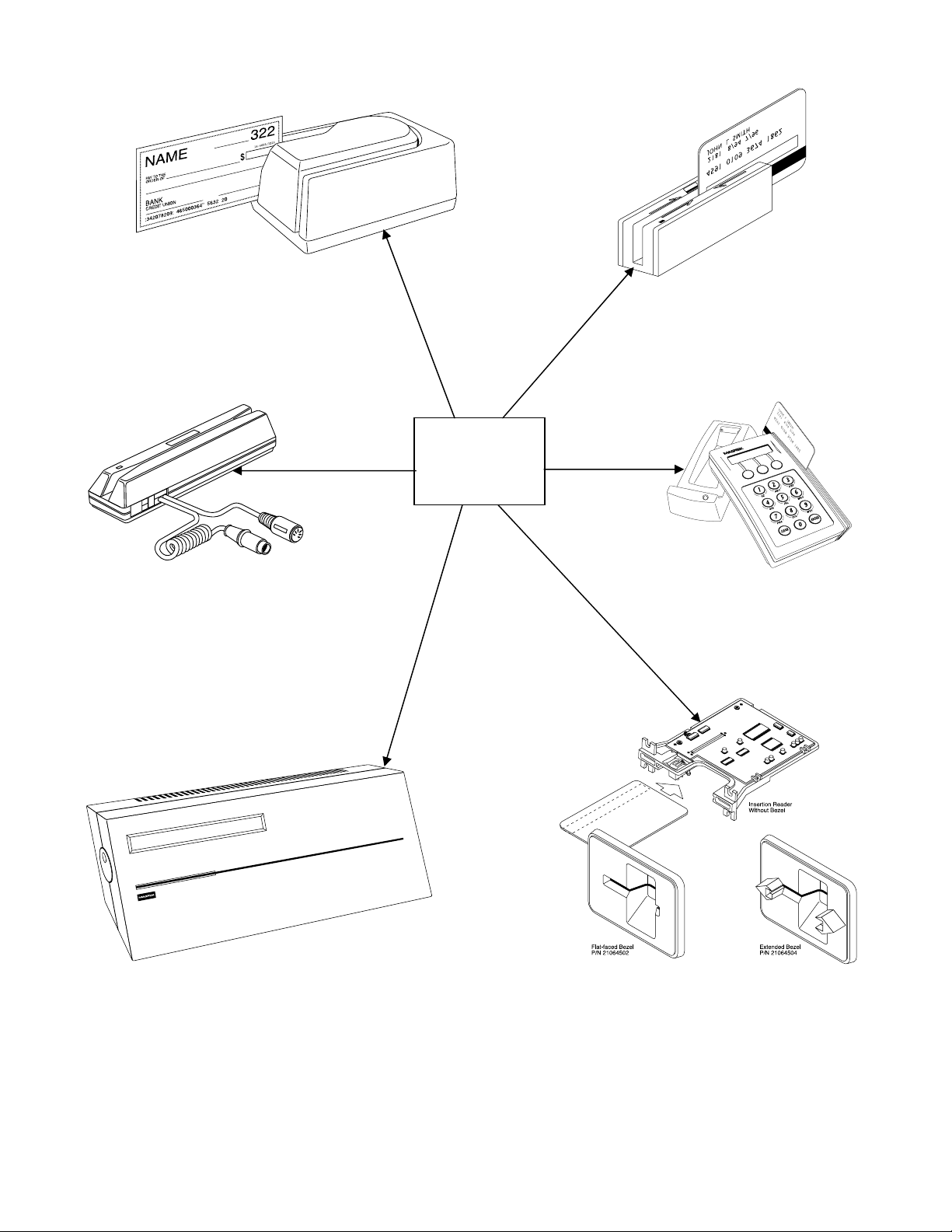
Figure 1-1. MagTek Devices and Device Drivers for Windows..................................................................viii
vii
Page 8
MTD
MagTek
Device Drivers
for Windows
Figure 1-1. MagTek Devices and Device Drivers for Windows
viii
Page 9

SECTION 1. OVERVIEW
The MagTek Device (MTD) Drivers for Windows is a collection of individual drivers that
support a number of MagTek products. These drivers provide a uniform application interface for
controlling a wide range of MagTek devices. The drivers, combined with a device control
language, solve many of the difficulties application developers face when attempting to control
hardware devices. The difficulties mount when faced with the task of developing an application
that supports an entire product line of devices.
Part Numbers for the MTD for all Windows platforms (95, 98, ME, NT, 2000, and XP) are as
follows:
Part Number Medium
30037385 CD
99510030 Internet*
*www.magtek.com
PROBLEMS WITH CONTROLLING DEVICES
The major problems with developing an application that supports an entire product line of
devices are as follows:
• Each MagTek device has a unique set of commands. The commands usually perform
similar functions on a particular class of devices but either differs in syntax or have small
variations in their functionality. An application would have to implement a custom
mechanism to control each device it supported–much like DOS applications had to do to
support various printers.
•
Most MagTek devices communicate via data streams, not packets. This means that an
application receives data from the device one character at a time; it only receives partial
command responses. It would be the application’s responsibility to collect the incoming
data and parse it into individual responses.
Responses from MagTek devices are inherently asynchronous. When an application
•
sends a command that requires a response, the response from the device arrives (or
worse, begins to arrive) long after the command is sent. The application would have to
either poll the device until all of the response is collected or implement a callback
mechanism to collect and receive it.
Most MagTek devices maintain a communication protocol of some kind. In addition to
•
this, the protocols differ between devices. For example, some devices frame responses
with STX and ETX control characters and others simply use a CR or require a checksum
in the frame. To deal with this, an application would have to recognize and implement all
of the various protocols for the devices it supports.
1
Page 10

MagTek Device Driver for Windows
• `MagTek devices are attached to the host in different ways. MagTek devices may be
attached to a serial port, parallel port, to another device or even to the keyboard port. All
these ports differ greatly in nature and would all have to be accessed by the application.
Additionally, meaningful communication with a device attached to the keyboard port
would be tricky at best. This is because the operating system does not provide a means to
send data to the keyboard port nor any mechanism to discriminate between the device
data and manual keystrokes.
BENEFITS OF A CONTROL LANGUAGE AND DRIVER
A device control language is defined to support most of the functionality of all MagTek devices.
As noted previously, most devices of a particular class have similar functionality. The control
language defines a common set of commands that perform these functions in the same way for
all MagTek devices, thus eliminating device-specific coding for most applications. If the need
arises to perform an operation on a device not covered by the common command set, a “raw”
send and receive command can be used to communicate directly with the device, effectively
eliminating any limitations on the amount of control you have over the device.
The control language is based on a simple property/command model. This model is familiar to
most developers who deal with properties and methods in development environments such as
Visual Basic or Delphi. You set up the device by getting and setting properties and operate it by
invoking commands.
The command set presents a synchronous interface to the application even though the device
operates asynchronously, greatly simplifying the effort in retrieving responses from a device.
The pattern is simple: send a command to the device and invoke a read command, which will not
complete until after the entire response is received from the device.
The control language is implemented by a driver, which completes the solution for the
application developer. The driver adds the following benefits:
• Gives easy access to the device. All MagTek devices are presented uniformly as a virtual
serial port, regardless of how they are actually attached to the host.
• Hides the communication protocol. Adding and stripping frames, performing
checksums, detecting and correcting communication errors, etc, are handled completely
by the driver. The application sees only the data that it is interested in and can be assured
that it is free from transport errors.
• Converts the incoming data stream into complete responses. The application receives
data from the device in easy to use packets. The entire response to a command is
received in a single operation.
• Makes it easier to upgrade to a new device. The driver shields you from differences in
the new device’s commands or interface. When upgrading the device, an application can
2
Page 11

Section 1. Overview
usually remain unchanged, even though the new device may be very different from the
old one.
The features of a driver that implement a device control language completely shield an
application developer from the complexities of device-specific functionality.
LANGUAGE OVERVIEW
The device control language is text based and designed to utilize the read and write file I/O
facilities of the underlying operating system. All commands, their responses and properties
consist of text strings that are written to or read from the driver using basic file I/O. The control
language is based on a property/command model that is similar to the notions of properties and
methods as accepted in environments such as Visual Basic or Delphi.
Properties
All properties are accessed in a uniform way: by using a get (/get prop) or a set(/set prop)
command. Properties are either read/write or read only. A set command with a read only
property will fail. All properties are identified by a string name and use strings for their
arguments. Properties defined by the control language fall into the following three groups:
•
Capability properties – These properties contain information about the capabilities of a
particular device and are generally read only. They allow an application to query a
device’s capabilities to determine if the device is suitable for a particular task. Included
in this category are c_cardwpin, c_check, c_pin, and c_magnetic (e. g., /get
c_check
Configuration properties – These properties configure a device for different modes of
•
operation or may alter the way some commands behave. Because of this, they are usually
readable and writable. They give an application the ability to set up a device for a particular
task that requires a specific, non-default mode of operation. Included in this category are
capitalize, dev_version, and port_name (e.g., /set capitalize 1).
•
Device-specific properties −These properties cover configuration requirements that are
not common among MagTek devices, even if the devices belong to the same class. An
application can determine if a particular set of device-specific properties is available by
first querying the device’s capabilities or version. Refer to Appendix D, Device Driver
Summaries, for a particular driver to see how these properties are affected with an
individual device.
Properties can be “action” properties. That is, the driver may execute an action on the device
when a property is set. For example, an application can enable or disable magnetic stripe tracks
by setting the trk_enable property. The driver responds by sending one or more commands to
the device to enable or disable the desired tracks.
).
3
Page 12

MagTek Device Driver for Windows
COMMANDS
Like properties, commands are identified by a string name and have string arguments. All
commands are terminated by line feed <LF> or a carriage return. To invoke a command, an
application simply writes it to the driver in the same manner as writing to a file or serial port. If
the command has a response defined for it, the application reads it from the driver using the same
I/O handle as in the write.
Four types of commands are defined by the device control language:
•
Non-interactive – These commands manipulate the device without requiring any
interaction with the user. The property commands get, set, reset, and ver are
examples of this type.
Interactive – These commands interact with the user. They do not necessarily require the
•
user to do anything but may only prompt the user to do something. display is an
example of such a command. Others, such as read or write, however, require user
interaction to complete. For example, the user must either swipe a card or cancel the
operation in order to complete a read command.
Device-specific – These commands give access to device-specific features. For example,
•
the load_key command is available for MagTek devices that use keys to encrypt data
before sending it to the host.
Raw – These are effectively escape commands. They allow the application to bypass the
•
driver to perform device-specific operations that are not included in the driver syntax and
not supported elsewhere. With these commands, an application has no limitations on the
amount of control it has over a device. The raw commands can be formatted exactly as
specified in the device documentation. The command bracketing will be inserted by the
driver if required (e.g., <stx> and <etx> will be inserted for certain devices). Three
commands are defined for this type:
data directly to the device, and
the first two.
A small set of interactive and non-interactive commands is all that is required for an application
to perform the most common tasks with these devices. Device-specific or raw commands should
rarely be needed.
rawsend and rawrecv, used to send and receive
rawxact, a transactional version that is a combination of
4
Page 13

Section 1. Overview
TYPICAL OPERATION
This section describes a typical pattern that an application developer may use to operate a device.
Although it is the most typical pattern, it is by no means the only viable one. Refer to Section 5,
Example Applications, to see how to use the drivers in various applications.
Open a device
Access to the device is obtained by opening the comxx: port that the device was installed as.
This is not the hardware port that the device may be attached to, but a virtual comxx: port
presented by the driver (e.g., COM5 or higher). A handle is returned by the open function and is
required for all subsequent interactions with the driver. When opened, the driver initializes itself
and, where required, the device.
Some drivers support automatic settings. In this mode, the driver first attempts to communicate
with the device at the previous setting or at the default setting if it is the first time. (The setting
for the initial attempt is grayed out in the manual settings fields.) If the driver for certain devices
(e.g., Mini MICR) does not receive a response, it will adjust the settings and try again. This
sequence continues until the device responds or until all possible settings have been attempted.
If the driver is set for the automatic mode, it may take considerably longer for the device driver
to detect an error. In particular, if the device is not connected to the specified port or if its power
is off, the device driver may take several seconds attempting all possible settings before it returns
an error. The application program should be tolerant of this delay. Not all of the devices support
the automatic mode of detection.
Query the device’s capabilities
The application can query the device to determine if it can perform the required task. The
capability properties (c_xxx) are provided for this purpose. For example, if an application
requires the ability to read checks, it can
get the c_check property to determine if the device
can read checks (e.g., /get c_check).
Prepare the device for work
The device is prepared for operation by setting one or more of the configuration properties. Its
mode of operation and other features are set up by these properties. Setting the
property to
1 to cause all data written to or read from a card’s magnetic strip to be capitalized is
capitalize
an example of this type of initialization. In some cases, modifying a property may cause the
driver to execute functions on the device.
Use the device
The device is now fully initialized ready for operation. Because most tasks with the device
require interaction with the user, the application operates the device using primarily the
interactive commands. A typical scenario is when, in response to some event, the user is
5
Page 14

MagTek Device Driver for Windows
prompted to swipe a card by using the display command, followed by a read command to
instruct the device to return the card data when swiped. All the facilities of the driver are utilized
during this stage of operation.
Close the device
When the application is finished with the device, it simply closes the port using the handle
obtained when it opened it. The driver shuts down the device if required.
METHODS OF ACCESSING THE DEVICE
This section describes how to use control language commands in a Visual Basic development
environment using the MSComm (Microsoft Communication) component.
Obtaining access to the device
If the MSComm (Microsoft Communication) ActiveX component is used to access the device,
set the CommPort property to the com port number of the device. Then, set the PortOpen
property to True to open it. The following example shows how:
‘set error handling
On Error Resume Next
‘open the port
Comm.CommPort = 5
Comm.PortOpen = True
If Err.Number <> 0 Then
<<process error>>
End If
on error goto 0
Note
After issuing an Open command, the computer may spend several
seconds attempting to communicate with the device. During this
time the computer will appear to be hung up.
If file I/O access is desired, you have the option of using either the device’s friendly name, such
\\.\micr+ (where \\.\ specifies to Windows that this is a device and not a file) or its port
as
name,
COM<5..15>. The friendly name is more intuitive and easier to remember than a port
number; however, the serial method gives the programmer better control of the device. The port
number can be found in the operating system’s device UI. For example, open Control
Panel/System/Device Manager/MagTek and select a specific driver. Under Properties, select the
Settings tab. This gives both the Friendly Name and the port name (COM<5-15>). It also
identifies the physical port that will be used to communicate with the device.
Open the device using either of the previous names. Use whatever facility is provided by your
development environment for opening files. For Visual Basic, do the following:
6
Page 15

Section 1. Overview
'set error handling
On Error Resume Next
‘open the port for binary access
Open “\\.\micr+” For Binary Access Read Write As #1
If Err.Number <> 0 Then
<<process error>>
End If
on error goto 0
Note
The friendly name of the device, as found in the operating system’s
device UI (Device Manager in Windows 98, for example), must be
prefixed with “\\.\” in order to open the device. If the previous
example did not have the prefix, it would create a file named
micr+ in the current directory–clearly not the desired result.
Interacting with the device
An application interacts with the device by sending commands to the device and reading its
responses. Commands are sent by writing to the opened port and responses from the device or
property requests are retrieved by reading from the port.
To interact with the device using the MSComm component, invoke a command by assigning it to
MSComm’s Output property. The response is received by MSComm’s OnComm event handler
as a comEvReceive event or by directly polling the port. The entire response to a command or
property request is received as a single event.
'submit echo command
Comm.Output = "/echo Hello" + Chr$(10)
Private Sub Comm_OnComm()
‘return if not a receive event
If Comm.CommEvent = comEvReceive Then
‘process received data
a$ = Comm.Input ‘get echo data
Else
<<process non-read event>>
End If
End Sub
If using file I/O access, interaction with the device is indistinguishable from writing to or reading
from a file.
7
Page 16

MagTek Device Driver for Windows
‘set up error handling
On Error Resume Next
‘submit echo command
Put #1, , "/echo Hello" + Chr$(10)
‘declare an input buffer
a$ = String(2000, Chr$(0))
‘read echo response from device
Get #1, , a$
If Err.Number <> 0 Then
<<process error>>
End If
Note
File I/O interaction with the device is synchronous; the read operation
will block until a response is received from the device or is returned by
the driver (as in a property request). This means that a read command
cannot be canceled because the computer will not accept any new
commands while one is pending. The only exception to this is when the
development environment provides access to the Win32 API, giving the
application the ability to use overlapped file I/O.
Releasing access to the device
Releasing access to the device is very simple. If using MSComm, close the device by setting its
PortOpen property to False:
‘close the port
mscomm1.PortOpen = FALSE
If opened as a file, close it as in the following:
‘close the port
Close #1
ERRORS AND ERROR PROCESSING
A command’s execution status is returned to an application in the command’s response, if it has
one. The status value is a two digit numeric field located at positions 23 and 24 of the response
(refer to Appendix C. Status Codes for a description of all error conditions) .
Errors are processed differently for property manipulation. If an error occurs while getting a
property, the response will be returned with an empty property value. No status is returned when
setting a property because the
set command has no response defined for it.
If a command returns a non-zero status, indicating an error, an application can typically respond
in the following manner:
8
Page 17

Section 1. Overview
1. It can prompt the user to repeat the action and re-submit the command. This is typical if
the status does not indicate a failure, per se, but that the device may not be ready yet or
first needs some other interaction by the user.
2. It can reset the device and prompt the user to repeat the action. Typically, this action is
necessary if the device’s state or configuration has been corrupted, but is otherwise
functioning correctly.
3. Finally, the application can refuse to continue operation of the device. An application
should do this only if the returned status indicates that the device is malfunctioning.
HANDLING SPECIAL COMMANDS
Generic Devices
Some devices such as the IntelliPIN support a set of commands that are not standard and/or do
not follow the usual protocol. The Generic Driver can be used to support these commands. It
does not know how to communicate with any device and does not support any protocol. The
Generic Driver allows the application to send any string to a device. When the Generic Driver is
used, the application must form the command, insert packet characters, and compute a check
character where required. The Generic Driver only supports the “raw” commands.
The Generic Driver can be used whenever a deviation from the standard protocol is required or
when no protocol exists at all. However, the Generic Driver, unlike all of the other drivers, does
not support any properties. It is only available to support those cases that cannot be handled with
the standard drivers.
IntelliPIN Driver
With release MTD 1.12, the IntelliPIN driver has been updated to support the special set of
commands that require <si> and <so> instead of the usual <stx> and <etx> characters. These
special commands that support the multi-master keys (e.g., 02, 04, 08, etc.) are not supported
with the standard IntelliPIN commands. However, if these commands are used in the
/rawsend or /rawxmit commands, the <si> and <so> will automatically be inserted.
MICR Format Numbers
In order to retrieve the built-in check properties (chk_***), the driver automatically configures
the MICR units to format number 6500. However, there are some cases, especially outside the
United States, where the check information is not consistent with format number 6500. In these
cases, the installer has the option of modifying the format number string in the OEMSETUP.INF
file.
9
Page 18

MagTek Device Driver for Windows
The format number can be changed to another value (e.g., 7700 to allow use of a flex format) by
editing the field following the format number entry (%CheckFormatCodeName%) in the
OEMSETUP.INF file. This must be changed in three places depending on which drivers are to
be used (MICR+, MiniMICR RS232, and MiniMICR Wedge). By defining a flex format that
would duplicate the 6500 output format, the driver will still be able to parse the check data and
present the individual properties (e.g., chk_account, chk_amount, chk_number, and chk_transit).
If a suitable format cannot be developed to present the individual properties, the driver will still
be able to present the check data (chk_data) as received from the MICR reader. If the existing
format number in the MICR device is suitable, set the %CheckFormatCodeName% entry to null
(i.e., “”), so it will not be modified by the Driver.
Refer to the appropriate MICR Technical Reference Manual for more information about the use
of format numbers and available MICR fields.
FILE PROPERTIES
When updating the MagTek Device Drivers, discussing performance characteristics, or reporting
errors, it will be important to identify the part number and version of the associated file(s). In
order to determine which version is installed, use Windows Explorer and go to the
\Windows\System directory. Right click on the associated “VXD” or “SYS” driver file (see
Appendix A. Installation and Setup) and select Properties. Click on the Version tab. Note the
File Version, Part Number, and Description.
INSTALLATION
The drivers are installed by means of an InstallShield application. All Windows platforms (95,
98, ME, NT, 2000, and XP) are supported. Refer to "Appendix A. Installation and Setup" for a
full description of the installation procedure.
10
Page 19

SECTION 2. PROPERTIES
This section lists the properties that are used in the MagTek Drivers. Properties can be
interrogated by issuing a
Commands for complete description and examples of all commands.
The
c_xxx properties are set by the driver and reflect the device’s capabilities. However, the
c_xxx properties do not indicate the configuration of the device. For example, a device may be
capable of reading all three magnetic tracks but be configured to only read two tracks or a MICR
reader, while often configured with a magnetic stripe reader, may not have an MSR installed.
Unless otherwise noted, 1 means the capability is available, 0 or null (i.e., the value is not
present) means that the capability is not available.
In this table, the Access information indicates whether the property can be modified (Read/Write
–R/W) or merely accessed (Read Only–R).
Property Access Description
account_no
amount
applied_fmt
c_card_stat
c_cardwpin
c_check
c_events
c_keypress
c_keystring
c_magnetic
c_mechanics
c_pin
c_smart
c_tracks
get command and modified with a set command. Refer to Section 3.
R/W Cardholder account number, including check digit. It is set by the
application to be used in PIN encryption commands (IntelliPIN).
R/W Transaction amount in cents, without punctuation (IntelliPIN).
R Indicates which format template was used to parse the magnetics
data. If no template or rule is applied, this property returns a null.
R
1 indicates that the driver supports retrieval of card sensor status
(e.g., PPINSERT)
R
1 if the device supports reading of a card and a PIN in response to
a single command (e.g., IntelliPIN).
R
R
1 if the device can read checks (e.g., MICR devices).
1 indicates that the driver supports unsolicited event notification
(e.g., PPINSERT).
R
R
1 if the device supports retrieval of a key press (e.g., IntelliPIN).
1 if the device supports retrieval of a sequence of key presses (e.g.,
IntelliPIN).
R
1 if the device can read magnetic cards.
R This value indicates how the card reader’s mechanism operates:
0 – manually operated device or no card reader
1 – device is mechanized and supports “eject”
2 – device is mechanized and supports “eject” and “confiscate”
R
R
1 if the device supports reading of PINs (e.g., IntelliPIN).
1 if the device supports smart cards.
R A three-character string, representing the tracks supported by the
device. The left-most position indicates track 1. Thus 110
indicates that the device can access tracks 1 and 2 but not track 3.
trk_enable to determine which tracks are enabled.
See
11
Page 20

MagTek Device Driver for Windows
Property Access Description
c_write
R
1 if the device can encode a magnetic card in either LoCo or HiCo;
2 if the device can encode a magnetic card in only the setting
indicated in wr_coer
c_wr_secure
R
0 if the device does not support secure mode;
1 if the device can switch between secure and non-secure mode
(see wr_secure);
2 if the device only operates in the secure mode.
capitalize
card_stat
chk_account
chk_amount
chk_bankid
chk_data
chk_format
R/W
Set this to 0 to prevent the driver from capitalizing the data for the
read and write commands. The default value for this property is
1 (enable capitalization).
R Current card sensor status:
0 = not blocked, 1 = blocked (PPINSERT).
R Check account number from check (MICR).
R Check amount from check (MICR).
R Bank ID number from the transit field (MICR).
R Output data string as received from MICR reader (MICR).
R/W
Indicates the format of the check data. Set to 6500 by default. If
this property is modified by the application, the chk_xx properties
(except chk_data and chk_status) will be set to null. (MICR)
chk_mod10
chk_number
chk_routing
chk_status
chk_transit
cmd_pending
dblpinentry
dev_status
R Mod10 check digit from the transit field (MICR).
R Check number (MICR).
R Routing number from the transit field (MICR).
R 2-digit status code from the check just read (MICR).
R Transit number from check (MICR).
R Command pending–indicates which command, if any, is pending.
If none is pending, the second argument will be null:
/get cmd_pending<LF>
R/W
R
Set to 1 to enable double PIN entry such as when requesting a new
PIN; set to
0 when verifying a customer’s PIN (IntelliPIN).
Device status. 0 means device is connected and operational. Any
other value indicates a device-specific error. If the device fails to
respond, a null value is reported:
/get dev_status<LF>
dev_version
R Device version string. This value is read directly from the device,
if the device supports a version string. <CR> characters in the
string read from the device will be replaced with /. This property
will be useful in reporting operational problems to MagTek.
enable_cmc7
R/W
Set this property to
1 to enable CMC-7 characters decoding, 0 to
disable it. This is used for international checks; see MICR manual
for more information. (MICR)
12
Page 21

Section 2. Properties
Property Access Description
enc_key
enc_key_sn
R/W Encryption key to use for the next encryption process (IntelliPIN):
Set Get Key
M 4 Master key
S 5 Session key
0-3 0-3 Lower working keys
A-J A-J Upper working keys
WA-WZ A-Z Working keys A-Z
Wa-Wz a-z Working keys a-z
R/W Serial number of encryption key. Used to specify key serial
number for activating/deactivating PIN encryption in MSK mode
and to return the key serial number in DUKPT mode. The key
serial number is specified in clear text (IntelliPIN).
enc_mode
entry_echo
R/W
Current encryption mode – msk or dukpt (IntelliPIN).
R/W Specifies how to display the characters when entered from the
keypad on the LCD screen (IntelliPIN):
• + (plus) to display as entered
• - (minus) to suppress display
entry_len
entry_tout
events_on
invalcmdrsp
key_parity
lasterr
max_pin_len
• $ to display as amount
The value of this property affects the operation of the read
key_string
command. By default this property is empty.
R/W Maximum number of characters (1-32) to be collected with the
read key_string command. An empty value (default) for this
property converts to a length of 1. (IntelliPIN)
R/W Entry timeout: number of seconds (15-255) to wait for keypad
input. (IntelliPIN)
R/W
Set to 1 to enable unsolicited event notifications. The default is 0.
(PPINSERT)
R/W
Invalid command response: set to 1 to enable responses to invalid
commands (useful during program development). This is set to
(disabled) by default.
R/W
Set to
1 to enable parity check on encryption keys. (IntelliPIN)
R Status from the last command sent to the driver. A successfully
executed command will reset this value to 0. This property is
useful for checking the operation of the set commands. After
each
set, the response to get lasterr should be 0.
R/W Maximum PIN length (IntelliPIN):
• 1 – 16 for ibm format (IBM 3624)
0
• 4 – 12 for ansi format (ANSI 9.8)
13
Page 22

MagTek Device Driver for Windows
Property Access Description
msg1 - msg4
R/W Messages to show on LCD screen with various commands.
msg1 – used by the read and display commands
msg2 – used by the display and read Card_w_pin
commands
msg3 – used by the read Card_w_pin command
msg4 – used by the key_press and key_string operations
To specify leading spaces, use \x20. See the display command
for more information. (IntelliPIN)
offline_enc
R/W
Set to 1 to enable encode capability in standalone mode with
keyboard; 0 prevents standalone encoding (MT-95).
oper_tout
pin_blk_fmt
pinfilldig
port_name
R/W Operational timeout in seconds (15-255). (IntelliPIN)
R/W PIN block format (IntelliPIN):
ansi (ANSI 9.8) or ibm (IBM 3624)
R/W
PIN fill digit (0..9, A..F) when pin_blk_fmt is ibm (IntelliPIN)
R Indicates the virtual port number (e.g., COM6) derived from the
friendly port name.
pwroffdelay
s_down_tout
track1ss
track2ss
track2ss
trivpinchk
trk_enable
R/W Power off time delay in minutes (5-255). (IntelliPIN)
R/W
R
R
R
R/W
Shutdown timeout in hours (1-31). Set to 0 to disable. (IntelliPIN)
Indicates Start Sentinel on Track 1 as received from the device.
Indicates Start Sentinel on Track 2 as received from the device.
Indicates Start Sentinel on Track 3 as received from the device.
Set to 1 for trivial PIN checki.e., don’t allow 1234. (IntelliPIN)
R/W Enable reading and writing of individual tracks. The value of this
property is a string of three characters, with 0 representing
disabled tracks and 1 representing enabled tracks, e.g., 110 enables
tracks 1 and 2 and disables track 3.
trk1data
trk2data
trk3data
visa_mac1
visa_mac2
visa_mac3
wr_coer
wr_secure
R Data from track 1 excluding start sentinel and end sentinel.
R Data from track 2 excluding start sentinel and end sentinel.
R Data from track 3 excluding start sentinel and end sentinel.
R Message authentication codes returned by device after PIN is
collected (DUKPT mode only). (IntelliPIN)
R/W Encode Coercivity Mode (MT-95). Specifies the energy level used
to encode the magnetic stripe:
0 = automatic selection
1 = LoCo only mode
2 = HiCo only mode
R/W
0 indicates the card can be removed between a read and write
operation. Set this to
1 to turn on secure online encode mode (MT-
95).
xact_type
R/W
Transaction type – d = debit, c = credit (IntelliPIN).
Properties like account_no and those properties created by the data parsing templates (see
Section 4) that are affected by a card transaction will be modified only when a card is read
without errors.
14
Page 23

SECTION 3. COMMANDS
This section describes all of the commands that can be used with the MagTek Windows Device
Drivers. Some commands require parameters to indicate to the driver exactly what function is to
be performed. While there are a few device-specific commands, most commands can be used
with any device.
DATA FORMAT
All commands sent to the driver and all responses received are strings of printable ASCII
characters delimited by <LF>. The driver will also accept <CR> as a delimiter. All command
and response strings begin with the character /. If a command has arguments, they should be
separated with one or more white spaces. The driver accepts space
space characters.
Note
A command delimiter sent immediately after the previous
command delimiter is interpreted as an empty command and is
ignored by the driver.
RESPONSES
All responses to the transaction commands are formatted with fixed fields, to allow them to be
parsed either by scanning for white spaces or by using constant offsets into the response string.
In the descriptions of the commands found later in this section, the arguments sent with the
responses are shown in their respective locations but may not indicate the exact number of
spaces. The actual responses are sent in a fixed-field format, as shown in the following table:
Field Offset Size Comment
command name 0
(0-11)
arg1 12
(12-23)
arg2 24
(24-??)
12 This field identifies the command that produced this
response, e.g., /get is followed by 8 spaces to fill
the 12 locations.
12 Fixed-size argument – value depends on the
command sent. A property name is left justified in
the field and begins in location 12. Status
information is right justified in the field (with a
trailing space) so the SS value will always be located
at positions 21 and 22.
var Variable size argument – used for responses with
variable-size data, like /get prop or read status
data.
<SP> and <TAB> as white
15
Page 24

MagTek Device Drivers for Windows
Examples:
000000000011111111112222222222
012345678901234567890123456789
/read -00082
/get trk_enable 110
NOTATION CONVENTIONS
The following conventions are used in the tables that follow.
Fixed Size (Bold)
Used to represent literals (symbols, exactly as sent or received
from driver)
Italic
Used to represent placeholders (variable fields)
[] Expression parts in brackets are optional. The brackets are never
a part of the syntax
<LF>
ASCII control character. The only ASCII control characters used
are <LF> (0x0A) and <CR> (0x0D).
(a|b) Means that the expression can be either a or b, e.g., X(1|2) means
either X1 or X2. The parentheses and the | are never part of the
syntax.
COMMAND DESCRIPTIONS
The following list of commands includes function, syntax, errors, remarks, and examples as
applicable.
cancel
Function
Syntax
Cancel a command.
/cancel [cmd]
The optional cmd can be any of the transaction commands such as:
/cancel rawrecv
/cancel rawxact
/cancel read
/cancel write
If cmd is omitted, any pending commands will be canceled.
Errors
If the specified command is not active, the command is ignored and there is no
response.
Remarks
Example
The command being canceled will send a response immediately.
If a read command has been issued but the operation is to be aborted:
Command
Response
/cancel read<LF>
/read -00082<LF>
16
Page 25

Section 3. Commands
display
Function
Syntax
Show a single message or two alternating messages on the device’s display.
/display [x]
The optional argument x indicates the message to be displayed.
Errors
Remarks
none
If the optional argument x is provided, this command displays it as a single message.
If x is @, the driver sends a command to the device to display the idle message 00
(“Welcome”). If x is omitted, the command uses the values of the msg1 and msg2
properties for the message texts. If msg2 is empty, this command displays the text in
msg1; otherwise, it displays the texts in msg1 and msg2 as alternating messages. The
message texts are displayed unmodified, except for any ‘\’ characters, which are
used as escape characters:
\r is converted to 0x0D (shown as <CR> in this document)
\n is converted to 0x0A (shown as <LF> in this document), e.g., to be used as
line separator for LCD screens that can display multiple lines
\\ is converted to \
echo
Function
Syntax
Errors
Remarks
Example
\xhh is converted to a character with ASCII value hh (always two hex digits).
Not all ASCII values can be displayed.
Leading and trailing spaces are removed from the message texts in the x
argument and the msg1 and msg2 properties. \x20 may be used for adding
leading spaces.
To center the message “Thank You” on the IntelliPIN LCD:
Command
Response
/display \x20\x20\x20Thank You
none
Echo data−driver test command.
/echo string
string is limited to 11 characters (the width of the ‘arg1’ field in the response
format) without any embedded spaces.
none
The driver responds by echoing the command back. If the command specifies a
string that is longer than 11 characters or if a space appears, the response will be
truncated. There is no translation for escape (\x00) commands. This command
cannot be cancelled with
/cancel.
If you wish to ensure that the driver is properly installed, request it to echo a string:
Command
Response
/echo Testing<LF>
/echo Testing<LF>
17
Page 26

MagTek Device Drivers for Windows
event
Function
Syntax
Errors
Remarks
Response to an unsolicited event notification.
none
none
This response can occur when an unsolicited event, such as card inserted, occurs.
The format of the response is: /event n data
n is a numeric event code:
1 – medium has been inserted into the reader
2 – medium has been removed from the reader
data specifies the type of medium that was inserted/removed:
M – magnetic
Events are sent to the application only if the c_events property is 1 (driver supports
events) and the events_on property is set to 1 by the application.
If a card has already been inserted when the driver is opened, there will not be any
notification when
/get card_stat be issued immediately after opening the driver to see if a card
events_on is enabled. Consequently, it is recommended that
is blocking the sensor.
Example
If you wish to be notified when a card has been inserted into the PPINSERT:
Command
Response
/set events_on 1<LF>
/event 1 M<LF>
When a card is inserted into the slot.
get
Function
Syntax
Get a property.
/get prop
prop is one of the valid properties shown in Section 2 or any of those from data
parsing.
Errors
Remarks
/get abc<LF>
Since abc does not exist.
The driver sends a response in the format: /get prop val.
If the requested property does not exist, the val field will be empty, i.e., <LF> follows
the prop field. If the command was cancelled, both the prop and val fields will be
empty. In some cases, this command will interrogate the device to determine the
property setting. Some properties cannot be interrogated if a command (such as read)
is pending. The value will be null in this case.
Example
If you wish to find out which tracks are enabled, request the trk_enable property:
Command
Response
/get trk_enable<LF>
/get trk_enable 110<LF>
Indicating track 1 & 2 are enabled, track 3 is disabled.
18
Page 27

Section 3. Commands
load_key
Function
Syntax
Load an encryption key into the device.
/load_key n key
n can be one of the following values:
M – master key (key is in clear text)
S – session key (key is encrypted under Master Key)
0 ... 3 – lower working keys (key is encrypted under Session Key)
A ... J – upper working keys (key is encrypted under Session Key)
key is the 16- or 32-character value of the key to be loaded.
Errors
/load_key 30<LF>
If the n field is invalid, key is the wrong length, or the device sends an error
(e.g., there is a key parity error).
/load_key 45<LF>
If the required key is not loaded.
Remarks
This command is used to load a key into the device. With all but the master key, the
selected key is encrypted under another key so the application must know the
encrypted value of the key. The response to this command is: /load_key SS
SS is a two digit status code; 00 – success, 30 – invalid, 45 – rejected, etc.
Example
To load the session key encrypted under the master key:
Command
Response
/load_key S 99E1E835662DEA94<LF>
/load_key 00<LF>
19
Page 28

MagTek Device Drivers for Windows
rawrecv
Function
Syntax
Errors
Receive data from the device.
/rawrecv
/rawrecv 45<LF>
If a command is already pending.
/rawrecv 82<LF>
If the command was canceled by the user (e.g., with CLEAR key)
Remarks
This command overrides the default processing of the next message that comes from
the device and returns it to the application as a rawrecv response. Only one
message from the device will be processed in this manner, after that the driver
switches to normal operation. The response to this command is in the following
format: /rawrecv status x
status is a 2-digit decimal value (refer to Appendix C. Status Codes for a
complete description of the status values)
x is the data received from the device with the following characters replaced:
• <CR> is replaced by \r
• <LF> is replaced by \n
• \ is replaced by \\
Example
• any other non-printable characters are replaced by \xhh, where hh is the
two digit hex code of the character.
If a /rawsend command is sent that will cause the device to send back a response,
the application should either submit a /rawrecv command before sending the data
with /rawsend, or (better) use the /rawxact command.
Note
In some cases, the framing characters in the response
are extracted by the driver and are not presented to
the application.
To receive card data when the IntelliPIN is operating in the VeriFone mode:
Command
Response
/rawrecv<LF>
/rawrecv 00 ;12345?<LF>
20
Page 29

Section 3. Commands
rawsend
Function
Syntax
Send arbitrary data to the device.
/rawsend x
x is an arbitrary string which is transmitted directly to the device. The string x is passed
as-is to the device, except for ‘\’ which is used as an ‘escape’ character:
• \r is converted to <CR>
• \n is converted to <LF>
• \\ is converted to \
• \xhh is converted to a character with ASCII value hh (always two hex digits),
e.g., \x20 is converted to a space.
Errors
Remarks
none
This command as with the other raw commands supports any features that have not been
implemented in the standard set of commands. Note: the driver inserts appropriate framing
characters, e.g., <stx> and <etx> or <si> and <so> for certain IntelliPIN commands.
Example
rawxact
Function
Syntax
Errors
Remarks
To change the default message 00 to show “Welcome to Our Bank” on two lines of the
IntelliPIN:
Command
Response
/rawsend 5100Welcome to\x1COur Bank<LF>
none
Note: When using C++, include an extra slash to include the “/r”: “//rawsend…”
Execute a send/receive transaction with the device in raw mode.
/rawxact x
x is an arbitrary string which is transmitted directly to the device. The string x is passed
as-is to the device, except for ‘\’ which is used as an ‘escape’ character:
• \r is converted to <CR>
• \n is converted to <LF>
• \\ is converted to \
• \xhh is converted to a character with ASCII value hh (always two hex digits),
e.g., \x20 is converted to a space.
/rawxact 45<LF>
If a command is already pending.
/rawxact 82<LF>
If the command was canceled by the user (e.g., with CLEAR key)
This command is a combination of /rawsend and /rawrecv. It sends the supplied data to the
device, overrides the default processing of the next message that comes from the device and
returns it to the application as a /rawxact response. After the response is returned (or
canceled), the driver switches to normal operation. The syntax for this command is identical
to the syntax of the /rawsend command; the syntax of the response is identical to the
/rawrecv response.
Example
To load a master key of 23AB4589EF6701CD into the IntelliPIN:
Command
Response
/rawxact 9423AB4589EF6701CD<LF>
/rawxact 00 940<LF>
21
Page 30

MagTek Device Drivers for Windows
read
Function
Syntax
Read data from the device.
/read [[x] y]
The optional argument x specifies the data source; if x is missing, a card will be
read. Refer to the Read Argument table below for a description data sources.
The optional argument y is used to specify a message to be displayed on the
LCD screen, if supported, before carrying out the command. If y is omitted
and the device supports a display, the text in the msg1 property is shown. In
order to use y, the x argument must be present. See the display command
for the description of the message format for y.
Errors
/read -00045<LF>
If a command is already pending or the enc_key is not defined for read pin.
/read -00082<LF>
If the command was canceled by the application (82) or by the user (83) (e.g.,
with CLEAR key).
Remarks
The response to this command has the following format: /read status data
The status field is a 6-character string aligned to the right in the arg1 field. It is
formatted as follows: TX1X2X3SS
T defines the type of data that was read:
C = a check was read
M = a magnetic card was read
P = a PIN was read
K = a key press or string was read
- = indeterminate: no data was received from the device. Returned on errors
not specific to the data type, such as command canceled (SS=82).
Xi define a media-specific status. For checks, this is the decimal representation of
the check read status, as defined in the MICR specification. For magnetic cards,
XXX indicates the read status for each of the three magnetic tracks (see card in
the Read Arguments table below for a description of the status). For PIN data
this status is always 000; for keypress and string data, XXX is the data length in
characters.
SS is a two-digit status code. 00 indicates a good read (but some tracks may be
bad); any other status code indicates an error. These error codes indicate an error
in the communication between the driver and the device or driver’s internal
errors. Read errors are reported in the Xi fields and do not cause the SS field to
be set to a non-zero value. See Appendix C. Status Codes.
write command below.
Example
The data format is described in the
To request an amount to be entered by the customer on the IntelliPIN:
Command
Response
/set entry_len 6<LF>
/read key_string Enter the amount<LF>
/read K00300 123<LF>
Example
22
To read a card (from any device):
Command
Response
/read card<LF>
/read M10900 ;12345?<LF>
track 1 error, track 2 good, track 3 blank
Page 31

Section 3. Commands
Read Arguments
The optional argument x used in the read command specifies the type of data to read and y
specifies the text to be displayed. The following table describes the recognized x arguments for
the read command:
Read
Description
Argument
any
card
Read any type of data.
This option is equivalent to read without any arguments.
Read magnetic stripe card. Display message (msg 1) if defined.
When the user swipes a card, the response will be in the following format:
/read MX
1X2X3
SS data
XI define the track read status for each of the three tracks, as follows:
0 = good track
1 = bad track
9 = no track data.
SS is a two-digit status code; it is not affected by errors reported in the
Xi field:
00 – successful read
82 – canceled, etc.
data is the card data for all successfully read tracks.
card_w_pin
Read magnetic stripe card and collect PIN from cardholder. Display
messages if defined.
This command is similar to the read card command except that after the
card is swiped, the device collects and stores the cardholder’s PIN. The
PIN can be collected later by issuing the read pin command.
Before issuing this command, the following properties may be set:
msg1, msg2, msg3 – messages to be displayed while waiting for card
swipe and PIN entry (a default message will be used if these properties
contain empty strings).
The response to this command is identical to the read card response; if
successful, it returns the track data from the magnetic card. If the response
status SS is 00, the read pin command can be used to collect the PIN.
check
Read check data.
When the user reads a check, the response will be in the following format:
/read CX
1X2X3
SS data
XXX is the decimal representation of the check read status, as defined in
the MICR specification, e.g.,
004 indicates a bad character in the
check number field.
SS is a two-digit status code: 00 – successful read, 82 – canceled, etc.
This status is not affected by errors reported in the XXX field.
data is the check data, which is also available in
chk_data. The data
format depends on the setting of the chk_format property.
23
Page 32

MagTek Device Drivers for Windows
Read
Description
Argument
chk_or_card
key_press
Read magnetic stripe card or check data. When a card or check is swiped
through the device, the driver sends the respective response.
Display a message (msg4) on the LCD screen, if available, and wait for a
key on the keypad to be pressed. The device will wait for
entry_tout
seconds for the key press (by default 0 for no timeout). The response to
this command is:
/read KXXXSS K
XXX is the number of keys collected. Always 001 on successful read,
000 if failed.
SS is a two-digit status code: 00 – successful read, 81 – timeout, etc.
K is the ASCII representation of the pressed key (if SS is 00).
key_string
Display a message (msg4) on the LCD screen, if available, and collect a
string of key presses (digits) from the device. The following properties
affect this command:
• entry_tout – number of seconds to wait for input (by default 0 for
no timeout)
• entry_echo – how to display the characters entered from the
keypad on the LCD screen: “0” (zero) to display, “+” to echo, “-”
- (minus) to suppress display, “$” to display as amount. Empty by
Default (must be set prior to use).
• entry_len – maximum number of characters to be collected.
An empty value for this property is interpreted as a length of 1 by the
device (default).
The response to this command is in the following format:
/read KXXXSS data
XXX is the data length in characters
SS is a two digit status code:
00 – successful read
30 – entry – echo not set
81 – timeout
83 – input aborted, etc.
data is the string collected from the device.
24
Page 33

Section 3. Commands
Read
Argument
pin
Description
Collect PIN from cardholder and read PIN data from the device.
The following properties may be set before issuing this command:
• account_no – cardholder account number, including check digit,
if required
• amount – transaction amount in cents, without punctuation, if
required
• enc_key – (MSK mode only) encryption key to use: M for master,
S for session, 0-3 for lower working keys, A-J for upper working keys.
• xact_type – (DUKPT mode only) transaction type: D for debit, C for
credit
The response will be: /read P000SS pin_block
SS is a two-digit status code:
00 – successful read
45 – enc_key is not defined
83 – aborted, etc.
pin_block is the encrypted PIN block as returned by the device.
Upon successful read, the following properties will be set:
• Visa_mac1, visa_mac2, visa_mac3 – message authentication
codes (DUKPT mode only)
• enc_key_sn – serial number of encryption key (DUKPT mode only)
25
Page 34

MagTek Device Drivers for Windows
reset
Function
Syntax
Errors
Remarks
Reset the device.
/reset
none
Clear any pending operations and reset the device to initial state. This does not
affect any of the properties.
Example
To return a device to its initial state:
Command
Response
/reset<LF>
none
set
Function
Syntax
Set a property.
/set prop val
prop is one of the valid properties (R/W) shown in Section 2. Properties
val represents the value of that property.
Errors
Remarks
none
This command is used to define each of the properties that are required prior to
sending a command.
Example
To load the key serial number in the IntelliPIN:
Command
Response
/set enc_key_sn 0123456789012345<LF>
none
ver
Function
Syntax
Errors
Remarks
Example
Read driver version.
/ver
none
The response to this command is sent in the following format: /ver num text
num is the driver’s part number
text is a free format version string. It may contain a tagged-format data enclosed
in parentheses, as shown in this example
This is not the version of the device.
To determine the version of the currently active driver:
Command
Response
/ver<LF>
/ver 30037395 Mag-Tek Device Driver
(Version=1.04 Model=IntelliPIN)<LF>
26
Page 35

Section 3. Commands
write
Function
Syntax
Errors
Data encode command.
/write data
/write 94<LF>
Encode is not supported on this device.
/write 34<LF>
The data field was in the incorrect format.
/write 82<LF>
The write command was canceled.
/write 45<LF>
Device in wrong mode (e.g., if /read already issued)
/write 60<LF>
Error during write operation (e.g., on MT-95)
Remarks
The data field is in the following format:
[%an-data?][;n-data?|@a-data?][(+n-data?|#an-data?|!an-data?|&an-data)]
an-data is alphanumeric data (ASCII characters ‘ ‘ to ‘_’ (0x20 to 0x7f))
n-data is numeric data (ASCII characters ‘0’ to ‘?’ (0x30 to 0x3f))
The data should not contain the end sentinel character (?).
If the application sends data for an alphanumeric track that contains lowercase
characters (ASCII values beyond 0x60), they will be capitalized if capitalize =
1. To disable this and send the data as-is to the device, set the capitalize property
to 0. The three sub-sections of the data string represent the three tracks on the
magnetic card. The data for each track begins with a start sentinel character, which
defines both the track number and the data format for the track:
% identifies track 1 (7-bit alphanumeric)
; identifies track 2 (5-bit numeric)
@
+
identifies track 2 (7-bit alphanumeric)
identifies track 3 (5-bit numeric)
! identifies track 3 (CA Driver License)
# identifies track 3 (alphanumeric, AAMVA)
& identifies track 3 (7-bit alphanumeric)
Note that any or all of the data may be missing, but the order of the data for the
tracks must always be in order (1, 2, 3). A missing track is interpreted as “don’t
write” for the data encode command – that track will not be overwritten by the
encode operation.
The response sent for this command is:
status is
00 if the encode succeeded and non-zero if it failed.
/write status.
See the definitions of the status values in Appendix C. Status Codes.
Example
Encode tracks 1 and 2:
Command
Response
/write %B12345^TEST^0000?;12345?<LF>
/write 00<LF>
27
Page 36

MagTek Device Drivers for Windows
28
Page 37

SECTION 4. MAGNETIC CARD DATA PARSING
This section describes the flexible data parsing language to be used by the MagTek device
drivers to parse specific fields from magnetic card data and expose those fields as properties
which may be retrieved by an application using the /get command. The data parsing language is
flexible in that it can define both standard and custom formats to be parsed by the driver.
GOALS
For most MagTek devices, the MTD drivers completely hide the device-specific commands and
peculiarities, thereby allowing applications to use the same command set and logic for all
devices.
Up to this point, the above mentioned encapsulation has not been applied to the data returned by
the device when a magnetic card is swiped. It has been left to the application to interpret the
card data. This can become troublesome because the track formats and or/data contained on each
track vary depending on the type of card (e.g., ATM or Drivers License).
The goals for the flexible data parsing are:
• easy to specify formats
• allow parsing of standard formats
• allow extending formats with custom fields
• allow detection of format and applying different parsing
• allow for missing tracks and missing fields by setting the corresponding property to empty
• allow presets to be loaded from the registry
• to expose parsed fields to applications via the /get command
• allow MagTek or system integrators to define formats in the driver installation file
(OEMSETUP.INF).
ASSUMPTIONS
• The driver validates the format template and rules for syntax, but it cannot validate the
format string for correctness in relation to parsing the fields of data. For example, if the
format string specifies that a field has a fixed size of 3 and it actually has a fixed size of 4,
the driver will not detect this.
• There is no backward parsing (i.e., field identifiers come before the field). For example, if A
identifies an account number, it cannot follow the account number (e.g., 12344556A). It
must come before the account number (e.g., A12344556).
• Beginning and end sentinels are specified in the format string for magnetic data formats.
• The terminating separator that follows a variable length property field is included in the
format string as a literal.
• There are no parsing interdependencies between fields of data and/or format rules.
29
Page 38

MagTek Device Drivers for Windows
• Property names specified in format rules are 11 characters or less, consisting of alphabetic
characters, digits, and ‘_’. The property name begins with an alphabetic character.
• Properties used in format strings do not conflict with properties defined by the driver. If
there is a duplicate property (e.g., dev_version) specified in the format strings, the driver will
return the value of the parsed property rather than the device version string.
• Magnetic stripe formats are comprised of the following types of fields.
Format Code – One or two characters specifying the format
of the data to follow
Field Separator – Used to delimit fields of data
Fixed-Size – Data field which is fixed-length
Variable-Size – Data field which is variable-length and is
terminated by a field separator
Optional – The data is either a fixed-size field or a field
separator (if the field is not present)
DESCRIPTION
The MTD driver supports up to 8 different card formats. Each format consists of a name, a
template, and a set of rules. There may be multiple rules for a single template, but there can only
be one template per format name. The name identifies the format. The template provides a
high-level format to which the data is to be compared so as to determine if the rules for the
format in question should be applied. The rules are specific format strings that specify how to
parse the data and the properties into which the parsed data is to be stored.
When the driver applies a format, it will make that knowledge available to an application through
a property which can be retrieved with the /get command.
The driver may be parameterized with the formats via values in the device’s software key in the
registry. The following REG_SZ registry values are supported where x is a number 1-8.
fmtx_name name for format
fmtx_template format template
fmtx_rules one or more comma-delimited rules
When the driver receives data from the device, it attempts to match the incoming data to one of
the templates. If a template matches, the driver attempts to parse the data using one of the rules
corresponding to the matched template. It sequentially attempts to apply each rule in the order
that it appears in the fmtx_rules property. If the driver cannot apply any of the rules, the driver
attempts to match the data to the next template and apply its rules until it either successfully
applies a rule or runs out of templates.
30
Page 39

Section 4. Magnetic Card Data Parsing
If the driver is successful in applying one of the rules, the name of the applied format is available
in the property applied_fmt.
LANGUAGE FORMAT
Format Name
(fmtx_name)
The format name specifies an identifier by which to identify the format template and/or rules
being applied. The maximum length of this property is 11 characters. The names can be
repeated on subsequent templates.
Format Template
(fmtx_template)
The format template provides a high-level structure to which the incoming data must conform in
order to apply the format’s rules. It is formed by concatenating characters and asterisks
contained in angle brackets (<>) or parenthesis. The format template string cannot exceed 63
characters. The following is an example:
%<*>?;59<*>?(!|#)<*>?
The above template specifies that if track 1 exists; the first two characters following the start
sentinel of track 2 are “59”; and the start sentinel character for track 3 is either ‘!’ or ‘# ’ then the
rules for this template should be applied.
The <*> symbol specifies a don’t-care situation. All data up to the character following the <*>
in the template string is ignored when evaluating the data against the template. All other
characters in the template string must be matched with the data.
Format Rules
(fmtx_rules)
The format rules property specifies one or more rules that describe how the data is to be parsed.
It is a comma-separated string of rules where each rule has the following format:
{<rule>}
Because the ‘{‘ and ‘}’ characters are used to delimit each rule and specify optional tracks, these
characters cannot be specified as literals within the rule.
31
Page 40

MagTek Device Drivers for Windows
A format rule describes how the data is to be parsed. Characters that must be matched as literals
are placed as is in the string or preceded with a ‘\’ if the character is one of the following: ‘[’, ‘]’,
‘(’, ‘)’, ‘*’, ‘_’, ‘<’, ‘>’, ‘:’, ‘.’, or ‘\’. Fields that are either to be parsed or ignored are contained
within <>. The format rules string cannot exceed 1027 characters. The following is an example
for retrieving the customer name and account number from track 1:
{%B<acct_no>^<cust_name>^<*>?}
The ‘%’ specifies the start sentinel and ‘B’ specifies a format ID for the track. These two
characters must be matched for the remainder of the rule to be executed. <acct_no> specifies
that all data up to the following ‘^’ should be stored in a property named “acct_no”.
<cust_name> specifies that all data up to ‘^’ should be stored in a property named “cust_name”.
<*> specifies that the remainder of the track data up to ‘?’ should be ignored.
The following table describes the procedure for specifying fields. Remember that property
names can have a maximum of 11 characters.
Note
If there is a property specified more than once in a rule, the last
successful match will be saved in the property. The driver will
ignore previous matches and the value will not be compared to the
previously saved value for consistency.
Field Type Example Description
Variable size field <acct_no> All data up to the next field separator or
end sentinel is stored in a property named
“acct_no”.
Fixed size field <exp_date[n]> Store the next n characters in a property
named “exp_date”.
Variable size field
with limit
<cust_name[x..y]> Store at least x characters and at most y
characters up to the next field separator or
end sentinel into property named
“cust_name”.
Variable size
(ignore)
<*> Ignore all characters up to the next
character specified in the format string
(usually a field separator) or the end
sentinel character (?).
Fixed size (ignore) <*[n]> Ignore the next n bytes.
Variable size with
limit (ignore)
32
<*[x..y]> Ignore at least x characters and at most y
characters up to the next literal found.
Page 41

Section 4. Magnetic Card Data Parsing
Field Type Example Description
Literal ^ A literal is placed in the string as is and is
used to determine if a particular format
should be applied and to mark the end of a
variable-length field.
Non-ASCII literal \r, \n, \\, \xhh Specify an escape character or non-ASCII
character.
• \r is converted to <CR>
•
\n is converted to <LF>
• \\ is converted to \
• \xhh is converted to a character with
ASCII value hh (always two hex
digits).
Optional choice (x|y|…)
The field specifies a choice where the data
can be either a literal or a property field.
There may be any number of literals
specified but there may not be more than
1 property field, for example
(=|<country_code[3]>). If the character is
a ‘=’, skip it; otherwise store the next
three characters into a property named
“country_code”.
Optional field [x] Specifies an optional sequence that may
or may not be present in the data. x may
be one or more literal fields, property
fields, or optional choice fields.
Optional track {xy} The data parser will not enforce that the
track be present in the data when
attempting to match the data to the
template or rule. x must be a literal field
or an optional choice field containing a
literal. y may be any sequence of fields
except for another optional track field.
There can be more than one rule specified for a particular format template. The rules should be
placed in a single string enclosed in curly braces (i.e., ‘{’ and ‘}’) and delimited with commas
‘,’. When the driver applies rules for a particular template, it sequentially attempts to apply each
rule in the order it is provided in the fmtx_rules string. For example: “{rule 1},{rule 2},{rule
3}” would cause the driver to first try to apply rule 1. If the incoming data did not match rule 1,
the driver attempts to apply rule 2 followed by rule 3 if rule 2 fails. If no rules can be applied,
the driver attempts to match the incoming data to the next template.
33
Page 42

MagTek Device Drivers for Windows
The property name can also contain a modifier at the end preceded by a ‘:’ which specifies the
type of data to store in that property. For example <cust_name:A> specifies that customer name
should contain alphabetic characters, spaces, and punctuation. The modifier may also be used
with ignore-fields (i.e., <*>). If no modifier is provided, any type of characters is assumed. The
set of supported modifiers is described in the following table:
Modifier Description
A Alphabetic characters (A..Z a..z), space, and punctuation (. , : ‘)
are allowed.
D Numeric characters (0..9).
N Alphanumeric characters. This is the union of A and D.
\xhh
\xhh is converted to a character with ASCII value hh (always
two hex digits). Only this character is allowed in the field. This
modifier is only valid for “ignore” type fields.
* Any character is allowed (default if no modifier supplied).
34
Page 43

Section 4. Magnetic Card Data Parsing
DEFAULT FORMATS
The MTD drivers will be assigned parameters with default formats for parsing magnetic stripe
data. The formats will be placed in the INF file for the driver and written to the registry when
the driver is installed. Some examples are shown below; more are included with the drivers. In
these examples, spaces are inserted between fields for readability; they should not be included in
the actual rules.
fmt1_name "ISO59"
fmt1_template"%B<*>^<*>^<*>?;59<*>=<*>?"
fmt1_rules "{%B<*>^<*[3]><LastName>/<FirstName>\x20<MidName>
^<*[7]><DiscData1>?
;<PAN[13..19]>=<*[3]><ExpDate[4]><SrvCode[3]><DiscData2>?},
{%B<*>^<*[3]><LastName>/<FirstName>^<*[7]><DiscData1>?
;<PAN[13..19]>=<*[3]><ExpDate[4]><SrvCode[3]><DiscData2>?}"
fmt2_name "BankCardA"
fmt2_template"%A<*>^<*>^<*>?;<*>=<*>?"
fmt2_rules "{%A<LastName>/<FirstName>\x20<MidName>^<*>^<*[7]><DiscData1>?
;<PAN[13..19]>=<ExpDate[4]><SrvCode[3]><DiscData2>?},
{%A<LastName>/<FirstName>^<*>^<*[7]><DiscData1>?
;<PAN[13..19]>=<ExpDate[4]><SrvCode[3]><DiscData2>?}"
fmt3_name "BankCard"
fmt3_template"%B<*>^<*>^<*>?;<*>=<*>?"
fmt3_rules "{%B<*>^<LastName>/<FirstName>\x20<MidName>.<Title>
^<*[7]><DiscData1>?
;<PAN[13..19]>=<ExpDate[4]><SrvCode[3]><DiscData2>?},
{%B<*>^<LastName>/<FirstName>.<Title>^<*[7]><DiscData1>?
;<PAN[13..19]>=<ExpDate[4]><SrvCode[3]><DiscData2>?}"
fmt4_name "CADL"
fmt4_template"%(C|S|D|I|R)<*>?;600646<*>?{(#|!)<*>?}"
fmt4_rules "{%<*[1]><FirstName>\x20<MidName>\x20<LastName>[\x20]<*:\x20[0..57]>
<Adr[29]><City[13]>?
;<*[6]><DLID[9]><*>=<ExpDate>=<DateOfBirth[8]>?
{(#|!)<*[8]><State[2]><ZIP[9]><Sex[1]><Hair[3]><Eye[3]><Hgt[3]><Wgt[3]>
<*>?}}"
35
Page 44

MagTek Device Drivers for Windows
fmt5_name "AAMVA"
fmt5_template"%<*>?;<*>?{(+|%|#|!)<*>?}"
fmt5_rules "{%<State[2]><City>^<LastName>$<FirstName>$<MidName>^<Adr>^<*>?
;<*[6]><DLID>=<ExpDate[4]><DateOfBirth[8]><*>?
{(+|!|#|%)<*[2]><ZIP[11]><*[16]><Sex[1]><Hgt[3]><Wgt[3]><Hair[3]>
<Eye[3]><*>?}},
{%<State[2]><City>^<LastName>$<FirstName>^<Adr>^<*>?
;<*[6]><DLID>=<ExpDate[4]><DateOfBirth[8]><*>?
{(+|!|#|%)<*[2]><ZIP[11]><*[16]><Sex[1]><Hgt[3]><Wgt[3]><Hair[3]>
<Eye[3]><*>?}}"
In the examples for CADL (California Drivers License) and AAMVA (all other drivers licenses),
the braces around the rules for track 3 indicate that track 3 is optional.
EXAMPLE
Retrieving properties from a magnetic card
In this example, the rules above have been stored in the registry by the installation script.
The following data is received from the device:
%B1234567890074589^SMITH/JOHN Q.MR^9912101254700000000000123?
;1234567890074589=991210112547?
Format 1 (ISO59) would not be applied because the first two digits of track 2 are not 59. Format
2 (BankCardA) would not be applied since there is not an ‘A’ following the start sentinel.
However, the data fits the template for format 2 (BankCard).
The following properties and their corresponding values will be exposed:
LastName Æ “SMITH”
FirstName Æ “JOHN”
MidName Æ “Q”
Title Æ “SMITH”
DiscData1 Æ “254700000000000123”
PAN Æ “1234567890074589”
ExpDate Æ “9912”
SrvCode Æ “101”
DiscData2 Æ “12547”
The application receives the successful read response /read M00900 <card data>.
36
Page 45

Section 4. Magnetic Card Data Parsing
The application issues /get applied_fmt.
The driver responds with /get applied_fmt BankCard.
The application issues /get FirstName to the driver.
The driver responds with /get FirstName JOHN.
The application issues /get LastName to the driver.
The driver responds with /get LastName SMITH.
The application issues /get PAN to the driver.
The driver responds with /get PAN 1234567890074589.
The application issues /get ExpDate to the driver.
The driver responds with /get ExpDate 9912.
After all of the required properties have been retrieved, the application can place them in
appropriate strings as required by the application.
Note
The Properties retrieved from a magnetic card are only changed when valid
data is received. After a good card has been read, the property (e.g., PAN)
will be set to the value read from the card. If the next card read contains an
error, the previous value will still be available. This can be confusing
because the PAN, for example, will contain the value from the previous
card. In order to avoid this problem, the affected property should be
explicitly cleared after the value has been read.
It is suggested, for example, to clear the PAN after completing a transaction
by sending the following command:
/set PAN 0
37
Page 46

MagTek Device Drivers for Windows
38
Page 47

SECTION 5. EXAMPLE APPLICATIONS
While each application in this section is oriented toward a specific programming language, different
devices are addressed in each example. It may be useful for the reader to look at all examples to
understand how the MagTek Windows Drivers can operate with various MagTek devices.
PROGRAMMING HINTS
When opening a Keyboard Wedge device, the application must wait for any key press to complete, e.g.,
ALT-0. The application should wait until all keys have been released.
VISUAL BASIC EXAMPLE
This program is a simple example of using the MagTek Windows device drivers in Visual Basic. It opens
the device driver and waits for the user to click the read button. At that time, it arms the driver for the read
operation and waits for a read to take place. When the check data (in the case of a MICR) is received, it
displays the data and waits for the read button to be pressed again.
The user first presses the Start button to open the port. After that, the Read button is pressed to initiate a
read. After the check is read, the Read button can be pressed again for another cycle. The Exit button can
be pressed at any time to quit the program.
Option Explicit
'+-----------------------------+
'| MTD Driver example |
'+-----------------------------+
'| written in Visual Basic 5.0 |
'+-----------------------------+
'
' (c) Copyright Mag-Tek, Inc. 1999
' All rights reserved
'
' Mag-Tek Part Numbers:
' Source code - 30037336 REV 101
' PROG 3.5" - 30037335 REV 101
' Purpose: This program is a simple example of using the
' Mag-Tek Windows device drivers (MTD) in Visual Basic. It
‘ opens the device driver and waits for the user to click the
‘ read button. At that time, it arms the driver for the read
' operation and waits for a read to take place. When the
' check data (in the case of a MICR) is received, it displays
' the data and waits for the read button to be pressed again.
' The user first presses the Start button to open the port.
' After that, the Read button is pressed to initiate a read.
' After the check is read, the Read button can be pressed
' again for another cycle. The Exit button can be pressed
' at any time to quit the program.
39
Page 48

MagTek Device Drivers for Windows
' The form needs to contain:
' 1) an "MSComm" object named MSComm1
' 2) a button named btnStart, should be set to Enabled
' and Visible with the caption "Start"
' 3) a button named btnRead, should be set to Disabled
' and Visible with caption "Read"
' 4) a button named btnExit, should be set to Enabled
' and Visible with caption "Exit"
' 5) a text box named txtInfo, should be set to Visible, Enabled and
' MultiLine containing initial text of "Click the Start button to
' open the port"
‘ Note: Lines shown ending in an underscore are continuation line, i.e.
‘ its one BASIC statement, split over two or more lines.
‘ The underscore MUST be preceded by a space, otherwise BASIC
‘ will interpret it as part if the statement and generate an
‘ error.
' This is the global buffer we'll use to collect the data
Dim RcvdData$
'+---------------+
'| btnExit_Click |
'+---------------+-----------------------------------+
'| Close the com port (if open) and exit the program |
'+---------------------------------------------------+
Private Sub btnExit_Click()
If MSComm1.PortOpen Then
MSComm1.PortOpen = False
End If
Unload Me
End Sub
'+---------------+
'| btnRead_Click |
'+---------------+-------------------+
'| This function does the following: |
'| 1) Disable the read button |
'| 2) Send the read command |
'| 3) Wait for the read response |
'| 4) Display the read data |
'| 5) Reenable the read button |
'+-----------------------------------+
Private Sub btnRead_Click()
' Disable the read button so we don't get two read
' commands pending
btnRead.Enabled = False
' Clear the receive buffer
RcvdData$ = ""
' Send the read command
40
Page 49

Section 5. Example Applications
MSComm1.Output = "/read card" & Chr$(10)
' If the device has check reading capability, then the
' following command would be used to read only the check
' data
' MSComm1.Output = "/read check" & Chr$(10)
' If the device can read only one media type (e.g. a
' card reader) then the read command "/read" command can
' be is issued by itself.
' MSComm1.Output = "/read" & Chr$(10)
' If the device is capable of reading more than one
' media type and the application is capable of accepting
' data from any of the media, then the read command can
' be issued by itself or with the "any" parameter. (They
' are equivalent.)
' MSComm1.Output = "/read" & Chr$(10)
' or
' MSComm1.Output = "/read any" & Chr$(10)
' Ask the user to do the read
txtInfo.Text = "Please swipe a card or click on Exit to quit"
' Wait until the card is read.
' In real life, the program can do other things while
' w
Do
DoEvents
Loop Until Len(RcvdData$) > 0
' Display the received data
txtInfo.Text = RcvdData$
' Reenable the read button
btnRead.Enabled = True
End Sub
'+----------------+
'| btnStart_Click |
'+----------------+---------------------------------------------------+
'| This function does the following: |
'| 1) Set up the buttons and display |
'| 2) Open the device under its "friendly name" as a file |
'| 3) Retrieve its "unfriendly name" (e.g. "COM12") |
'| 4) Extract the com port number from the unfriendly name |
'| 5) Close the device (IMPORTANT: this must be done or you will not |
'| be able to open the device again, in any mode, without |
'| resetting the computer) |
'| 6) Open the device under its "unfriendly name" as a serial device |
'+--------------------------------------------------------------------+
Private Sub btnStart_Click()
' will hold the fully qualified name of the driver
Dim NewName$
' will be used to get data from the device driver
Dim buf$
aiting for the data
41
Page 50

MagTek Device Drivers for Windows
' will hold the numeric port number
Dim PortNumber As Integer
' prevent the Start button from being pressed again
btnStart.Enabled = False
txtInfo.Text = "Please wait. Opening the port as File IO"
txtInfo.Refresh
' declare space for an input buffer
buf$ = String(2000, Chr$(0))
' If the virtual serial port number is unknown, it can be
' obtained by opening the driver in "File" mode with
' the "Friendly Name" and asking for the virtual COM port number.
'
' The sequence is:
' 1) Open the driver as a binary file
' 2) Request the "port_name" property
' 3) Close the driver
' 4) Open the serial port using the number obtained above
' 5) Send/receive commands/data
' 6) Close the serial port when done
'
' As of release 1.08.01 of the MTD drivers,
' the default Friendly Names are:
' ------------------------------------------------------------------ ' "Mag-Wedge"
' "MT-85"
' "MT-95"
' "Port-powered swipe reader"
' "Port-powered insert reader"
' "MiniWedge"
' "MICR+"
' "Mini MICR RS-232"
' "Mini MICR Wedge"
' "IntelliPIN RS-232"
' "IntelliPIN Wedge"
' "IntelliPIN MICR Aux"
' "Generic Serial (RS-232)"
' "Generic Wedge (Keyboard)"
'
' Prepend "\\.\" to the "friendly" name which
' tells Windows that this is a device name and not a file name
NewName$ = "\\.\" + "MiniWedge"
' Trap the "file not found" error if the
' device is not present or ready
On Error Resume Next
' Try to open the device, this can take anywhere from one
' second to one minute
Open NewName For Binary Access Read Write As #1
' If the driver was unable to open the device, then
' inform the user
42
Page 51

Section 5. Example Applications
If Err.Number <> 0 Then
' Process error using Err.Description
' contains error description for the demo,
' we'll just display it
txtInfo.Text = Err.Description
' Reset the error handling
On Error GoTo 0
' exit this sub
Exit Sub
End If
' reset the error handling
On Error GoTo 0
' send the command to get the port number
Put #1, , "/get port_name" + Chr$(10)
' get the response from driver which should contain the
' com port number
Get #1, , buf$
' Expected response:
' (character position in the response string)
' 11111111112222222222
' 12345678901234567890123456789
' e.g. "/get port_name COM14"
'+=========================================+
'|| IMPORTANT: CLOSE THE DEVICE DRIVER ||
'|| BEFORE TRYING TO REOPEN IT ||
'+=========================================+
Close #1
' Make sure we got back a valid response.
‘ This checks that we have received a “/get” response and that
‘ “port_name” and “COM” are present and in the right locations.
If Left(buf, 4) = "/get" _
And InStr(buf, "port_name") = 13 _
And InStr(buf, "COM") = 25 Then
' Just for information, display the com port number
txtInfo.Text = "Opening Serial IO on port " & Mid(buf, 25, 5)
' Get the port number value from character position 28
' (and 29 if two digits long) of the response
PortNumber = Val(Mid(buf, 28, 2))
'+------------------------------------+
'| open the driver as a serial device |
'+------------------------------------+
' make sure the on_comm function will be
' triggered by the device driver by setting
' the receive threshold to 1 (one)
MSComm1.RThreshold = 1
43
Page 52

MagTek Device Drivers for Windows
' Set the com port number retrieved from the response
MSComm1.CommPort = PortNumber
' Open the com port and establish communications with the device
MSComm1.PortOpen = True
' enable the read button
btnRead.Enabled = True
txtInfo.Text = "Click on the Read button to read a” _
& “card or Exit to quit."
Else
' If we got here, then the device did not open correctly
' as a file IO so some kind of error handling is needed
txtInfo.Text = "Error: Got back: " & buf
End If
End Sub
'+------------------+
'| Form_QueryUnload |
'+------------------+--------------------------+
'| When this form is closed make sure the port |
'| is closed |
'+---------------------------------------------+
Private Sub Form_QueryUnload(Cancel As Integer, UnloadMode As Integer)
If MSComm1.PortOpen Then
MSComm1.PortOpen = False
End If
End Sub
'+----------------+
'| MSComm1_OnComm |
'+----------------+------------------------+
'| This event is automatically activated |
'| whenever the device driver returns data |
'| to the program |
'+-----------------------------------------+
Private Sub MSComm1_OnComm()
' If this event handler was called because data was
' received from the device (via the device driver), then
' process that data
'
' In this demo, it is just stored in the "RcvdData" buffer
If MSComm1.CommEvent = comEvReceive Then
RcvdData$ = MSComm1.Input
End If
End Sub
44
Page 53

Section 5. Example Applications
C++ EXAMPLE
The following is an example of C++:
/* -------------------------------------------------------------------------- */
/* TST: Test Application */
/* */
/* MTDTEST.C - Test module for Mag-Tek device drivers */
/* -------------------------------------------------------------------------- */
/* Version 1.00 $Revision:: $ */
/* -------------------------------------------------------------------------- */
#include <windows.h>
#include <stdio.h>
#include <conio.h>
#include <string.h>
/* --- Static variables ----------------------------------------------------- */
static volatile BOOL quit = FALSE;
static char sbuff[128];
static HANDLE drv_h;
static HANDLE in_threadh;
static HANDLE out_threadh;
static OVERLAPPED ov_r, ov_w;
/* --- Macro definitions ---------------------------------------------------- */
#define OPEN_DEVICE(name) \
CreateFile( \
(name), /* LPCTSTR - pointer to name of the file */ \
GENERIC_READ | GENERIC_WRITE,/* DWORD - access (read-write) mode */ \
0, /* DWORD - share mode */ \
NULL, /* LPSECURITY_ATTRIBUTES */ \
/* - pointer to security attribs */ \
OPEN_EXISTING, /* DWORD - how to create */ \
0 | \
FILE_FLAG_OVERLAPPED, /* DWORD - file attributes */ \
NULL /* HANDLE - template handle */ \
)
/* --- Internal Function Prototypes ----------------------------------------- */
void input_thread (void *p);
void output_thread (void *p);
/* --- Main ----------------------------------------------------------------- */
int main ( int argc, char *argv[])
{
HANDLE ret_h;
DWORD ws;
DWORD retdw;
int stage=1;
45
Page 54

MagTek Device Drivers for Windows
/** clear overlapped structure */
memset ( &ov_r, 0, sizeof (ov_r) );
memset ( &ov_w, 0, sizeof (ov_w) );
if (argc < 2)
drv_h = OPEN_DEVICE ("COM5"); /* Must Specify proper COM# as default */
else
drv_h = OPEN_DEVICE (argv[1]);
if (drv_h == INVALID_HANDLE_VALUE)
{
ws = GetLastError();
printf("Can NOT open device : %s. Error : 0x%lx", "", ws);
return ( stage);
}
{ DCB dcb;
GetCommState(drv_h, &dcb);
dcb.BaudRate = CBR_9600;
dcb.Parity = NOPARITY;
dcb.ByteSize = 8;
dcb.StopBits = ONESTOPBIT;
dcb.fParity = 0;
dcb.fBinary = 1;
dcb.fOutxCtsFlow = 0;
dcb.fOutxDsrFlow = 0;
dcb.fDtrControl = DTR_CONTROL_ENABLE;
SetCommState(drv_h, &dcb);
}
#define STAGE(idx, op, msg) \
ret_h = op; \
if (ret_h==NULL) \
{ \
printf("%s\n", (msg)); \
break; \
} \
stage = idx;
do {
STAGE ( 6, CreateEvent (NULL, TRUE, FALSE, NULL),
"Can't Create Overlapped Event(read)" );
ov_r.hEvent = ret_h;
STAGE ( 7, CreateEvent (NULL, TRUE, FALSE, NULL),
"Can't Create Overlapped Event(write)" );
ov_w.hEvent = ret_h;
STAGE ( 8,
CreateThread(
NULL, // address of thread security attributes
0L, // initial thread stack size, in bytes
(LPTHREAD_START_ROUTINE)output_thread,// adr of thread function
NULL, // argument for new thread
0L, // creation flags 0-run immediately
&retdw // address of returned thread identifier
),
"Can't Create output thread" );
out_threadh = ret_h;
STAGE ( 9,
CreateThread(
46
Page 55

Section 5. Example Applications
NULL, // address of thread security attributes
0L, // initial thread stack size, in bytes
(LPTHREAD_START_ROUTINE)input_thread,// addr of thread function
NULL, // argument for new thread
0L, // creation flags 0-run immediately
&retdw // address of returned thread identifier
),
"Can't Create input thread" );
in_threadh = ret_h;
Sleep(100);
printf("\nTest Console started. (press <^Z> to terminate).\n");
} while (0);
switch ( stage)
{
case 9:
WaitForSingleObject (in_threadh, INFINITE); printf ("\n");
case 8:
quit = TRUE;
ws = WaitForSingleObject ( out_threadh, 300);
if (ws != WAIT_OBJECT_0)
{
DWORD ret_len;
}
SetEvent (ov_r.hEvent); //@@out_ev);
ws = WaitForSingleObject ( out_threadh, INFINITE);
CloseHandle ( out_threadh );
CloseHandle ( in_threadh );
case 7: CloseHandle ( ov_w.hEvent );
case 6: CloseHandle ( ov_r.hEvent );
case 1: CloseHandle ( drv_h );
}
return (0);
}
/* --- Helpers -------------------------------------------------------------- */
#define SINGLE_CHARS
void input_thread (void *p)
{
int ch;
DWORD ws;
char str[100];
ch = 0;
while(!quit)
{
#ifdef SINGLE_CHARS
ch = getch();
printf("%c", ch);
if (ch == 13)
printf("\n");
if ( ch == 0 )
{
if (kbhit())
{
ch = 0x100 + getch();
}
47
Page 56

MagTek Device Drivers for Windows
}
#else
gets(str);
strcat(str, "\n");
ch = str[0];
#endif
switch (ch)
{
case 0x1a: // <Ctrl-Z> - emergency exit
printf("\n---Exit---\n");//@@
quit = TRUE;
break;
default:
if (ch < 0x100)
{
BOOL rs;
DWORD ret_len;
#ifdef SINGLE_CHARS
rs = WriteFile(drv_h, &ch, 1, &ret_len, &ov_w);
#else
rs = WriteFile(drv_h, str, strlen(str), &ret_len, &ov_w);
#endif
if (!rs)
{
ws = GetLastError ();
if ( ws != ERROR_IO_PENDING)
printf("DeviceIOControl (Write) Error : %i (0x%x)\n", ws, ws );
}
rs = GetOverlappedResult (
drv_h, // handle
&ov_w, // address of overlapped structure
&ret_len, // address of actual bytes count
TRUE // wait flag
);
if (!rs)
{
ws = GetLastError ();
printf("Write Error : %i (0x%x)\n", ws, ws );
}
}
else
{
}
break;
} /* switch (ch) */
// give output thread chance to catch 'quit' character from driver
// @@ there should be a better way to do this
if (ch == 0x1b)
Sleep(200);
}
}
#define BUFSZ 128
void output_thread (void *vp)
{
BOOL rs;
48
Page 57

Section 5. Example Applications
DWORD read_len=0;
char wbuff[1];
char* p;
while (!quit)
{
rs = ReadFile(drv_h, wbuff, sizeof(wbuff), &read_len, &ov_r);
if ( !rs)
{
rs = GetLastError ();
if ( rs != ERROR_IO_PENDING)
{
printf("DeviceIOControl (Read) Error : %i (0x%x)\n", rs, rs );
break;
}
}
rs = WaitForSingleObject ( ov_r.hEvent, INFINITE);
rs = GetOverlappedResult (
drv_h, // handle of file, pipe, or communications device
&ov_r, // address of overlapped structure
&read_len, // address of actual bytes count
FALSE // wait flag
);
if (quit)
break;
if ( rs )
{
p = wbuff;
while (read_len >0)
{
if (*p == 0x1a)
{
quit = TRUE;
printf("\n\nExiting Test...");
break;
}
putch (*p);
++p;
--read_len;
}
}
}
};
// end of file
49
Page 58

MagTek Device Drivers for Windows
C#.NET EXAMPLE
Active control names
Source (Form1.CS)
using System;
using System.Drawing;
using System.Collections;
using System.ComponentModel;
using System.Windows.Forms;
using System.Data;
namespace MTD_Example
{
/// <summary>
/// Example code for using the MTD Driver with C#.Net
/// </summary>
public class Form1 : System.Windows.Forms.Form
{
private System.Windows.Forms.Button btnOpen;
private System.Windows.Forms.TextBox txtCommand;
private System.Windows.Forms.Button btnSend;
private System.Windows.Forms.TextBox txtResponse;
private System.Windows.Forms.Button btnClose;
private System.Windows.Forms.NumericUpDown nudComPort;
private AxMSCommLib.AxMSComm axMSComm1;
private System.Windows.Forms.TextBox txtOpenResults;
private System.Windows.Forms.Label lblSelComPort;
private System.Windows.Forms.Label lblCommand;
private System.Windows.Forms.Label lblResponse;
private System.Windows.Forms.Label lblOpenResults;
/// <summary>
/// Required designer variable.
/// </summary>
private System.ComponentModel.Container components = null;
50
Page 59

Section 5. Example Applications
public Form1()
{
//
// Required for Windows Form Designer support
//
InitializeComponent();
//
// TODO: Add any constructor code after InitializeComponent call
//
}
/// <summary>
/// Clean up any resources being used.
/// </summary>
protected override void Dispose( bool disposing )
{
if( disposing )
{
if (components != null)
{
components.Dispose();
}
}
base.Dispose( disposing );
}
#region Windows Form Designer generated code
/// <summary>
/// Required method for Designer support - do not modify
/// the contents of this method with the code editor.
/// </summary>
private void InitializeComponent()
{
System.Resources.ResourceManager resources = new
System.Resources.ResourceManager(typeof(Form1));
this.btnOpen = new System.Windows.Forms.Button();
this.txtCommand = new System.Windows.Forms.TextBox();
this.lblCommand = new System.Windows.Forms.Label();
this.btnSend = new System.Windows.Forms.Button();
this.lblResponse = new System.Windows.Forms.Label();
this.txtResponse = new System.Windows.Forms.TextBox();
this.btnClose = new System.Windows.Forms.Button();
this.nudComPort = new System.Windows.Forms.NumericUpDown();
this.lblSelComPort = new System.Windows.Forms.Label();
this.axMSComm1 = new AxMSCommLib.AxMSComm();
this.txtOpenResults = new System.Windows.Forms.TextBox();
this.lblOpenResults = new System.Windows.Forms.Label();
((System.ComponentModel.ISupportInitialize)(this.nudComPort)).BeginInit();
((System.ComponentModel.ISupportInitialize)(this.axMSComm1)).BeginInit();
this.SuspendLayout();
//
// btnOpen
//
this.btnOpen.Location = new System.Drawing.Point(56, 24);
this.btnOpen.Name = "btnOpen";
this.btnOpen.Size = new System.Drawing.Size(72, 20);
51
Page 60

MagTek Device Drivers for Windows
this.btnOpen.TabIndex = 0;
this.btnOpen.Text = "&Open Port";
this.btnOpen.Click += new System.EventHandler(this.btnOpen_Click);
//
// txtCommand
//
this.txtCommand.Location = new System.Drawing.Point(8, 136);
this.txtCommand.Name = "txtCommand";
this.txtCommand.Size = new System.Drawing.Size(376, 20);
this.txtCommand.TabIndex = 1;
this.txtCommand.Text = "/read";
//
// lblCommand
//
this.lblCommand.AutoSize = true;
this.lblCommand.Location = new System.Drawing.Point(8, 120);
this.lblCommand.Name = "lblCommand";
this.lblCommand.Size = new System.Drawing.Size(209, 13);
this.lblCommand.TabIndex = 2;
this.lblCommand.Text = "Type command here and then click Send";
this.lblCommand.TextAlign = System.Drawing.ContentAlignment.MiddleRight;
//
// btnSend
//
this.btnSend.Enabled = false;
this.btnSend.Location = new System.Drawing.Point(392, 136);
this.btnSend.Name = "btnSend";
this.btnSend.Size = new System.Drawing.Size(96, 20);
this.btnSend.TabIndex = 3;
this.btnSend.Text = "&Send command";
this.btnSend.Click += new System.EventHandler(this.btnSend_Click);
//
// lblResponse
//
this.lblResponse.AutoSize = true;
this.lblResponse.Location = new System.Drawing.Point(8, 168);
this.lblResponse.Name = "lblResponse";
this.lblResponse.Size = new System.Drawing.Size(131, 13);
this.lblResponse.TabIndex = 4;
this.lblResponse.Text = "Response from the driver";
this.lblResponse.TextAlign = System.Drawing.ContentAlignment.MiddleRight;
//
// txtResponse
//
this.txtResponse.Location = new System.Drawing.Point(8, 181);
this.txtResponse.Multiline = true;
this.txtResponse.Name = "txtResponse";
this.txtResponse.ScrollBars = System.Windows.Forms.ScrollBars.Vertical;
this.txtResponse.Size = new System.Drawing.Size(480, 72);
this.txtResponse.TabIndex = 5;
this.txtResponse.Text = "";
//
// btnClose
//
this.btnClose.Enabled = false;
this.btnClose.Location = new System.Drawing.Point(136, 24);
this.btnClose.Name = "btnClose";
52
Page 61

Section 5. Example Applications
this.btnClose.Size = new System.Drawing.Size(80, 20);
this.btnClose.TabIndex = 6;
this.btnClose.Text = "&Close Port";
this.btnClose.Click += new System.EventHandler(this.btnClose_Click);
//
// nudComPort
//
this.nudComPort.Location = new System.Drawing.Point(16, 24);
this.nudComPort.Maximum = new System.Decimal(new int[] {
16,
0,
0,
0});
this.nudComPort.Minimum = new System.Decimal(new int[] {
1,
0,
0,
0});
this.nudComPort.Name = "nudComPort";
this.nudComPort.Size = new System.Drawing.Size(35, 20);
this.nudComPort.TabIndex = 8;
this.nudComPort.Value = new System.Decimal(new int[] {
1,
0,
0,
0});
//
// lblSelComPort
//
this.lblSelComPort.AutoSize = true;
this.lblSelComPort.Location = new System.Drawing.Point(8, 8);
this.lblSelComPort.Name = "lblSelComPort";
this.lblSelComPort.Size = new System.Drawing.Size(236, 13);
this.lblSelComPort.TabIndex = 9;
this.lblSelComPort.Text = "Select Virtual Comm Port then click Open Port";
this.lblSelComPort.TextAlign = System.Drawing.ContentAlignment.MiddleRight;
//
// axMSComm1
//
this.axMSComm1.Enabled = true;
this.axMSComm1.Location = new System.Drawing.Point(448, 8);
this.axMSComm1.Name = "axMSComm1";
this.axMSComm1.OcxState =
((System.Windows.Forms.AxHost.State)(resources.GetObject("axMSComm1.OcxState")));
this.axMSComm1.Size = new System.Drawing.Size(38, 38);
this.axMSComm1.TabIndex = 10;
this.axMSComm1.OnComm += new System.EventHandler(this.axMSComm1_OnComm);
//
// txtOpenResults
//
this.txtOpenResults.Location = new System.Drawing.Point(8, 77);
this.txtOpenResults.Name = "txtOpenResults";
this.txtOpenResults.Size = new System.Drawing.Size(272, 20);
this.txtOpenResults.TabIndex = 11;
this.txtOpenResults.Text = "";
//
// lblOpenResults
53
Page 62

MagTek Device Drivers for Windows
//
this.lblOpenResults.AutoSize = true;
this.lblOpenResults.Location = new System.Drawing.Point(8, 64);
this.lblOpenResults.Name = "lblOpenResults";
this.lblOpenResults.Size = new System.Drawing.Size(68, 13);
this.lblOpenResults.TabIndex = 12;
this.lblOpenResults.Text = "Open results";
//
// Form1
//
this.AutoScaleBaseSize = new System.Drawing.Size(5, 13);
this.ClientSize = new System.Drawing.Size(496, 267);
this.Controls.AddRange(new System.Windows.Forms.Control[] {
this.lblOpenResults,
this.txtOpenResults,
this.axMSComm1,
this.lblSelComPort,
this.nudComPort,
this.btnClose,
this.txtResponse,
this.lblResponse,
this.btnSend,
this.lblCommand,
this.txtCommand,
this.btnOpen});
this.Name = "Form1";
this.Text = "Form1";
((System.ComponentModel.ISupportInitialize)(this.nudComPort)).EndInit();
((System.ComponentModel.ISupportInitialize)(this.axMSComm1)).EndInit();
this.ResumeLayout(false);
}
#endregion
/// <summary>
/// The main entry point for the application.
/// </summary>
[STAThread]
static void Main()
{
Application.Run(new Form1());
}
//
// Open the comm (MTD) port
//
private void btnOpen_Click(object sender, System.EventArgs e)
{
if(axMSComm1.PortOpen)
{
axMSComm1.PortOpen = false;
}
axMSComm1.CommPort = (short)nudComPort.Value;
// not needed for MTD but set to some valid value
axMSComm1.Settings = "9600,E,7,1";
// enable the OnComm receive
axMSComm1.RThreshold = 1;
54
Page 63

Section 5. Example Applications
axMSComm1.PortOpen = true;
if(!axMSComm1.PortOpen)
{
txtOpenResults.Text="Port failed to open";
return;
}
else
{
txtOpenResults.Text="Port opened " + axMSComm1.CommPort;
}
btnSend.Enabled=true;
btnOpen.Enabled=false;
btnClose.Enabled=true;
}
//
// Close the comm (MTD) port
//
private void btnClose_Click(object sender, System.EventArgs e)
{
if(axMSComm1.PortOpen)
{
axMSComm1.PortOpen = false;
}
txtOpenResults.Text="Port closed";
btnClose.Enabled = false;
btnSend.Enabled = false;
btnOpen.Enabled = true;
}
//
// Send current command
//
private void btnSend_Click(object sender, System.EventArgs e)
{
txtResponse.Text = "";
if(axMSComm1.PortOpen)
{
axMSComm1.Output = txtCommand.Text + "\n";
}
}
//
// Capture the data from the MTD driver
//
private void axMSComm1_OnComm(object sender, System.EventArgs e)
{
switch(axMSComm1.CommEvent)
{
// event #2 is the receive event
case 2:
{
txtResponse.Text += axMSComm1.Input.ToString();
break;
}
}
}
}
}
55
Page 64

MagTek Device Drivers for Windows
C EXAMPLE
#include <stdio.h>
#include <windows.h>
#define BUF_LEN 256
#define COMM_TIMEOUT 5000
//----------------------------------------------------------------------------------
BOOL OpenMTD(PHANDLE phMTD);
BOOL CloseMTD(PHANDLE phMTD);
BOOL WriteMTD(PHANDLE phMTD, LPTSTR lpParam,DWORD *lpdwWritten);
BOOL ReadMTD(PHANDLE phMTD, LPTSTR lpParam,DWORD pdwReadSize,DWORD *lpdwRead);
//----------------------------------------------------------------------------------
BOOL OpenMTD(PHANDLE phMTD)
{
*phMTD = CreateFile("\\\\.\\COM9" , GENERIC_READ | GENERIC_WRITE, 0, NULL, OPEN_EXISTING,
FILE_FLAG_OVERLAPPED, NULL);
if (*phMTD!= INVALID_HANDLE_VALUE)
{
DCB dcb;
if (!GetCommState(*phMTD, &dcb))
{
return FALSE;
}
//Setup the baud rate
dcb.BaudRate = CBR_9600;
dcb.Parity = EVENPARITY;
//Setup the data bits
dcb.ByteSize = 7;
dcb.StopBits = ONESTOPBIT;
//Setup the flow control
dcb.fDsrSensitivity = FALSE;
dcb.fOutxCtsFlow = FALSE;
dcb.fOutxDsrFlow = FALSE;
dcb.fOutX = FALSE;
dcb.fInX = FALSE;
//Now that we have all the settings in place, make the changes
if (!SetCommState(*phMTD, &dcb))
{
return FALSE;
}
return TRUE;
}
return FALSE;
}
//----------------------------------------------------------------------------------
BOOL CloseMTD(PHANDLE phMTD)
{
{
CloseHandle(*phMTD);
return TRUE;
return FALSE;
}
//----------------------------------------------------------------------------------
BOOL WriteMTD(PHANDLE phMTD, LPTSTR lpParam,DWORD *lpdwWritten)
{
{
return FALSE;
if (*phMTD!= INVALID_HANDLE_VALUE)
}
if (phMTD== INVALID_HANDLE_VALUE)
}
56
Page 65

Section 5. Example Applications
HANDLE oev_write = CreateEvent(NULL,TRUE,FALSE,NULL);
OVERLAPPED ov_write;
DWORD dwWriteStatus=0;
ZeroMemory(&ov_write, sizeof(OVERLAPPED));
ov_write.hEvent = oev_write;
DWORD dwLen = strlen(lpParam);
BOOL bDone=FALSE;
while (!bDone)
{
if(!WriteFile(*phMTD, lpParam,dwLen,lpdwWritten,&ov_write))
{
dwWriteStatus = WaitForSingleObject (ov_write.hEvent,COMM_TIMEOUT);
switch(dwWriteStatus)
{
case WAIT_OBJECT_0:
{
GetOverlappedResult(phMTD,&ov_write, lpdwWritten, TRUE);
bDone=TRUE;
}
break;
default:
{
//No data was writted to the serial port
return FALSE;
}
};
}
bDone=TRUE;
}
return TRUE;
}
//----------------------------------------------------------------------------------
BOOL ReadMTD(PHANDLE phMTD, LPTSTR lpParam,DWORD pdwReadSize,DWORD *lpdwRead)
{
if (phMTD==INVALID_HANDLE_VALUE)
{
return FALSE;
}
BOOL bDone=FALSE;
HANDLE oev_read = CreateEvent(NULL,TRUE,FALSE,NULL);
OVERLAPPED ov_read;
DWORD dwReadStatus=0;
ZeroMemory(&ov_read, sizeof(OVERLAPPED));
ov_read.hEvent = oev_read;
while(!bDone)
{
if(!ReadFile(*phMTD, lpParam, pdwReadSize,lpdwRead, &ov_read))
{
dwReadStatus = WaitForSingleObject (ov_read.hEvent, COMM_TIMEOUT);
switch(dwReadStatus)
{
case WAIT_OBJECT_0:
{
GetOverlappedResult(phMTD,&ov_read, lpdwRead, FALSE);
bDone=TRUE;
}
break;
default:
{
//No data was read from the serial port
return FALSE;
}
};
}
bDone=TRUE;
}
return TRUE;
}
57
Page 66

MagTek Device Drivers for Windows
int main(int argc, char* argv[])
{
HANDLE hMTD;
OpenMTD(&hMTD);
char sBuffer[BUF_LEN]="";
DWORD dwLenRet=0;
WriteMTD(&hMTD,"/rawxact 44\r\n",&dwLenRet);
ReadMTD(&hMTD,sBuffer,BUF_LEN,&dwLenRet);
printf("%s\n",sBuffer);
CloseMTD(&hMTD);
return 0;
}
58
Page 67

Section 5. Example Applications
POWER BUILDER EXAMPLE
The following example illustrates how to set up PowerBuilder (from Sybase) to read magnetic data from
the IntelliPIN device. Since PowerBuilder does not interface to a serial port very easily, a third-party OCX
is required. The first part of this application note shows how to load an ActiveX component. The main
program script shows how to interface with the OCX, the MTD Windows Driver, and the MagTek device
(in this case the IntelliPIN).
The following communication ActiveX components are available for use with PowerBuilder:
Product Company Web Site Phone
IO ActiveX Control Software Island members.aol.com/easyio N/A
Comm Library EllTech elltech.com 800-227-8047
COMM-DRV/LIB WCSC www.wcscnet.com 800-966-4832
In our example, we have chosen “IO ActiveX Control” from Software Island. Here is a method that can be
used to install this component:
1. In a PowerBuilder application, open a new window.
2. From the “Controls” dropdown menu, select “OLE”.
3. From the “Create New” tab, select the intended OCX, for example, “IO Control”. (It is assumed that
the OCX has already been registered by installing it according to the manufacturer’s directions.) Then
click “OK”.
4. Left click anywhere on the open window and drop the component onto it.
5. Right click on the newly installed component and select “Properties”. Enter “mtd” into the “Name”
text field. Enter “MTD OCX” into the “Display Name” and “Tag” text fields. Click “OK”.
6. Right click anywhere on the window outside the new component then select “Properties”. Enter
“ole_io” into the “Title:” text field. Deselect the “Visible” check-off box so the window will not be
shown then click “OK”.
7. Right click anywhere on the window outside the new component then select the “Script” option. Insert
the following script into the “ole_io” window.
//////////////////////////////////////////////////////////
// Window Script to load OCX for Mag-Tek Driver. //
// This is the script for the invisible window that //
// contains the OLE object. //
//////////////////////////////////////////////////////////
integer result
result = mtd.object.Open("COM5:", "")
// COM5 is the virtual port name which was automatically
// assigned to IntelliPIN RS-232 Driver upon installation.
/ / It may be different for your installation.
if result < 1 then
MessageBox("Open Read",result)
return 0
END if
59
Page 68

MagTek Device Drivers for Windows
8. Close the PowerScript Painter window and answer “Yes” to “Save changes…”.
9. Close the Window Painter window and answer “Yes” to “Save changes…”. At the “Save Window”
dialog box, enter “ole_io” then click “OK”.
10. Open the PowerScript window for the main application and integrate the following commands into the
application. (This demo application prompts the user to read a card. The program will continue to
loop until the “Cancel” button is pushed.)
/////////////////////////////////////////////////////////////////
// Application to demonstrate use of OLE ActiveX Component //
// to interface to Mag-Tek Windows Drivers (MTD). //
////////////////
string response
integer result
// Open ActiveX frame window to load the ole_io control.
// This may ta
Open (ole_io)
// Include any commands required for your application.
// Specify the number of seconds to wait for card to be read
ole_io.mtd.object.SetTimeOut(120)
// Define the message to be shown on the IntelliPIN to read a card.
// The end of line (~n) must be inserted for driver commands.
ole_io.mtd.object.WriteString("/set msg1 Read a Card~n")
NextCard:
// Request the card to be read.
ole_io.mtd.object.WriteString("/read card~n")
// Wait for the card to be swiped.
response = ole_io.mtd.object.ReadString(250)
// See if the card was
if response <> "" then
// Remove “PIN Pad is processing” Display from IntelliPIN
ole_io.mtd.object.WriteString("/display Thank You~n")
// Show the card data in a Message window.
result = MessageBox("Read Card?",response,Exclamation!,OKCancel!)
else
// It was a timeout from the OCX.
// Must cancel the active command if the read was not performed.
result = ole_io.mtd.object.WriteString("/cancel read~n")
//ignore the response to cancel
response = ole_io.mtd.object.ReadString(50)
end if
if result = 1 then
goto NextCard
end if
/////////////////////////////////////////////////
ke a few seconds while the port is opened.
read.
60
Page 69

APPENDIX A. INSTALLATION AND SETUP
The distribution CD contains the MTD Driver files for many of the MagTek products. When the files are
acquired from the Internet, unzip the files into an installation directory (DISK1) and run the setup from that
location. In addition to the drivers, there are many files that are required to support the installation and
operation of these drivers. The CD will normally auto-run; if it does not, select RUN from the Start menu
and type: D:\setup (where “D” designates the location of the CD or its image).
Some of the Drivers support multiple configurations of the associated product. For example, the IntelliPIN
Driver (IPIN.VXD) provides an interface vehicle for three different interface configurations. When a
Driver is installed, be sure to select the proper interface type for your installation.
Note
When operating Windows NT, 2000, or XP, only users with administrator privileges
may install system components. You must log on as an administrator (or as a user
with full administrator privileges) before attempting to install the MTD drivers.
After installing a driver, you will be given the option of adjusting the Port Name (virtual port) and the
Connect to (physical port) values. The Port Name is the COMxx port by which the device will be
addressed. The Connect to is the port that the device is physically attached to on the PC.
Note
It is important to remove the previous version of MTD and re-boot the system before
installing this version of the MTD Driver. The installation script provided cannot
upgrade MTD from versions prior to versions 1.12. Refer to the section “Removing
old MTD Versions” at the end of this appendix.
General Notes:
1. The computer and device should be powered off when connecting any devices.
2. Although you do not have to have the device connected to install the driver, it is highly
recommended. This allows the device and driver to be tested when the driver is installed.
3. Note which hardware port each device is using on the computer as this information will be used
later in the driver installation process.
61
Page 70

MagTek Device Drivers for Windows
Installing USB HID Devices on Windows 2000 and XP
Note
Do not attach the USB HID Swipe reader until the MTD Disk image has
been created and the MTD Drivers have been installed. During installation
of the MTD Drivers, select Port-Powered Swipe Reader; it will be used to
communicate with the USB HID Swipe reader.
After the disk image has been created and the MTD Drivers have been installed, follow the steps below to
install the USB driver:
1. Navigate to C:\DISK1\USB HID folder.
2. Run SaveHID.BAT from that folder.
3. Plug in the USB HID Swipe Reader.
4. Click Next.
62
Page 71

Appendix A. Installation and Setup
5. Select Search for a suitable driver… and click Next.
6. Check Specify a location then click Next.
7. Enter the location of the USB HID folder and click OK. At the next screen, click Next.
63
Page 72

MagTek Device Drivers for Windows
8. When the driver is being copied, Windows will indicate that the Digital Signature is not found.
9. Answer Yes,. then complete the next sequence of dialog boxes as you did above. Wait for TI UMP
Port add hardware wizard and repeat from step 4.
10. After the driver has been installed, run ISConfigDlgMFC.exe (found in C:\Program
Files\MagTek\MTDInstall).
11. Click the Change button next to the Port Powered Swipe Reader entry.
64
Page 73

Appendix A. Installation and Setup
12. Select USB as the Physical Port then click OK.
13. The USB HID Swipe Reader will now be available to the MTD application on the virtual port
number identified in step 11 above.
Installing MTD Drivers
The MTD Drivers can be easily installed on any supported Windows operating system simply by running
the setup program on the installation disk.
After the installation begins, follow the instructions on the screen.
65
Page 74

MagTek Device Drivers for Windows
Use the next window to select the MagTek devices that will be used. If you do not plan to use OPOS, you
can deselect this box. Be sure to click on the box for each MTD drivers to be installed.
66
Page 75

Appendix A. Installation and Setup
After all required drivers have been selected, click Next.
After the necessary files have been copied, you will be requested to indicate the physical and logical
configuration. This process is slightly different on different version of Windows.
If using Windows 98 or ME, skip to section Installing on Windows 98 and ME below.
67
Page 76

MagTek Device Drivers for Windows
Installing on Windows NT, 2000 and XP
With Window NT, 2000, and XP, you will use the MTD Configurator to set the device properties. You
will have to select a virtual port for each device that has been installed. Each RS-232 serial device will
have to be configured but keyboard wedge devices do not have to be configured.
You can either accept the default friendly name, or you can modify it to match your system requirements.
Usually your application can use the Virtual Port that is automatically assigned by the system. However, if
you need to change it, select the Virtual Port by which this device will be identified.
Then click the Configure… button to define the communication parameters for each serial (RS-232) or
USB device.
68
Page 77

Appendix A. Installation and Setup
Click Finish after all device instances have been configured.
After the devices have been configured, the installation program will complete the process by copying the
appropriate files and configuring the system. If you have installed a keyboard wedge device, the Keyboard
Hook Driver will have to be installed. Windows 2000 and XP try to ensure that certain drivers have been
authorized for installation. The following screen indicates that the MagTek driver is unknown and not
validated with a digital signature. MagTek does not yet have a digital signature but, from all the testing we
have performed, this Keyboard Hook Driver meets all of the Windows requirements. Click OK to proceed.
69
Page 78

MagTek Device Drivers for Windows
Then click Continue Anyway to complete the installation.
Go to the Completing the Installation below.
Installing on Windows 98 and ME
For Window 98 and ME, you will be presented with a properties box for each device. For the IntelliPIN
and other devices that can be installed using different interfaces, you will be asked to identify the physical
connection:
70
Page 79

Appendix A. Installation and Setup
Click OK after selecting the correct transport.
The device properties box for each device will pop up.
You will need to define the Port Name (virtual port) for each device. Unless you have a reason to select a
specific COM port, you can usually leave the default value. Change the friendly name if necessary and
specify the physical port to which the device is connected. In some cases, you may need to modify the
communication settings; if so, click the Advanced… button.
71
Page 80

MagTek Device Drivers for Windows
After all of the settings have been verified, click OK. You can then use the Test button to confirm that the
device has been installed properly and is operating correctly. If the device is not connected, you can
bypass this step.
Completing the Installation
All the files have been copied and all of the settings have been confirmed. Click Finish.
Since some registry entries have been modified and some drivers may have to be installed, you will have to
reboot your computer to complete the installation process. Be sure to close all other applications before
restarting your computer. When you are ready, click Finish. If you want to restart your computer later, be
aware that the MTD drivers cannot be used until the computer is restarted.
72
Page 81

Appendix A. Installation and Setup
When the computer restarts, you will be able to use any application that communicates with the MTD
drivers.
Modifying MTD Driver Installation
If you need to add a new device or modify one of the existing devices, you may run the setup program
from your original location or you can go to the control panel and use the Add/Remove Programs applet. If
you choose the latter approach, select MagTek Device Drivers (MTD) and click Add/Remove. The
InstallShield Wizard will be loaded so you can choose to Modify the existing installation.
At this point, you also have the options to Repair or Remove the MTD drivers. The Repair function will
ensure that all files on your disk are updated to the current configuration levels. The Remove selection will
allow you to remove all of the driver files from your PC.
73
Page 82

MagTek Device Drivers for Windows
If you select Modify then click Next, you will be presented with the same selections you had when you
initially installed the MTD Drivers. At this point, you can either choose to uncheck any existing devices
(effectively removing that driver) or to add new ones.
Modifying a Device Driver’s Settings
If you do not need to add or remove one of the device drivers but wish to modify one of the device’s
configuration parameters, you do not have to go back to the original installation disk.
Modifying Device Settings in Windows 98/ME
To modify the device driver’s settings, perform the following steps:
1. Right-click on My Computer on the desktop or open the Control Panel and double click on the
System icon then select Properties.
2. Select the Device Manager tab.
3. Expand the MagTek class by clicking the plus sign. Find the required device under the MagTek
class then click on Properties.
74
Page 83

Appendix A. Installation and Setup
4. Select the Settings tab to view the driver configuration. Port Name indicates the virtual port
number and Connect to indicates the physical port.
5. Click the Advanced button to view the communication settings. Some devices (e.g., MICR+)
support automatic settings, which allow the driver to determine the present setup of the device. If
75
Page 84

MagTek Device Drivers for Windows
required, click the Specify settings manually radio button and modify the communication setup.
Click OK when done.
Modifying Device Settings in Windows NT/2000/XP
If you do not need to add or remove one of the device drivers but wish to modify one of the device’s
configuration parameters, you do not have to go back to the original installation disk. You can use the
Configurator program that you used during the installation of the drivers.
In order to run the program, navigate to the C:\Program Files\MagTek\MTDInstall folder. Double click on
ISConfigDlgMFC.exe as shown below.
76
Page 85

Appendix A. Installation and Setup
This will bring up the Configurator showing all of the installed devices. You can make changes to any of
the parameters as required. For example, if you need to change the Virtual Port number, use the pull down
to modify the setting.
If you need to change one of the communication settings on a serial device, click the Configure… button.
Now you can change any of the settings as required. Click OK when all settings are correct. Then click
Finish in the main dialog box. The settings will be modified in the driver. You do not have to reboot after
making these changes.
77
Page 86

MagTek Device Drivers for Windows
AUTOMATING MTD DRIVER INSTALLATION
In order to automate MTD driver installation, pre-select the Magtek device(s) in the text file
MTDINST.INI. This file is provided on the installation CD. If no devices are selected in this
MTDINST.INI file then installation runs in normal mode. This is the default setting from the factory.
Pre-selecting The Device(s):
There is a section “INSTALL” in the mtdinst.ini file. This section lists all the devices. One or more
devices can be installed simultaneously. To install a device, set desired device to 1 under the “INSTALL”
section. By default all the devices are de-selected so the all the devices are set to 0. MTDINST.INI
sample in on page 86.
There is a section named after each device in this file. This section contains the device settings for that
device. For each selected device under the “INSTALL” section, the device settings must be modified.
Only one section per device name is allowed. For a RS-232 device, change the PortName, UsePort, Baud,
datasize, stopbits, and parity. For a WEDGE and a USB device, change the PortName and UsePort.
PortName is the virtual COM port. Each device selected will need a separate virtual COM port. This
COM port must not by used by any other application. The MTD drivers will assign this COM port to the
device.
UsePort is the physical COM port where the RS-232 device is attached. For a wedge device you must set
this value to “KB:”. For a USB device you must set this value to “USB:”
baud is the baud rate of the RS-232 device. This value is not used by Wedge and USB device.
datasize is the data bits of the RS-232 device. This value is not used by Wedge and USB device.
stopbits is the stop bits of the device. This value is not used by Wedge and USB device.
parity is the parity of the RS-232 device. This value is not used by Wedge and USB device.
Reboot:
The system must be rebooted after the MTD driver installation. Set “ForceReboot” under the “INSTALL”
section to 1 to reboot the system automatically. Set “ForceReboot” under the “INSTALL” section to 0 to
disable the reboot process. If you decide to disable the reboot then you must reboot the system before
using the MTD drivers.
Installing OPOS:
To install OPOS, change the OPOS value to 1 under the “INSTALL” section. By default it is set to 0.
78
Page 87

Appendix A. Installation and Setup
Installing Generic Driver:
The Generic driver supports RS-232 device and wedge devices. Set “Generic” to 1 under the “INSTALL”
section. By default Generic is set to 0. If you have selected to install the generic driver then change the
device settings under the “Generic” section.
If you want the generic driver for an RS-232 device then change the value of PortName, UsePort, baud,
datasize, stopbits, and parity under the “Generic” section.
Example:
[Generic]
DEVICE= Generic
FriendlyName= Generic
PortName=COM8:
UsePort=COM1:
baud=9600
datasize=7
stopbits=1
parity=EVEN
If you want the generic driver for an wedge device then change PortName, UsePort. Set the UsePort to
“KB:”
Example:
[Generic]
DEVICE= Generic
FriendlyName= Generic
PortName=COM8:
UsePort=KB:
79
Page 88

MagTek Device Drivers for Windows
Installing IntelliPIN:
Set :IntelliPIN” to 1 under the “INSTALL” section. If you have selected to install the IntelliPIN driver
then change the device settings under the “IntelliPIN” section.
If the IntelliPIN is a RS-232 device then change the value of PortName, UsePort, baud, datasize, stopbits,
and parity.
Example:
[IntelliPIN]
DEVICE=IntelliPIN
FriendlyName=IntelliPIN
PortName=COM8:
UsePort=COM1:
baud=9600
datasize=7
stopbits=1
parity=EVEN
If the IntelliPIN is a USB device then change the value of PortName, UsePort. Set the UsePort to “USB:”
Example:
[IntelliPIN]
DEVICE=IntelliPIN
FriendlyName=IntelliPIN
PortName=COM8:
UsePort=USB:
If the IntelliPIN is a Wedge device then change the value of PortName, UsePort. Set the UsePort to “KB:”
Example:
[IntelliPIN]
DEVICE=IntelliPIN
FriendlyName=IntelliPIN
PortName=COM8:
UsePort=KB:
80
Page 89

Appendix A. Installation and Setup
Installing MiniMICR:
Set MiniMICR to 1 under the “INSTALL” section. If you have selected to install the MiniMICR driver
then change the device settings under the “MiniMICR” section.
If the MiniMICR is a RS-232 device then change the values of PortName, UsePort, baud, datasize,
stopbits, and parity.
Example:
[MiniMICR]
DEVICE=MiniMICR
FriendlyName=MiniMICR
PortName=COM8:
UsePort=COM1:
baud=9600
datasize=7
stopbits=1
parity=EVEN
If the MiniMICR is a USB device then change the value of PortName, UsePort. Set the UsePort to “USB:”
Example:
[MiniMICR]
DEVICE=MiniMICR
FriendlyName=MiniMICR
PortName=COM8:
UsePort=USB:
If the MiniMICR is a wedge device then change the values of PortName and UsePort. Set the UsePort to
“KB:”
Example:
[MiniMICR]
DEVICE=MiniMICR
FriendlyName=MiniMICR
PortName=COM8:
UsePort=KB:
81
Page 90

MagTek Device Drivers for Windows
Installing MT-85:
Set “MT-85” to 1 under the “INSTALL” section. If you have selected to install the MT-85 driver then
change the device settings under the “MT-85” section.
Change the value of PortName, UsePort, baud, datasize, stopbits, and parity.
Example:
[MT-85]
DEVICE= MT-85
FriendlyName= MT-85
PortName=COM8:
UsePort=COM1:
baud=9600
datasize=7
stopbits=1
parity=EVEN
Installing MT-95:
Set “MT-95” to 1 under the “INSTALL” section. If you have selected to install the MT-95 driver then
change the device settings under the “MT-95” section.
Change the value of PortName, UsePort, baud, datasize, stopbits, and parity.
Example:
[MT-95]
DEVICE= MT-95
FriendlyName= MT-95
PortName=COM8:
UsePort=COM1:
baud=9600
datasize=7
stopbits=1
parity=EVEN
82
Page 91

Appendix A. Installation and Setup
Installing Port Powered Swipe Reader:
Set “PPSR” under the “INSTALL” section. If you have selected to install the Port powered swipe reader
driver then change the device settings under the “PPSR” section.
Change the value of PortName, UsePort, baud, datasize, stopbits, and parity.
Example:
[PPSR]
DEVICE= "Port-powered swipe reader"
FriendlyName="Port-powered swipe reader"
PortName=COM8:
UsePort=COM1:
baud=9600
datasize=7
stopbits=1
parity=EVEN
83
Page 92

MagTek Device Drivers for Windows
Installing Port powered Insert Reader:
Set “PPIR” under the “INSTALL” section. If you have selected to install the Port powered insert reader
driver then change the device settings under the “PPIR” section.
Change the value of PortName, UsePort, baud, datasize, stopbits, and parity.
Example:
[PPIR]
DEVICE= "Port-powered insert reader"
FriendlyName="Port-powered insert reader"
PortName=COM8:
UsePort=COM1:
baud=9600
datasize=7
stopbits=1
parity=EVEN
Installing MagWedge:
Set “MagWedge” to 1 under the “INSTALL” section. If you have selected to install the MagWedge driver
then change the device settings under the “MagWedge ” section.
Only PortName needs to be changed. The UsePort is already set to “KB:”.
Example:
[MagWedge]
DEVICE=MagWedge
FriendlyName=MagWedge
PortName=COM5:
UsePort=KB:
84
Page 93

Appendix A. Installation and Setup
Installing MiniWedge:
Set “MiniWedge” to 1 under the “INSTALL” section. . If you have selected to install the MiniWedge
driver then change the device settings under the “MiniWedge ” section.
Only PortName needs to be changed. The UsePort is already set to “KB:”.
Example:
[MiniWedge]
DEVICE=MiniWedge
FriendlyName=MiniWedge
PortName=COM5:
UsePort=KB:
Installing USB HID Swipe Reader:
Set “PPSR” to 1 under the “INSTALL” section. If you have selected to install the USB HID Swipe Reader
driver then change the device settings under the “PPSR ” section.
Change the value of PortName and UsePort.
Example:
[PPSR]
DEVICE= "Port-powered swipe reader"
FriendlyName="Port-powered swipe reader"
PortName=COM8:
UsePort=USB:
85
Page 94

MagTek Device Drivers for Windows
Sample MTDINST.INI FILE
[INSTALL]
ForceReboot=0
MICR+=0
IntelliPIN=0
MiniMICR=0
MT-85=0
MT-95=0
Generic=0
PPIR=0
PPSR=0
MagWedge=0
MiniWedge=0
OPOS=0
[MagWedge]
DEVICE=MagWedge
FriendlyName=MagWedge
PortName=COM5:
UsePort=KB:
[MICR+]
DEVICE=MICR+
FriendlyName=MICR+
PortName=COM8:
UsePort=COM1:
baud=5760
datasize=7
stopbits=1
parity=EVEN
[MiniMICR]
DEVICE="MiniMICR"
FriendlyName="MiniMICR"
PortName=COM8:
UsePort=KB:
baud=9600
datasize=8
stopbits=1
parity=NONE
[MT-85]
DEVICE="MT-85"
FriendlyName="MT-85"
86
Page 95

Appendix A. Installation and Setup
PortName=COM8:
UsePort=COM1:
baud=4800
datasize=7
stopbits=1
parity=ODD
[MT-95]
DEVICE="MT-95"
FriendlyName="MT-95"
PortName=COM8:
UsePort=COM1:
baud=9600
datasize=7
stopbits=1
parity=EVEN
[PPSR]
DEVICE="Port-powered swipe reader"
FriendlyName="Port-powered swipe reader"
PortName=COM12:
UsePort=USB:
baud=9600
datasize=8
stopbits=1
parity=NONE
[PPIR]
DEVICE="Port-powered insert reader"
FriendlyName="Port-powered insert reader"
PortName=COM8:
UsePort=COM1:
baud=9600
datasize=8
stopbits=1
parity=NONE
[Generic]
DEVICE="Generic"
FriendlyName="Generic"
PortName=COM8:
UsePort=COM2:
baud=9600
datasize=7
stopbits=1
parity=NONE
87
Page 96

MagTek Device Drivers for Windows
UNINSTALLING OLD MTD VERSIONS
If your system contains MTD drivers with a version prior to 1.12, you will need to uninstall them before
installing the version 1.12 MTD drivers.
88
Page 97

Appendix A. Installation and Setup
Uninstalling Old Drivers from Windows 95, 98/ME
Caution
The following assumes familiarity with the Registry Editor. Improper use of
the Registry Editor can cause Windows to cease to function. Please follow
the instructions carefully.
Complete removal of the drivers requires two steps: (1) remove the drivers from the system using the
Device Manager and (2) remove the driver files manually after all devices have been removed by the
Device Manager.
To remove the drivers, follow these steps:
1. Stop any applications that are using the drivers. This will insure that all of the ports that are going
to be removed are closed.
2. Right-click on My Computer on the desktop or open the Control Panel and double click on the
System icon then select Properties.
3. Select the Device Manager tab and click on the plus sign at MagTek.
4. Select the device under the MagTek group and click on Remove. Then click OK. After all device
drivers have been removed in this manner, go to step 5.
5. Using Explorer or some other file manager, remove the following driver VXDs from
C:\Windows\System:
GENERIC.VXD
IPIN.VXD
MAGWEDGE.VXD
MICRPLUS.VXD
MINIMICR.VXD
MINIWEDG.VXD
MT85.VXD
MT95.VXD
MTPPINSR.VXD
MTPPSWIP.VXD
The driver files may be removed only if no drivers are currently installed that require them. In
particular, the class driver (MAGTEKCL.VXD) must remain if any device type is still installed.
The driver files may be removed when all devices of that particular type have been removed.
6. Remove the support files from C:\Windows\System\. The support files are:
DMAPLD.VXD
DMVXD.VXD
DMVXDD.VXD
MAGTEKCL.DLL
MAGTEKCL.VXD
MAGCDFLT.HLP
MAGCDFLT.DLL
MAGCxxx.HLP (locale specific)
89
Page 98

MagTek Device Drivers for Windows
MAGCxxx.DLL (locale specific)
7. Find and remove the copy of the MagTekOEMSETUP.INF file made by Windows. In release 1 of
Windows 95, it is located in C:\Windows\inf\. With the OSR2 release of Windows 95 (Win95B)
and Windows 98/ME, the files will be located in C:\Windows\inf\other\.
8. Run the Registry Editor by clicking on Start button then select Run. Type REGEDIT into the text
box and press the Enter key.
9. Delete the following sub-trees from the registry:
HKEY_LOCAL_MACHINE\Software\Mag-Tek\ClassMap and
HKEY_LOCAL_MACHINE\System\CurrentControlSet\Services\Class\Mag-Tek.
10. When in Windows 95, remove the following values from the registry:
HKEY_LOCAL_MACHINE\System\CurrentControlSet\Control\InstalledFiles\
DMAPLD.VXD
DMVXD.VXD
DMVXDD.VXD
IPIN.VXD
MAGCDFLT.DLS
MAGCDFLT.HLP
MAGTEKCL.DLS
MAGTEKCL.VXD
MAGWEDGE.VXD
MICRPLUS.VXD
MINIMICR.VXD
MINIWEDG.VXD
MT85.VXD
MT95.VXD
MTPPINSR.VXD
MTPPSWIP.VXD
11. When in Windows 98/ME, remove the following values from the registry:
HKEY_LOCAL_MACHINE\Software\Microsoft\Windows\CurrentVersion\Setup\SetupX\Inf\OEMName\
%windir%\inf\other\MAGTE~1.INF
%windir%\inf\other\MAGTEKOEMSETUP.INF
HKEY_LOCAL_MACHINE\System\CurrentControlSet\Control\Installed Files\Rename\
MAGCDFLT.DLS
MAGTEKCL.DLS
HKEY_LOCAL_MACHINE\System\CurrentControlSet\Control\SessionManager\Known16DLLs\
MAGTEKCL.DLL
12. Close the Registry Editor by selecting File / Exit.
90
Page 99

Appendix A. Installation and Setup
Uninstalling Old Drivers from Windows NT
Close any application that may have the MTD driver open before attempting to uninstall it. Failure to do
this will cause the uninstallation to fail−after that the system must be re-booted before a subsequent
attempt to uninstall the driver could be performed.
The driver can be uninstalled by using the Windows NT Installation Wizard. Open the Wizard by doubleclicking on the Add/Remove Programs icon in the Control Panel. On the Install/Uninstall tab, find and
select the entry that reads
Mag-Tek Device Drivers (MTD) uninstall
then click on the Add/Remove button. Administrative privilege is required to perform this operation. The
uninstallation removes all MTD files and adjust the registry as required. The system must be re-booted to
remove the keyboard hook driver from memory. Reinstallation will fail if the system is not re-booted after
uninstalling the driver.
Uninstalling Old Drivers from Windows 2000/XP
Caution
Be sure to uninstall the keyboard Hook Driver before rebooting. (See below.)
Close any application that may have the MTD driver open before attempting to uninstall it. Failure to do
this will cause the uninstallation to fail−after that the system must be re-booted before a subsequent
attempt to uninstall the driver could be performed.
The driver can be uninstalled by using the Windows Installation Wizard. Open the Wizard by doubleclicking on the Add/Remove Programs icon in the Control Panel. On the Install/Uninstall tab, find and
select the entry that reads
Mag-Tek Device Drivers (MTD) uninstall
then click on the Add/Remove button. Administrative privilege is required to perform this operation. The
uninstallation removes all MTD files and adjusts the registry as required.
Uninstalling the Keyboard Hook Driver (W2000)
For Windows 2000, the keyboard hook driver must be uninstalled after the driver binaries are uninstalled
and before rebooting.
1. Right click on the “My Computer” icon or open the Control Panel and double click on the
“System” icon.
2. Click on the “Hardware” tab.
3. Click on the Device Manager button.
4. Click on the ‘+’ to expand the “Keyboards” entry in the Device Manager list.
5. Right click on the “PC/AT Enhanced PS/2 Keyboard (101/102-Key)” entry.
6. Click the Properties item in the dialog box.
7. Click on the “Driver” tab.
91
Page 100

MagTek Device Drivers for Windows
8. Click the Update Driver button to load the “Update Device Driver Wizard”.
9. Click the Next button to advance to the next screen.
10. Select the “Search for a suitable driver…” radio button.
11. Click Next button to advance to the next screen.
92
 Loading...