

Page 1

InSpec 9000 TM
ENCODED CARD TESTER
INSTALLATION AND OPERATION MANUAL
Manual Part Number 99875049 Rev 12
AUGUST 2004
REGISTERED TO ISO 9001:2000
1710 Apollo Court
Seal Beach, CA 90740
Phone: (562) 546-6400
FAX: (562) 546-6301
Technical Support: (651) 415-6800
or: (562) 546- 6803
www.magtek.com
i
Page 2

Copyright© 1996-2005
MagTek®, Inc.
Printed in the United States of America
Information in this document is subject to change without notice. No part of this document may be
reproduced or transmitted in any form or by any means, electronic or mechanical, for any purpose,
without the express written permission of MagTek, Inc.
MagTek and InSpec 9000 are registered trademarks of MagTek, Inc.
Microsoft, MS, and MS-DOS are registered trademarks, and Windows is a trademark of Microsoft
Corporation.
REVISIONS
Rev
Number
1 9/27/96 Release for Pre-Production Beta Units
2 12/18/96 Deleted Calibration, added Setup, and complete revision except for
3 1/16/97 Changed Setup screen to add “Cleaning Cycles” and “Total Setup”
4 2/24/98 Updated all screen captures to Windows 95; Changed
5 4/2/98 Added Product Information to front matter. Changed analysis area in
6 8/4/98 Added phone number on title page. Section 1: added part numbers.
7 4/21/99 Sec 1. Clarified note to state that cards within ISO 7810 spec can be
8 9/6/01 Front Matter: Updated agency approval status and Safety page.
9 4/15/03 Front Matter: added ISO line to logo, changed Tech Support phone
10 7/13/04 Sec 1, Requirements, MagTek Supplied: Test Cards (2) Changed
11 8/5/04 Sec 1, Requirements, MagTek Supplied: Deleted 3 ½ “ disk and
12 8/24/04 Throughout: Deleted references to Windows 95. Sec 2: Replaced
Date Notes
Appendices
in Section 2. Spec change, Card Parameters, Section 1
Requirements and Specs Sec 1; Added Roller Cleaning, added
Security to Main Screen Fig 3-2, Sec 3; Added Card Failures and
Noise Detection and Security to Sec 3, Figs 3-4, -5, -6, -7, -8; Added
Calibration and Verification Procedure, and Fig 3-11 to Sec 3;
Added new Figs 4-2, -5, Sec 4; Added message to troubleshooting
table Sec 5; Added Appendix D, Error Messages; Added Index.
Spec, Sec 1. Changed cleaning procedure, Sec 2. Added Noise
Detection description, and changed Figs 3-2, 3-7, and 3-11, Sec 3.
Changed Figs 4-4, 4-5, 4-6, and 4-8, Sec 4.
Section 2: added installation disks; added cleaning, test card, and
head polishing procedures. Section 3: added 'password' to index.
Section 4, Figure 4-2 and 4-3: changed illustration and related text
to update.
read. Added card-cleaning precaution. Sec 2. Combined Head and
Roller cleaning procedure to reflect software change which adds
second cycle to cleaning; Added caution note for letting unit dry
before inserting a card.
number, added new warranty statement.
P/N 96700033 to 96600033.
added CD P/N 39810316.
Software Section.
ii
Page 3

LIMITED WARRANTY
MagTek warrants that the products sold to Reseller pursuant to this Agreement will perform in accordance with
MagTek’s published specifications. This warranty shall be provided only for a period of one year from the date
of the shipment of the product from MagTek (the “Warranty Period”). This warranty shall apply only to the
original purchaser unless the buyer is authorized by MagTek to resell the products, in which event, this warranty
shall apply only to the first repurchase.
During the Warranty Period, should this product fail to conform to MagTek’s specifications, MagTek will, at its
option, repair or replace this product at no additional charge except as set forth below. Repair parts and
replacement products will be furnished on an exchange basis and will be either reconditioned or new. All replaced
parts and products become the property of MagTek. This limited warranty does not include service to repair
damage to the product resulting from accident, disaster, unreasonable use, misuse, abuse, customer’s negligence,
Reseller’s negligence, or non-MagTek modification of the product. MagTek reserves the right to examine the
alleged defective goods to determine whether the warranty is applicable.
Without limiting the generality of the foregoing, MagTek specifically disclaims any liability or warranty for
goods resold in other than MagTek’s original packages, and for goods modified, altered, or treated by customers.
Service may be obtained by delivering the product during the warranty period to MagTek (1710 Apollo Court,
Seal Beach, CA 90740). If this product is delivered by mail or by an equivalent shipping carrier, the customer
agrees to insure the product or assume the risk of loss or damage in transit, to prepay shipping charges to the
warranty service location and to use the original shipping container or equivalent. MagTek will return the product,
prepaid, via a three (3) day shipping service. A Return Material Authorization (RMA) number must accompany
all returns.
MAGTEK MAKES NO OTHER WARRANTY, EXPRESS OR IMPLIED, AND MAGTEK DISCLAIMS ANY
WARRANTY OF ANY OTHER KIND, INCLUDING ANY WARRANTY OF MERCHANTABILITY OR
FITNESS FOR A PARTICULAR PURPOSE.
EACH PURCHASER UNDERSTANDS THAT THE MAGTEK PRODUCT IS OFFERED AS IS. IF THIS
PRODUCT DOES NOT CONFORM TO MAGTEK’S SPECIFICATIONS, THE SOLE REMEDY SHALL BE
REPAIR OR REPLACEMENT AS PROVIDED ABOVE. MAGTEK’S LIABILITY, IF ANY, TO RESELLER
OR TO RESELLER’S CUSTOMERS, SHALL IN NO EVENT EXCEED THE TOTAL AMOUNT PAID TO
MAGTEK BY RESELLER UNDER THIS AGREEMENT. IN NO EVENT WILL MAGTEK BE LIABLE TO
THE RESELLER OR THE RESELLER’S CUSTOMER FOR ANY DAMAGES, INCLUDING ANY LOST
PROFITS, LOST SAVINGS OR OTHER INCIDENTAL OR CONSEQUENTIAL DAMAGES ARISING OUT
OF THE USE OF OR INABILITY TO USE SUCH PRODUCT, EVEN IF MAGTEK HAS BEEN ADVISED OF
THE POSSIBILITY OF SUCH DAMAGES, OR FOR ANY CLAIM BY ANY OTHER PARTY.
LIMITATION ON LIABILITY
EXCEPT AS PROVIDED IN THE SECTIONS RELATING TO MAGTEK’S LIMITED WARRANTY,
MAGTEK’S LIABILITY UNDER THIS AGREEMENT IS LIMITED TO THE CONTRACT PRICE OF THE
PRODUCTS.
MAGTEK MAKES NO OTHER WARRANTIES WITH RESPECT TO THE PRODUCTS, EXPRESSED OR
IMPLIED, EXCEPT AS MAY BE STATED IN THIS AGREEMENT, AND MAGTEK DISCLAIMS ANY
IMPLIED WARRANTY, INCLUDING WITHOUT LIMITATION ANY IMPLIED WARRANTY OF
MERCHANTABILITY OR FITNESS FOR A PARTICULAR PURPOSE.
MAGTEK SHALL NOT BE LIABLE FOR CONTINGENT, INCIDENTAL, OR CONSEQUENTIAL
DAMAGES TO PERSONS OR PROPERTY. MAGTEK FURTHER LIMITS ITS LIABILITY OF ANY KIND
WITH RESPECT TO THE PRODUCTS, INCLUDING ANY NEGLIGENCE ON ITS PART, TO THE
CONTRACT PRICE FOR THE GOODS.
MAGTEK’S SOLE LIABILITY AND BUYER’S EXCLUSIVE REMEDIES ARE STATED IN THIS SECTION
AND IN THE SECTION RELATING TO MAGTEK’S LIMITED WARRANTY.
iii
Page 4

This product has been evaluated, tested, and certified by the Canadian Standards Association (CSA 22.2), No.
950, and Underwriters Laboratories (UL1950). In order to insure that it maintains the safety integrity that was
designed into the product, and for which it has been evaluated by the Safety Certification Agencies, compliance
with all Installation Instructions and Safety Requirements is essential.
SAFETY REQUIREMENTS
Never do any of the following:
• Use a ground adapter plug to connect equipment to a power source receptacle that lacks a ground connection
terminal.
• Attempt any maintenance function that is not specifically described in this Manual or any other MagTek
InSpec 9000 Manual.
• Remove any of the covers or guards that are fastened with screws. There are not operator-serviceable areas
within these covers.
• Override or “cheat” electrical or mechanical interlock devices.
• Use supplies or cleaning materials for other than their intended purposes.
• Operate the equipment if unusual noises or odors are noticed.
Consider the following before operating the InSpec 9000:
• Connect equipment to a properly grounded power source receptacle. If in doubt, have the receptacle checked
by a qualified electrician.
• Improper connection of the equipment grounding conductor can result in risk of electrical shock.
• Locate equipment on a solid support surface with adequate strength for the weight of the machine.
• Be careful in moving or relocating the equipment. Use the proper lifting techniques.
• Use materials and supplies specifically designed for MagTek equipment. Use of unsuitable materials may
result in poor performance and can possibly create a hazardous situation.
iv
Page 5

FCC WARNING STATEMENT
This equipment has been tested and found to comply with the limits for a Class A digital device, pursuant to Part
15 of FCC Rules. These limits are designed to provide reasonable protection against harmful interference when
the equipment is operated in a commercial environment. This equipment generates, uses, and can radiate radio
frequency energy and, if not installed and used in accordance with the instruction manual, may cause harmful
interference to radio communications. Operation of this equipment in a residential area is likely to cause harmful
interference in which case the user will be required to correct the interference at his own expense.
FCC COMPLIANCE STATEMENT
This device complies with Part 15 of the FCC Rules. Operation of this device is subject to the following two
conditions: (1) This device may not cause harmful interference. And (2) this device must accept any interference
received, including interference that may cause undesired operation.
CANADIAN DOC STATEMENT
This digital apparatus does not exceed the Class A limits for radio noise for digital apparatus set out in the Radio
Interference Regulations of the Canadian Department of Communications.
Le présent appareil numérique n’émet pas de bruits radioélectriques dépassant les limites applicables aux
appareils numériques de las classe A prescrites dans le Réglement sur le brouillage radioélectrique édicté par les
ministère des Communications du Canada.
CE STANDARDS
Testing for compliance to CE was performed by an independent laboratory. The unit under test was found compliant
to Class A.
UL/CSA
This product is listed per Underwriter Laboratories and Canadian Underwriter Laboratories 1950.
v
Page 6

Product Information
The InSpec 9000 Encoded Card Tester is a real-time, continuous feedback, production line card tester.
Because the parameters that appear on the screen are color coded, and warning screens advise when a
card “MAY NOT BE READABLE IN THE FIELD,” the tester is relatively easy to operate. The Tester
is intended to be a reliable instrument of in-line testing that does not require a technician or an engineer
to operate; nor does it require extensive technical knowledge of magnetics to operate and to interpret the
parameters on the screen. The InSpec 9000 Tester is designed to complement the more expensive,
highly complex, precision, laboratory test equipment. MagTek recommends that out-of-spec cards
from the Tester should be confirmed periodically by an independent laboratory.
Because the InSpec 9000 is a cost-effective tradeoff compared with a precision laboratory test unit,
some policy judgment is required to interpret ISO limits and the machine tolerances or “measurement
uncertainty.” ISO limits and measurement uncertainties are listed in Section 3, Figure 3-11, and
examples are shown in Section 4, Figures 4-2 and 4-3. Measurement uncertainty for average amplitude,
average bit size, and start sentinel are concerns of management for acceptance or rejection of cards. If
these parameters are centered on the screen between minimum and maximum limits (centered in the
green), the card will be acceptable even if the measurement uncertainty is worst case. If these
parameters are near maximum or minimum limits when worst case measurement uncertainty is
projected, the following precautions should be considered: the Tester should be checked; the sample
may need to be expanded; or the cards may need to be physically checked to ensure they are clean and
flat. Ultimately, judgment is required, and a policy decision should be in place for the operator.
The screen may also warn of two other parameters that concern noise detection: Added Pulse Detection
and Wave Form Distortion. Tests of these parameters are critical in HiCo material testing. Exceeding
the ISO limit by even a small percentage may affect read reliability. Since these two parameters are
characteristic of the magnetic stripe and not encoding, issuers who have prequalified their stripes at a
testing laboratory will rarely see this warning. If the warning appears frequently, sample cards should
be sent to a testing laboratory for investigation and confirmation of the absolute values for the added
pulse and waveform conditions.
For accurate card reading, normal preventive maintenance is the guideline. Consult the following:
Card size and thickness (Section 1, Specifications)
Card and Tester Cleaning (Section 2, Cleaning)
Calibration (Section 3, Calibration and Verification)
For corrective maintenance, consult Section 5, Troubleshooting and Appendix D, Error Messages.
vi
Page 7

vii
Page 8

TABLE OF CONTENTS
SECTION 1. FEATURES AND SPECIFICATIONS.....................................................................................1
FEATURES...............................................................................................................................................1
REQUIREMENTS.....................................................................................................................................1
MagTek supplied ..................................................................................................................................1
User supplied........................................................................................................................................2
SPECIFICATIONS....................................................................................................................................2
SECTION 2. INSTALLATION......................................................................................................................3
UNPACKING.............................................................................................................................................3
HARDWARE.............................................................................................................................................3
SOFTWARE..............................................................................................................................................4
SETUP......................................................................................................................................................5
Keyboard Protocol................................................................................................................................6
Taskbar Removal .................................................................................................................................7
CLEANING................................................................................................................................................7
Card Cleaning.......................................................................................................................................8
Head and Roller Cleaning - Standard Card, P/N 96700004................................................................8
TEST CARDS ...........................................................................................................................................9
Head Polishing - 0.5-micron (Abrasive Card), P/N 96700014 ...........................................................10
SAMPLING TECHNIQUES.....................................................................................................................10
SECTION 3. OPERATION.........................................................................................................................13
OPENING THE TESTER PROGRAM....................................................................................................13
MAIN SCREEN.................................................................................................................... ...................14
Windows Screen.................................................................................................................................14
CARD STOCK, SYSTEM, SHIFT...................................................................................................... .....17
SECURITY..............................................................................................................................................18
READING A CARD.................................................................................................................................19
CARD FAILURES...................................................................................................................................19
PARAMETERS .......................................................................................................................................21
ISO Limits and Measurement Uncertainty..........................................................................................23
Amplitude............................................................................................................................................24
Bit Size................................................................................................................................................25
Sub. Int. ..............................................................................................................................................25
Adj. Bit ................................................................................................................................................26
Adj. Sub..............................................................................................................................................26
Start Sent............................................................................................................................................26
CALIBRATION.................................................................................................................... ....................27
CALIBRATION VERIFICATION..............................................................................................................28
SECTION 4. GRAPHICS PRESENTATIONS ...........................................................................................29
ISO PARAMETERS................................................................................................................................30
CARD PROFILES...................................................................................................................................31
PERFORMANCE CHARTS............................................................................................................. .......36
INTERPRETING PERFORMANCE CHARTS........................................................................................36
DATABASE.............................................................................................................................................40
SECTION 5. TROUBLESHOOTING..........................................................................................................43
TROUBLESHOOTING TABLE ...............................................................................................................43
CARD EXTRACTION..............................................................................................................................44
APPENDIX A. MAGNETIC ENCODING....................................................................................................47
HISTORICAL BACKGROUND ...............................................................................................................47
BASICS OF MAGNETIC RECORDING..................................................................................................48
Magnetic Tape....................................................................................................................................48
Modern Magnetic Tape.......................................................................................................................50
Encoding Process...............................................................................................................................50
Magnetic Tape Characteristics...........................................................................................................52
DIGITAL MAGNETIC RECORDING.......................................................................................................54
F2F Encoding .....................................................................................................................................54
APPENDIX B. GLOSSARY.......................................................................................................................61
APPENDIX C. CARD STANDARDS.........................................................................................................65
ISO PARAMETERS................................................................................................................................65
HIGH COERCIVITY MAGNETIC MEDIA ...............................................................................................69
viii
Page 9

CARD STANDARDS LISTING ...............................................................................................................69
APPENDIX D. ERROR MESSAGES.........................................................................................................73
INDEX..........................................................................................................................................................79
ILLUSTRATIONS
Figure 1-1. InSpec 9000 Card Tester ..........................................................................................................x
Figure 2-1. Fuse Holder ...............................................................................................................................4
Figure 2-2. Unit Not Set Up..........................................................................................................................5
Figure 2-3. Setup Screen.............................................................................................................................5
Figure 2-4. Successful Setup.......................................................................................................................6
Figure 2-5. Setup Previously Performed......................................................................................................6
Figure 2-6. Setup Database.........................................................................................................................7
Figure 3-1. Opening Display ......................................................................................................................13
Figure 3-2. Main Screen.............................................................................................................................14
Figure 3-3. Archive Database ....................................................................................................................15
Figure 3-4. Security Screen .......................................................................................................................18
Figure 3-5. LRC Failure..............................................................................................................................20
Figure 3-6. LRC or Parity Check Failure....................................................................................................20
Figure 3-7. Start Sentinel Not Found .........................................................................................................20
Figure 3-8. Added Pulse Detected.............................................................................................................21
Figure 3-9. Max/Min ISO Parameters ........................................................................................................22
Figure 3-10. Average ISO Parameters.......................................................................................................23
Figure 3-11. ISO Limits ..............................................................................................................................24
Figure 3-12. Reference Amplitude.............................................................................................................25
Figure 3-13. Bit Size...................................................................................................................................26
Figure 4-1. ISO Parameters.......................................................................................................................30
Figure 4-2. Numerical Parameters.............................................................................................................32
Figure 4-3. Numerical Printout...................................................................................................................33
Figure 4-4. Amplitude Graph......................................................................................................................34
Figure 4-5. Start Sentinel ...........................................................................................................................35
Figure 4-6. Performance - Amplitude.........................................................................................................37
Figure 4-7. Performance - Bit Size.............................................................................................................38
Figure 4-8. Performance - Start Sentinel ...................................................................................................39
Figure 4-9. Card Database Search............................................................................................................40
Figure 4-10 Card Database Records.........................................................................................................41
Figure 5-1. CET Orientation.......................................................................................................................44
Figure 5-2. CET Insertion...........................................................................................................................44
Figure 5-3. CET Rotation ...........................................................................................................................45
Figure 5-4. CET Extraction.........................................................................................................................45
Figure A-1. Magnetic Field.........................................................................................................................48
Figure A-2. Reverse Polarity......................................................................................................................49
Figure A-3. Encoding Head Model.............................................................................................................50
Figure A-4. Magnetic Tape Model..............................................................................................................51
Figure A-5. Flux Transitions.......................................................................................................................52
Figure A-6. Encode Current Level..............................................................................................................52
Figure A-7. Signal Amplitude .....................................................................................................................53
Figure A-8. Bit Cell - Flux Transition..........................................................................................................55
Figure A-9. Card Coding ............................................................................................................................56
Figure A-10. Bit Cells for 0 and 1 Bits........................................................................................................58
ix
Page 10
x
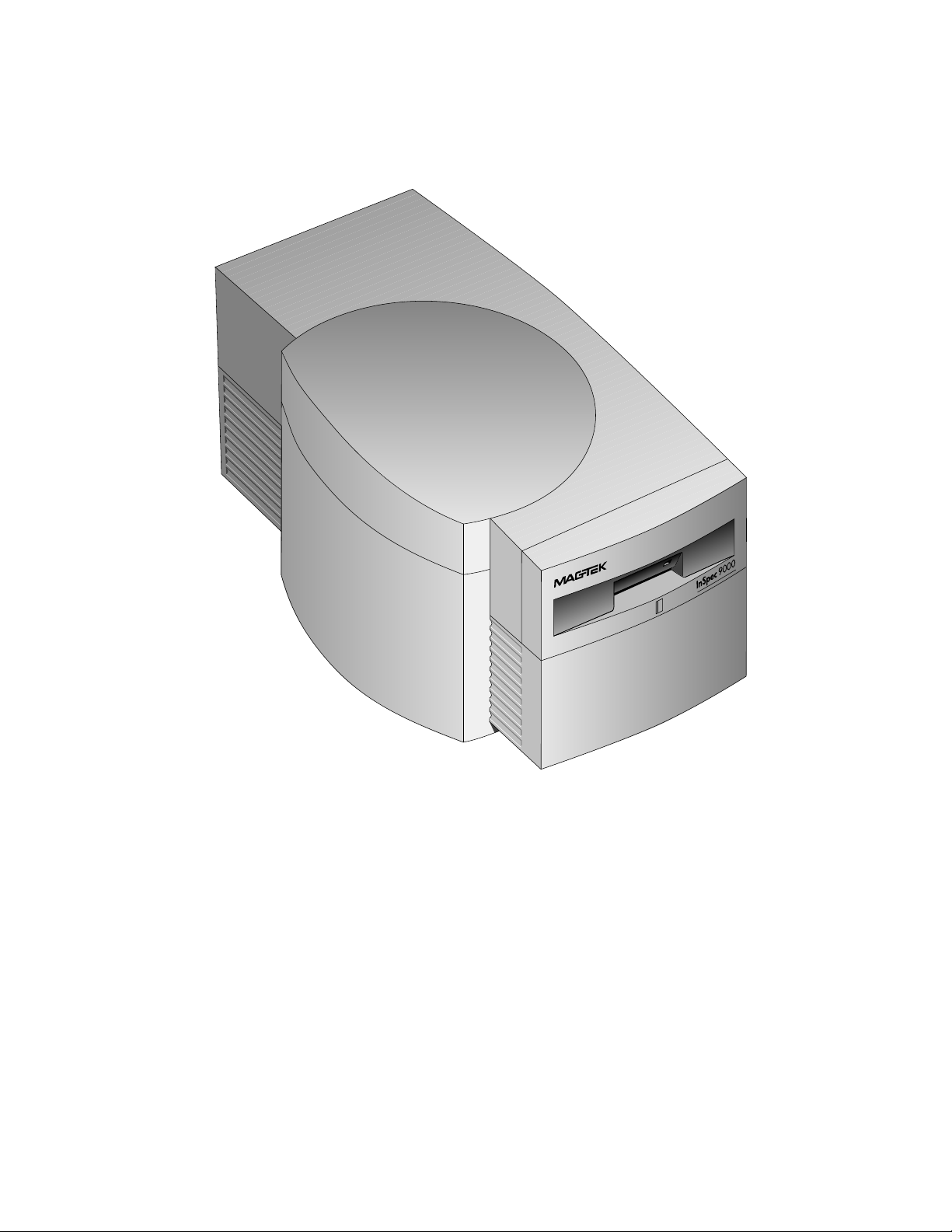
Figure 1-1. InSpec 9000 Card Tester
Page 11

SECTION 1. FEATURES AND SPECIFICATIONS
The InSpec 9000 Encoded Card Tester measures parameters of magnetic stripe encoding. The
parameters are shown on a computer screen and compared with ISO (International Standards
Organization) standards. Because the parameters are presented as graphic illustrations, they are
easy to read and easy to understand. The Tester also provides performance trends based on a
database of test results.
FEATURES
• Measures amplitude, bit size, and start sentinel, and compares results with ISO standards and
presents data in various graphs, charts and tables
• Provides previous measurements of individual cards or daily summaries to establish trends
• Presents card profile graphs of each measured parameter
• Easily installed and easy to use Windows-based software
• Uses specially provided cards for easy head cleaning
• Maintains database files
• On-site calibration from user collected data on a test card compared to a factory-provided
card
• Security password to restrict access or permit controlled use access to certain data
REQUIREMENTS
Equipment needed to operate the Tester is either supplied by MagTek or the customer. These
items are listed below.
MagTek supplied
• InSpec 9000 Card Tester hardware, P/N 39810003; Software-CD, Noise Detect, P/N
39810316
• Cable, 9 pin male Tester to 9-pin female PC Adapter, P/N 21015823
• Cable, power from Tester to wall receptacle, P/N 71100001
• Cleaning Cards, P/N 96700004
• Polishing Card, 0.5 micron (1), P/N 96700014
• Test Cards (2), P/N 96600033
• Setup Cards (2) - InSpec 9000, unit specified, P/N 96600036
• Card Extraction Kit, P/N 39814801
1
Page 12

InSpec 9000 Encoded Card Tester
User supplied
The recommended minimum requirements are as follows:
• Pentium Computer System
• VGA color monitor (resolution 800 x 600 pixels or higher)
• 8MB RAM (recommended 16MB)
• 10MB of hard disk space
• 1 Serial Port
• Windows 98, ME, NT, or 2000
• Color Printer
SPECIFICATIONS
Operational
Operating Voltage: 100 – 240 VAC
Operating Current 1.0 amp
Operating Temperature: 50oF to 122oF (+10oC to +50oC)
Humidity: 10% to 90% without condensing
Card Speed: 8 inches per second, typical
Resolution 10µ inches
Analysis Area All three data tracks excluding 0.130 inch at each end
Measure Limits Conform to ISO 7811 within Analysis Area
Mechanical
Depth: 13.3 inches
Width: 7.5 inches
Height: 7.1 inches
Weight: 8 lbs.
Card Parameters
Width and Length: Per ISO/IEC Specification 7810:1995(E)
Thickness: 0.030 in ± 0.003 in (0.76 mm ± 0.08 mm)
Note
The InSpec 9000 may not accurately read cards whose thickness and/or warpage
exceed the ISO 7810 specification. In addition, cards that are not properly
cleaned may give poor results along with contamination of the card path and
head face.
2
Page 13

SECTION 2. INSTALLATION
This section provides instructions for installing the Tester. There are five parts to the installation
of the InSpec 9000 Tester: unpacking, hardware installation, software installation, setup, and
cleaning. Because card sampling is required for production, some examples are referenced in this
section.
UNPACKING
Remove all material from the shipping carton and check the material with the shipping invoice
to ensure everything on the invoice is contained in the carton. If there is damage to the unit or
material on the invoice is missing, notify MagTek and the carrier.
Note
Retain the shipping carton and all packing material. The Tester
may be packed and shipped back to the factory periodically for
calibration or warranty service .
HARDWARE
Install the hardware as follows:
1. Place the Tester near the PC and a wall receptacle so that the cables can be installed.
Caution
Ensure power is off before plugging in cables, or
damage to equipment or the program may result.
2. Plug the cable with the 9-pin connector into the Tester and the other end to the PC Com
Port. It may be necessary to use a DB9 to DB25 adapter for the Com port.
3. Plug the power cord into the Tester and the wall receptacle.
4. Power up the computer and press the power on (I) switch on the rear panel of the Tester.
5. The LED on the front of the Tester should be green. If the LED does not come on,
check to ensure the cables are properly connected.
6. If the LED still does not light, press the power switch off, remove the cables, and check
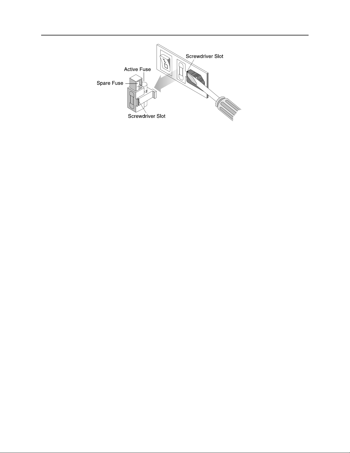
the fuse, located next to the power switch as shown in Figure 2-1.
7. Replace the fuse if necessary, reconnect the cables, and power up. If the LED still does
not light, call for technical or supervisory personnel.
3
Page 14
InSpec 9000 Encoded Card Tester
Figure 2-1. Fuse Holder
SOFTWARE
To begin the installation, insert the CD into the appropriate drive. The installation program will
automatically start. If the installation program does not start automatically, select Run from the
Start menu. Within the open field, type x:\setuup, where x: is the drive letter of your CD ROM
drive. Click OK to begin the installation. The installation program will guide you through the
setup process.
Note for International Users
The Inspec 9000 software requires regional settings be set to
English (United States). Some features may not work correctly if
other settings are used.
4
Page 15
Section 2. Installation
SETUP
To setup the unit for operation, perform the following steps:
1. From the Windows Program Manager, open the InSpec 9000 program. (If more details
are required for opening the program, refer to the next section, Operation.)
2. After the opening screen briefly flashes on the screen and the main menu appears, click
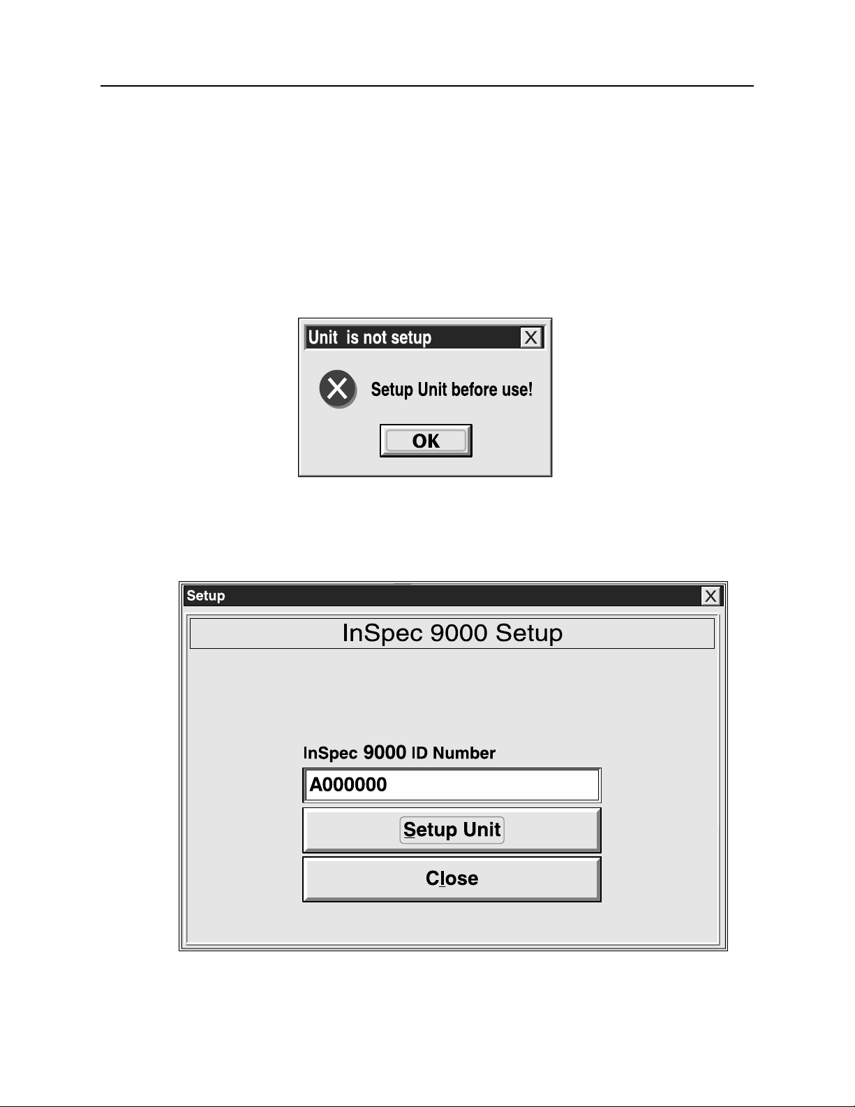
on the Read Card button. If the unit is not set up, the dialog box shown in Figure 2-2 will
appear. Error messages are listed in Appendix D.
Figure 2-2. Unit Not Set Up
3. From the Main Menu select Setup, select Hardware, then Setup and the following screen
will appear:
Figure 2-3. Setup Screen
5
Page 16
InSpec 9000 Encoded Card Tester
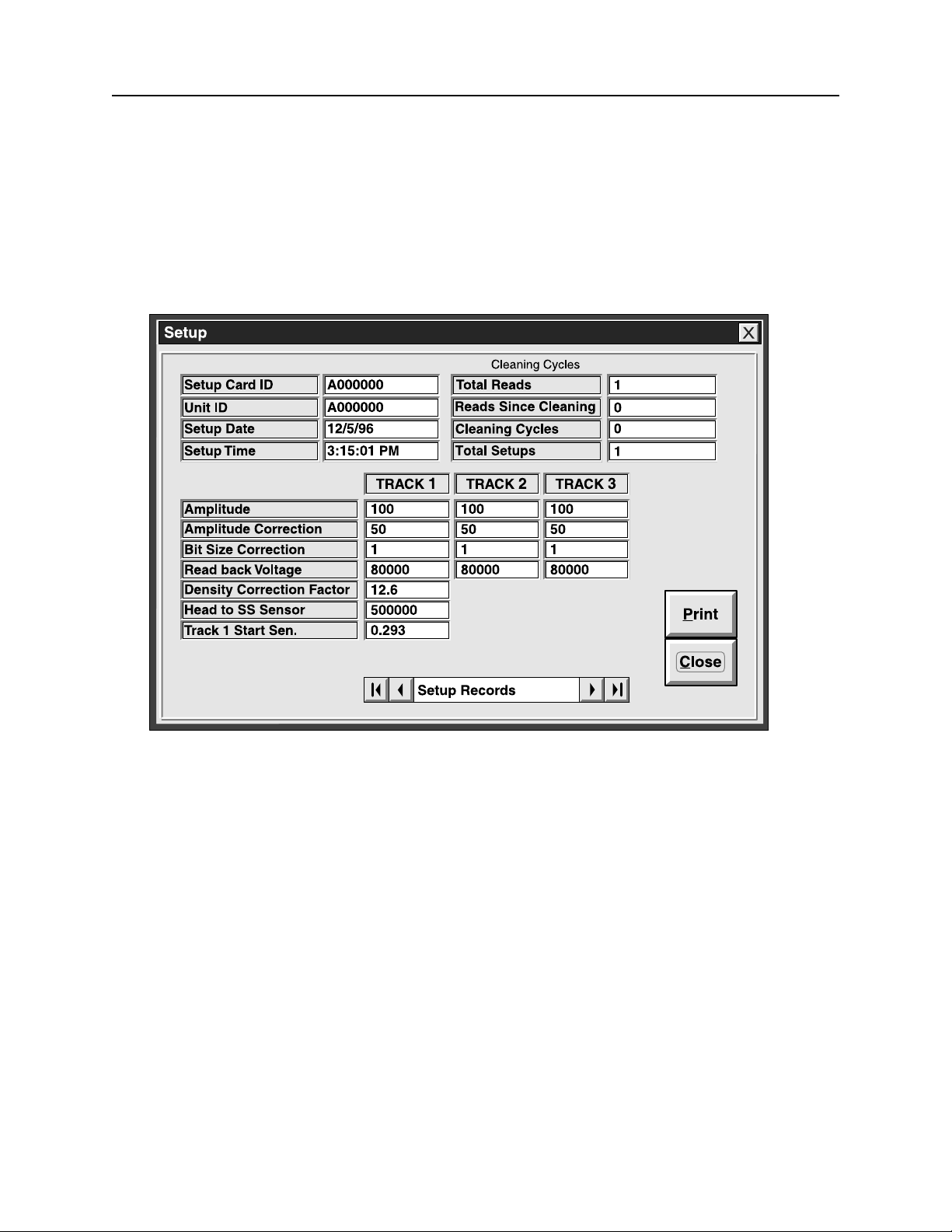
The ID number is a unique number for that unit that also identifies the firmware. If a problem
exists with the unit, this number will be needed by technical support personnel.
4. Click on Setup unit. The dialog box to appear will request the Setup Card: Insert
Setup Card No: A000000. The number that appears on the box will be the
number on the Setup Card that was shipped with the unit.
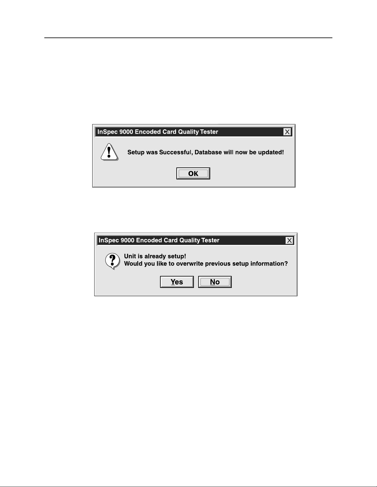
5. Insert the Setup Card, and the next dialog box to appear is shown in Figure 2-4
Figure 2-4. Successful Setup
If the unit has been previously set up, the screen shown in Figure 2-5 will appear:
Figure 2-5. Setup Previously Performed
To obtain information about the database setup, select View from the Main Menu, then Setup
Database. Figure 2-6 shows the Setup Database screen. The screen lists the identification
numbers, the date and time of setup, the total number of cards read, and the number of reads
since the last cleaning. Information at the bottom of the screen is for maintenance personnel.
Keyboard Protocol
The keyboard protocol of the InSpec 9000 follows the protocol of Windows; for example, if a
keyboard is to be used instead of a mouse, the underlined letter in the dialog box can be typed
instead of clicking on it with a mouse. In Figure 2-5, if the previous setup is to be overwritten,
instead of clicking on Yes with the mouse, type Y. Sometimes the keys Ctrl or Alt are used with
the underlined letter. Check the Windows documentation for details.
6
Page 17
Section 2. Installation
Taskbar Removal
If the taskbar at the bottom of the screen is in the way of viewing the screen, it may be necessary
to remove it. Click on Start, then Settings and Taskbar. When Taskbar Properties appears,
click on Taskbar Options, then Auto hide, then OK. The Taskbar will then go below the
bottom of the screen. To reposition the taskbar, move the cursor to the bottom of the screen, and
the taskbar will reappear.
Figure 2-6. Setup Database
CLEANING
Accurate signal amplitude measurements (described in Section 3) depend on high quality contact
between the Tester’s magnetic head and the magnetic stripe under test. If the head does not
make good contact by even a small amount, the resulting signal amplitude measurement value
will be lower than it would have been with proper contact. A separation between the head and
stripe of only 0.0005 inches (13µm) can lower the signal amplitude result by 50%.
Aside from surface distortions on the magnetic stripe or card, contamination is primarily
responsible for poor head to stripe contact.
7
Page 18

InSpec 9000 Encoded Card Tester
Offset powder sometimes used in card manufacture to prevent blocking (powder can cause a
significant decrease in amplitude and can contaminate the read head giving false readings for
many cards.)
• Packing materials; fibers from containers
• Hologram/Signature, Panel/Magnetic media particles “flash” not adhering to the card as
intended
• Cards can also become statically charged making them attract airborne dust.
Card Cleaning
To optimize test results, MagTek recommends cleaning the magnetic stripe cards with ammoniabased glass cleaner before testing.
Caution
Do not clean magnetic stripe cards with alcohol or damage to the
magnetic stripe may occur.
Head and Roller Cleaning - Standard Card, P/N 96700004
The Tester can only provide reliable results if it is clean. As a result, the Tester will issue a
warning after 50 card read cycles. When the warning is received, the cleaning procedure should
be performed. The warning will appear for each card tested until the cleaning procedure is
performed.
Caution
Do not run the 0.5-micron card (abrasive stripe) for this procedure
or damage to the cleaning card and the Tester may result.
Use the cleaning card and clean the head as follows:
1. From the Main Menu, select Options and select Clean Unit.
Note
Ensure the cleaning card is flat. If it is not flat, straighten it as
required before using.
2. When the following prompt appears,
Insert Card Fabric Side UP!
8
Page 19

Section 2. Installation
Insert the cleaning card into the Tester with the fabric side up (shiny side down) and
press Clean Unit.
3. The cleaning card will move in and out of the Tester three times. When completed,
follow the prompt:
Remove card and press OK to continue.
4. The next prompt will be:
Insert Card Fabric Side DOWN!
Turn the cleaning card over and insert it into the Tester with the fabric side down (shiny
side up).
5. The cleaning card will move in and out of the Tester three times.
6. Remove and discard the card.
Caution
Wait approximately 2 minutes before performing card analysis.
This will allow the unit to dry and thereby prevent damage to the
magnetic stripe to the next cards to be analyzed.
TEST CARDS
Two test cards are shipped with each unit for the purpose of verifying that the Tester is within
tolerance. Each card has a serial number on the face. The values that should appear when a test
card is inserted into the Tester are also listed on the InSpec 9000 Test Card Report that is
shipped with each unit. The cards are listed on the Report by serial number. Use the cards as
follows:
1. Insert a sample production card that is out of ISO specifications; that is, a card that shows
yellow or red bars on the ISO Parameters screen when it is inserted into the Tester. (See
Section 3, Operation and Section 4, Graphics Presentations.)
2. Insert a MagTek test card into the Tester, and check the ISO Parameters screen. All the
bars on the screen should be green for the test card. If there is any doubt about the
validity of the test, check the values of the test card on the screen against the InSpec 9000
Test Card Report. The values should be approximately the same*. Both should be
within tolerance. Compare the production card with the Test Card.
*Tolerances for the test cards are as follows:
• Average Amplitude = ± 15%
• Start Sentinel = ± 0.007 inch
• Average Bit Size = ± 2%
9
Page 20

InSpec 9000 Encoded Card Tester
3. If there is still some doubt about the accuracy of the Tester, run the other test card and
check the values as described in step 2. If necessary, perform the 0.5-micron head
polishing procedure below.
Head Polishing - 0.5-micron (Abrasive Card), P/N 96700014
If the Tester shows a change in amplitude of approximately 15% to 20% after the Test Card
Procedure is run, use the 0.5 micron (abrasive) head-polishing card, P/N 96700014, and clean the
head as follows:
1. With the abrasive stripe up and to the left, insert the card and click on Clean Unit.
2. The card will move in and out of the Tester three times.
Caution
Do not run the head-polishing card with abrasive stripe down, or
damage to the roller surface and the Tester may result.
3. Remove the head-polishing card from the Tester, and run the cleaning card.
Note
Do not discard the head-polishing card after one use; this card is
for multiple use.
4. Perform the Test Card procedure to ensure the Tester is within tolerance. If the results
are not within spec, call service personnel.
SAMPLING TECHNIQUES
The InSpec 9000 Encoded Card Tester is designed for a production environment; that is, samples
are taken from a large production run and tested on the InSpec 9000. The samples tested
represent a lot or batch. The lot or batch is accepted or rejected on the basis of these samples.
More than sampling lots for acceptance or rejection, the Tester also reveals problem trends with
the processes of producing, encoding, or testing cards. Because of the graphics presentations
and database in the Tester, problem trends are easier to identify. (See Section 4, Graphics
Presentations, Interpreting Performance Charts.)
There are many techniques for sampling, and the example below is commonly used in industry.
The example is taken from the following publication:
ANSI/ASQC Z1.4 - 1993, American National Standard, Sampling Procedures and Tables for
Inspection by Attributes, American Society for Quality Control.
10
Page 21

Section 2. Installation
In the following table, the "Single Normal Plan, General Inspection Level I, AQL .010"
designates the criteria used in sampling. In the Table, the Lot Size is equivalent to the card
production run; the Sample Size is the number of randomly selected cards to be run on the
Tester; the Accept and Reject columns are the number of samples for rejecting or accepting the
Lot. If, for example, Accept is 1 and Reject is 2, the Lot will be accepted if there is 1 card out of
spec, but rejected if there are 2 cards out of spec. If the Lot is rejected, the process is repeated.
If rejected again, 100% evaluation is required.
Example of Single Normal Plan, General Inspection Level I, AQL .010
Lot or Batch Size Sample Size Accept Reject
2 to 8 All 0 1
9 to 15 All 0 1
16 to 25 All 0 1
.
.
.
151 to 280 13 0 1
281 to 500 20 0 1
501 to 1200 32 0 1
The following procedure is only an example using ANSI/ASQC Z1.4 - 1993 as a guideline for
sampling:
1. Determine the Lot size, and remove the number of samples listed in the table.
2. For a Lot size of 501 to 1200, remove 32 samples and run them on the
Tester.
3. If all 32 cards are within spec, accept the Lot.
4. If 1 card is out of spec, repeat steps 2 and 3.
5. If 1 card is out of spec, test the entire Lot.
Consult ANSI/ASQC Z1.4 - 1993, for actual techniques and values for sampling.
11
Page 22

InSpec 9000 Encoded Card Tester
12
Page 23
SECTION 3. OPERATION
The operation of the Tester includes opening the tester program, cleaning, reading cards and
interpreting the results, obtaining performance charts and interpreting trends. Also included in
this section are descriptions of Windows-style buttons and Tester icons on the main screen.
OPENING THE TESTER PROGRAM
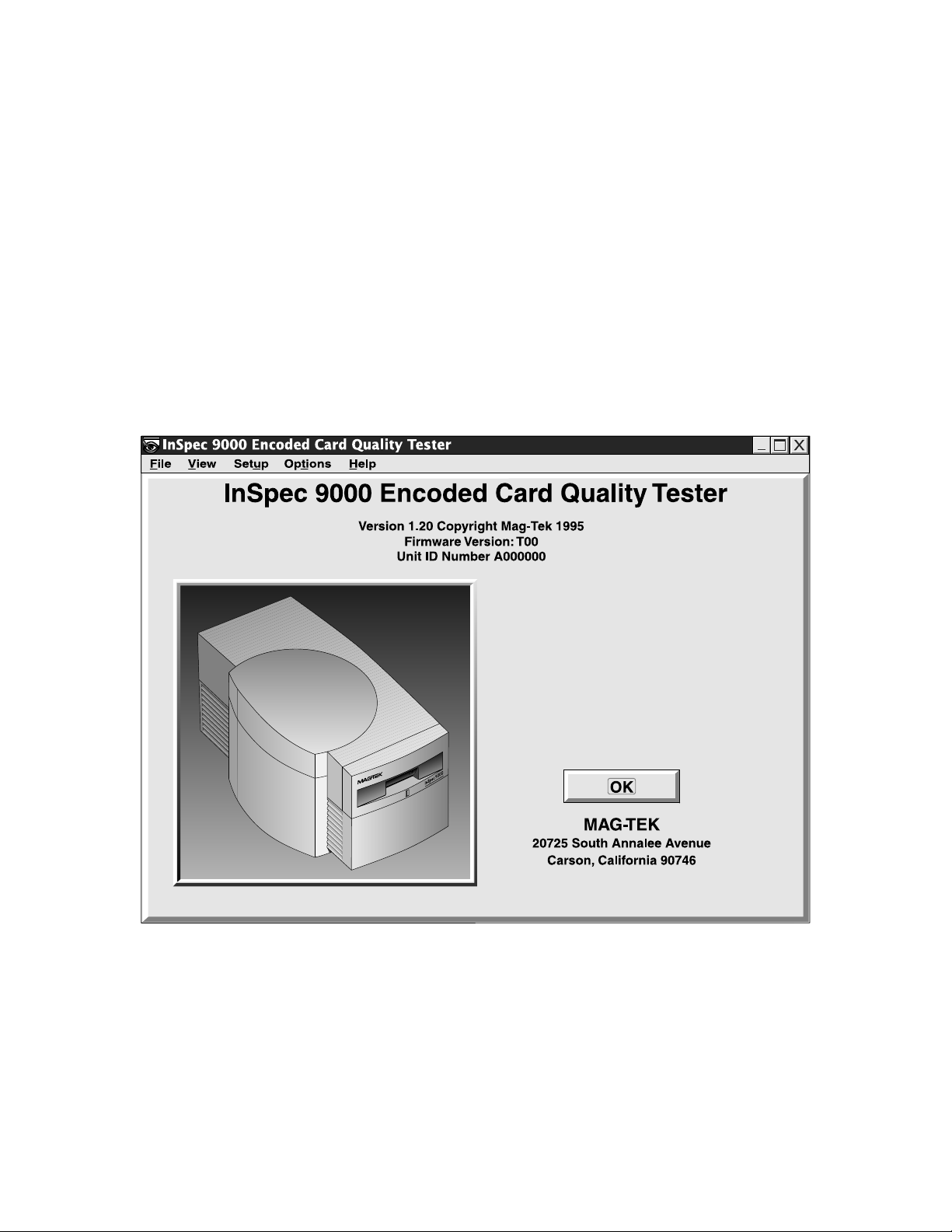
After the InSpec Tester program is opened from Windows, a picture of the Tester with the
version number will appear as shown in Figure 3-1. In this example the unit is installed, and the
firmware version number and the Unit ID are listed. When the unit is not properly installed, the
message “Unit Not Installed...” appears where the firmware and ID numbers are.
Figure 3-1. Opening Display
This screen will disappear in a few seconds leaving the main screen showing.
13
Page 24
InSpec 9000 Encoded Card Tester
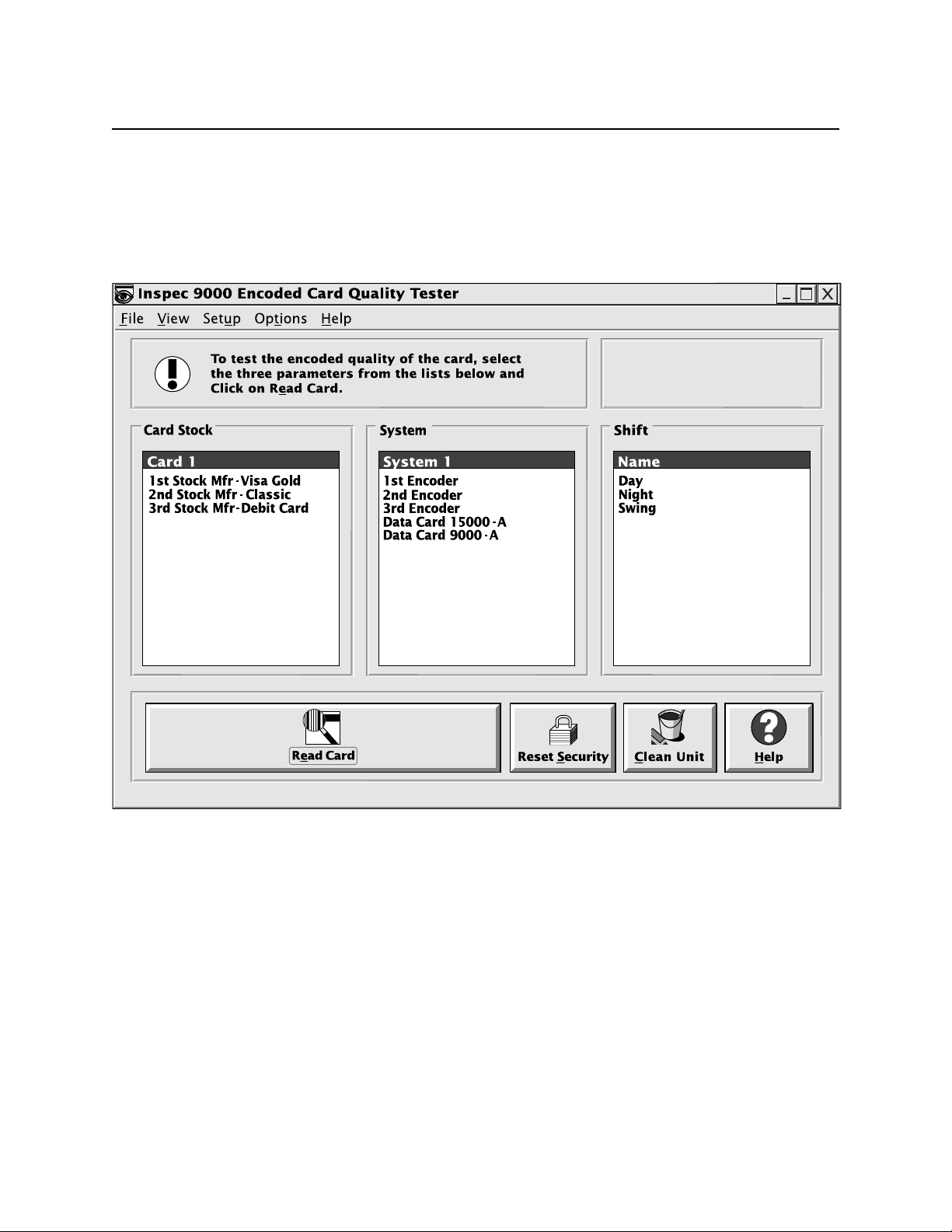
MAIN SCREEN
At the top of the main screen, shown in Figure 3-2, the buttons are similar to Windows buttons
but are specific to the Tester. The screens selected from the main screen are shown in this
section and in “Section 4. Graphics Presentations”.
Figure 3-2. Main Screen
Windows Screen
Brief descriptions of the routines that are presented by the Windows menu bar are as follows:
14
Page 25
Section 3. Operation
File
Open Card - The Open button is for a unique card-specific file used for previous card reads that
have been saved on an individual basis. Card profile charts, which are normally used by
technical personnel, are not saved in the database but may be accessed by using this button when
saved with the save button.
Save Card - The Save Card button is for a unique card-specific file used for saving a card, bar
chart, and card profile information for future reference. This does not save the card in the
database. See Section 4, “Graphics Presentations”, for a description of card profiles.
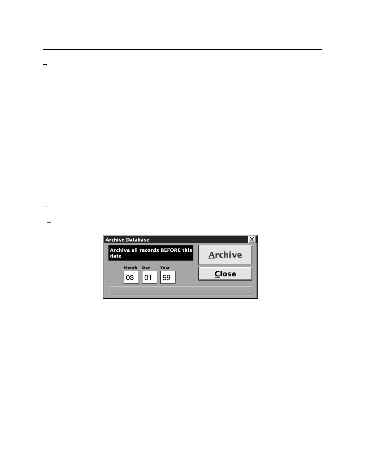
Archive Database - Allows the operator to move all data before a selected date from the database
to an archive file. If the size of the database is reduced, working with performance charts is
faster. The screen is shown in Figure 3-3. An example of the date for 2 Jan 99 is written as 01
02 99. Any year less than 90 will be considered to be after 2000; for example, 59 will be 2059;
the year 98 will be 1998. MagTek recommends the database should be archived monthly.
Reset Security – See Reset Security below.
Exit - Standard Windows exit from this program.
Figure 3-3. Archive Database
iew
V
ISO Compliance - The bar chart that appears represents the most recent card that was read. After
a graph or chart has been canceled, this button will retrieve only the most recent card viewed.
Card DataBase - The screen Card Database Search Parameters permits search of data base by
time and date, card stock, system type, and shift. When the parameters are selected, the screen
Card Database Records gives results for amplitude, bit size, adjacent bit, start sentinel, and track,
all of which are listed in Section 4 under Database.
15
Page 26

InSpec 9000 Encoded Card Tester
Setup Database - Refer to Setup in Section 2 and see below.
erformance Charts - Presents individual card or daily summary of amplitude, bit characteristics,
P
start sentinel and specified time period. This is used to obtain Performance Trend Charts which
alert the operator to take action when parameters begin to drift out of specification. The user
may also specify a printout of numerical data with all ISO parameters, or for a single Track, a
graph, a print out of the screen, or exit from the screen. For the numerical data screen, as the
cursor is positioned on each parameter, ISO specifications for that parameter appear at the
bottom of the screen.
Archived Data Charts -Permits viewing of archived data (See Archived Database above).
ISO Limits - Lists ISO limits for new cards (also called unused encoded cards) and used cards
(also called returned cards, which are cards that have been issued and returned for evaluation).
Error Log - Lists Date, Time, Error Code, Error Description, and Error Location. Used by
technical personnel for troubleshooting.
Setup
Presents screen for Software and Hardware Setup. Software includes Parameters and Security.
Parameters is for adding or removing card stock, system type, and shift as described below.
Security restricts access to certain data and is also described below. Hardware lists and permits
selection of PC Com Ports 1 through 4. If a Com Port is not selected, a dialog box will appear:
“Com port not selected. Please select a com port from the Options menu!” Refer to Section 2,
Installation, Hardware Setup for further installation setup information.
Options
Allows operator to select the functions of Clean Unit or Eject Card. When Clean Unit is
selected, a prompt appears for cleaning. When Eject Card is selected, the unit should eject the
card. If the card does not eject, see Section 5, Troubleshooting, for removing the card.
Help
Contents gives extensive on-line “How to” presentations and other operational
descriptions. About shows opening screen which lists the firmware and unit ID numbers
Read Card
Before “Read Card” is selected, selections from “Card Stock”, “System”, and “Shift” selections
must be highlighted. When the ISO screen appears, the operator may add to the
database or cancel (not add to the database). See the subsection “Reading a Card”
below.
16
Page 27

Section 3. Operation
Clean Unit
When Clean Unit is selected, the program will prompt to insert the cleaning card. Insert the card
with the soft side up (shiny side down). The unit will then move the card in and out
three times, and the head will be cleaned. To clean the rollers, turn the card over and
insert it with the soft side down (shiny side up). The unit will move the card as
previously described to clean the rollers.
Reset Security
When the software starts up, or when Reset Security is clicked, the standard restriction is
activated. The standard restriction may be changed or modified as described below
under Security.
CARD STOCK, SYSTEM, SHIFT
Before a card can be read and the information stored in the database, the card stock, system type
and shift must be highlighted. The titles “Card Stock, System, Shift” may be changed by the
user as required. To change the entries, select Setup and Software Setup from the main menu,
double click on the entry to be changed, and when the dialog box appears type in the new title
and click on OK.
To Setup the database, perform the following steps:
1. From the main screen select the Setup button then Software.
2. Under Card Stock type in the name of the card manufacturer and the batch number of the
cards, or equivalent for identification. (MagTek recommends this information. The user
may require more or less.) An example is: 1st Stock Mfr -Visa Gold.
3. Press the Add button.
4. Under System, enter the name of the encoder. MagTek also recommends the model, and
the serial number. An Example is: 1st Encoder, Mod 1, SN 12345678.
5. Press the Add button.
6. Under Shift, enter the name of the shift when the tests are performed (another entry may
be Employee).
7. Press the Add button.
8. Press the OK button.
17
Page 28

InSpec 9000 Encoded Card Tester
SECURITY
The security features in the InSpec 9000 are used to restrict access to certain data. These
features are accessed by selecting Setup from the main screen, then Software, then Security. The
current password must be entered to access the security form. The default password is
“password”. Passwords are case sensitive; p is not the same as P. The Security screen is shown
in Figure 3-4.
Figure 3-4. Security Screen
To change the current password, type the new password in the test boxes labeled New and
Confirm. Click on the OK button to change the password.
As shown above, the security features have two states, standard restriction and Administrative
Override. The standard restriction is the security level that is used when the software starts up or
the Security Reset (on the Main Screen) has been clicked. Administrative Override is to allow a
supervisor to enable the visibility of certain data for a limited time.
18
Page 29

Section 3. Operation
Once the Administrative Override has been enabled, it determines what data is visible until the
software is shut down or the Reset Security button or menu item on the Main Screen is clicked.
Display Card Data will restrict the visibility of the data encoded on the card being tested. This
data normally is displayed on the ISO compliance bar graph (Figure 3-9) and numerical
parameters (Figure 4-2). Also, the card data will not be saved in the saved file when the card
data is restricted.
Save Card to File will restrict the user’s ability to save the card read to a file. The encodingquality results of the read will still be saved into the database for statistical evaluation.
View Profile Graphs will restrict the user’s ability to view the profile graphs from the ISO
compliance (Figures 4-4 and 4-5).
Security Option is a reserved slot for future security features. It has no use at this time.
READING A CARD
On the main screen perform the following steps for the Tester to read a card:
1. Ensure selections from “Card Stock”, “System”, and “Shift” are selected by highlighting.
2. Click on the “Read Card” icon.
3. When the Insert Card! prompt appears, insert the card.
4. If the card is to be saved in the database, when the ISO screen appears, click on the Add
button. (The ISO parameters screen is shown below.)
5. If a card is blank or inserted incorrectly, a dialog box will appear: “Blank card or card
inserted Incorrectly!”. Insert the card with the magnetic stripe up and to the left, or insert
a new card.
CARD FAILURES
If the Tester does not receive the correct LRC (Longitudinal Redundancy Check) an indication
as shown in Figure 3-5 will appear on the screen. If the Parity is not correct or if both LRC and
parity are incorrect, an indication as shown in Figure 3-6 will appear on the screen. These
checks are to ensure the data on the card is decoded correctly.
19
Page 30

InSpec 9000 Encoded Card Tester
Figure 3-5. LRC Failure
Figure 3-6. LRC or Parity Check Failure
If the Start Sentinel character on a card is not found by the Tester, an indication as shown in
Figure 3-7 will appear on the screen. Although the Start Sentinel Location graph, shown in
Section 4, may indicate a position of the start sentinel, the value in the graph is the distance
calculated to the first “1” bit on the card and not the Start Sentinel character.
Figure 3-7. Start Sentinel Not Found
The Noise Detection window is shown in Figure 3-8.
20
Page 31

Section 3. Operation
Figure 3-8. Added Pulse Detected
The Noise Detection window will appear if the threshold for either “added pulse detected” or
“waveform distortion” is exceeded. This window will also appear if the threshold is exceeded
because of the combination of effects from both added pulse and waveform. This test is critical
in HiCo material testing. Exceeding this ISO limit by even a small percentage may affect read
reliability.
The ISO standards identify these two parameters, added pulse and waveform, associated with the
magnetic stripe. ISO standards 7811-2 and 7811-6 describe limits for added pulse while only
7811-6 (the HiCo document) describes waveform. Since added pulse and waveform are
characteristics of the magnetic stripe and not encoding, issuers who have prequalified their
stripes at a testing laboratory will see this window very rarely.
Note
False Added Pulses may be caused by physical damage to the
card, such as a scratch.
If this window occurs frequently, sample cards should be sent to an independent testing
laboratory requesting the absolute value of the added pulse and waveform conditions.
PARAMETERS
When a card is read, the Tester checks six important ISO parameters, which are presented
graphically, and color coded as green, yellow, and red. Figure 3-9 illustrates this concept. There
are parameters for two types of cards: one for new cards and one for used cards. New cards are
cards that have been encoded but have not been used. Used cards are cards that have been
encoded and issued, and usually used in practical applications, and returned for testing.
As shown in the illustration, the parameters are tested for Tracks 1, 2, and 3 of the magnetic
stripe. Notice that the amplitude in Track 1 is a red bar (simulated here, but red on the screen).
This indicates to the operator that the card is out of spec for both new and used cards. In all
three tracks the bit size and the adjacent bits are yellow. This indicates that the card is out of
spec for new cards but in spec for used cards. All other bars on the illustration are green, in spec
for both new and used cards.
21
Page 32

InSpec 9000 Encoded Card Tester
Figure 3-9. Max/Min ISO Parameters
The bars shown in the illustration represent maximum and minimum ISO parameter values. To
obtain the average values, click on the “Average” button. When the screen projects the average
values, shown in Figure 3-10, the button changes to Max/Min. Click on the button and the
screen changes back to the original.
The icon in the upper right corner of the screen indicates that the card may not be readable in the
field based on error messages displayed previously.
22
Page 33

Section 3. Operation
Figure 3-10. Average ISO Parameters
To select further information in the form of charts and graphs for each of the parameters, select
the buttons below the bar charts for each track. These parameters are described below and
illustrated in Section 4, Graphic Presentations. The parameters are also discussed in Appendices
A and C of this manual.
ISO Limits and Measurement Uncertainty
The ISO Limits specified under the View menu are a composite of two ISO specifications: 78112 and 7811-6. These values are the widest ISO limits of both specifications. They were selected
because LoCo and HiCo values are different, and Readers in the field read reliably with cards
encoded within these combined limits.
23
Page 34

InSpec 9000 Encoded Card Tester
As with any machine, there are also tolerances, or measurement uncertainties, ascribed to the
Tester. Measurement uncertainty limits may be found on the “ISO Limits” screen that is
accessed from the View Menu, and shown in Figure 3-11. The measurement uncertainty is at the
bottom of the screen.
Figure 3-11. ISO Limits
Amplitude
The signal amplitude is the resulting voltage as the read head passes over the flux transitions on
a track. The measure of signal amplitude is stated as a percentage of the Reference Signal
Amplitude.
24
Page 35
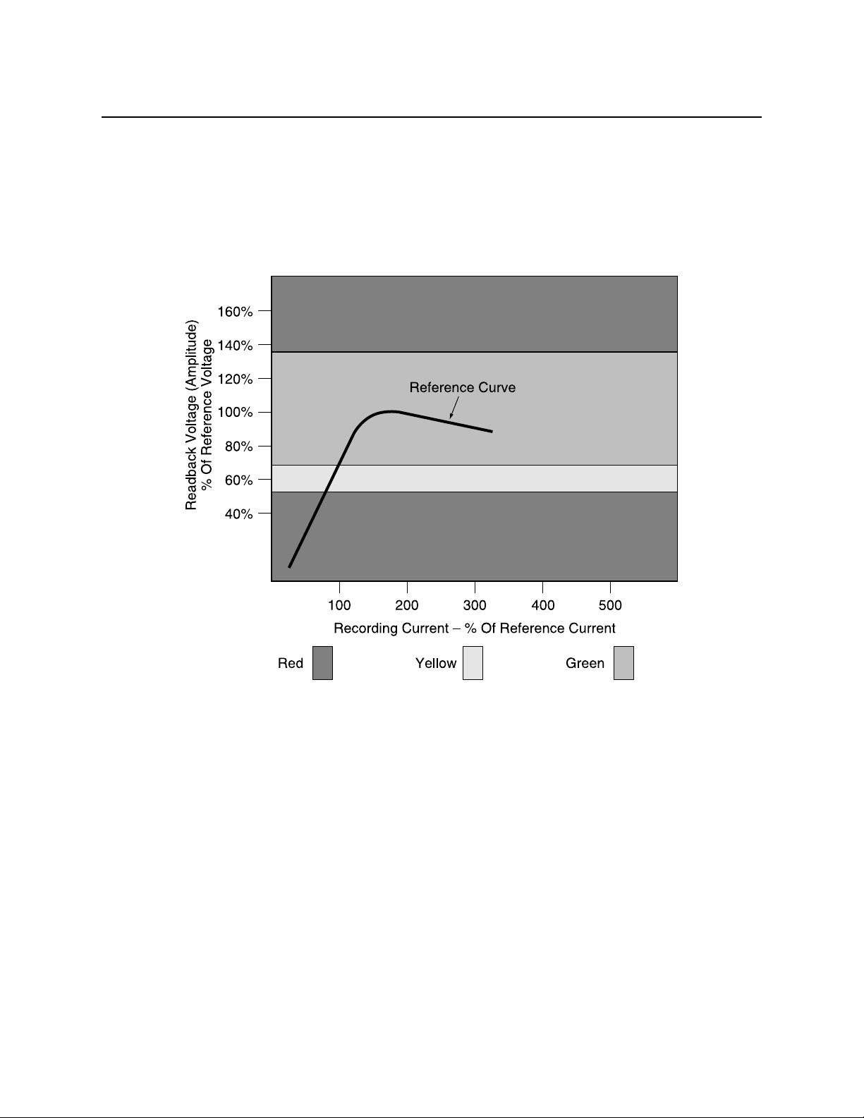
Section 3. Operation
The value of the reference signal amplitude is traceable to the Primary Standard as established
by the United States National Institute for Standards and Technology (NITS), formerly the
National Bureau of Standards. Figure 3-12 shows the reference amplitude and the related
boundaries for within spec, marginal, or out of spec. These values as well as the values for the
other parameters below are listed in Appendix C (from 7811). Composite values (from 7811-2
and 7811-6) are listed in the ISO Limits under the View Menu.
Figure 3-12. Reference Amplitude
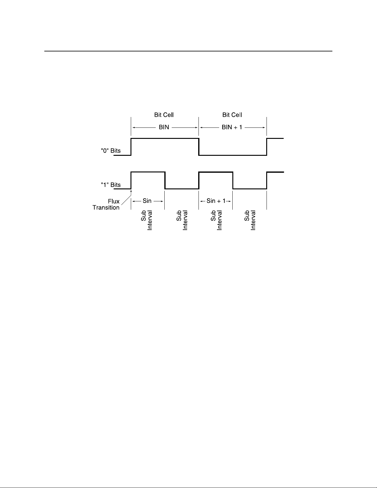
Bit Size
The bit size, or bit cell, is the distance between two clocking flux transitions. This distance is the
“zero” bit. The ISO standard abbreviates the bit size as Bin and calls it Individual Flux
Transitions Spacing Variation. Figure 3-13 shows the bit size, the subinterval, the adjacent bit
and the adjacent subinterval.
Sub. Int.
The Sub Int., or subinterval, is simply the distance of the bit cell divided by two. Two
subintervals form a “one” bit, shown in Figure 3-13 as Sin. The ISO standard abbreviates the
subinterval as Sin and calls it Subinterval Spacing Variation.
25
Page 36
InSpec 9000 Encoded Card Tester
Adj. Bit
The Adj. Bit, or adjacent bit, is the distance between the “zero” bit flux transition and the
previous bit cell, shown in Figure 3-13 as Bin + 1. The ISO standard abbreviates the adjacent bit
as Bin + 1 and calls it Adjacent Bit Cell Spacing Variation.
Figure 3-13. Bit Size
Adj. Sub.
The Adj. Sub., or adjacent subinterval, is the distance between a subinterval transition and the
previous subinterval, shown in Figure 3-13 as Sin + 1. The ISO abbreviates the adjacent
subinterval as Sin + 1 and calls it Adjacent Subinterval Spacing Variation.
Start Sent.
Start Sent., or Start Sentinel, is the distance from the edge of the card to the first subinterval flux
transition (the first one bit) encountered for each track.
26
Page 37

Section 3. Operation
CALIBRATION
The InSpec 9000 is calibrated at the factory. This calibration should last several months with
normal use. The data on the setup card that was received with the unit transfers the calibration
information to the InSpec calibration database. However, the calibration of the unit should be
periodically verified. See “Calibration Verification” below for the procedure. If calibration is
required, then a new setup card will be sent to the user by MagTek based on information
provided by the user. The procedure to obtain the required information is as follows:
1. From the Main Screen select from the following headers: Card Stock, System, Shift.
These headers have been preset at the factory for use with the “test card”.
Note
The names Card Stock, System, and Shift may have been changed
to suit the institution’s requirements (See “Card Stock, System,
Shift” above).
2. Click on the read button to read the “test card”.
3. From the ISO Parameters bar chart screen, click on “Numerical” to obtain the numerical
screen, then click on “Print”. If a printer is not available, the Average Amplitude,
Average Bit Size, and Start Sentinel values must be manually transcribed for the three
tracks. Close the numerical screen, then click on “Add” to exit from the “ISO
Parameters” bar chart screen.
4. Repeat the above until 10 reads of the “test card” are completed.
5. From the “View” menu, click on “setup database”. Click on “Print”, then click on
“Close”. Again, if a printer is not available, transcribe the information manually.
6. Copy (either manually or from a copier) the test card serial number and the data from the
form supplied with the card.
Send the printed (or written) results and the card from the above procedure to the following
address:
MagTek Technical Support
3550 Labore Rd, Suite 9
Vadnais Heights, MN 55110-5126
Ph (888) 624-8350
Fax (612) 486-8760
27
Page 38

InSpec 9000 Encoded Card Tester
MagTek will use the information to either produce a new setup card or to recommend service.
CALIBRATION VERIFICATION
Calibration may be verified by using the “test card” Supplied with the InSpec 9000. This may be
done as follows:
1. From the Main Screen select the following: Card Stock: Test Card; System: InSpec;
Shift: Test.
2. Click on the read button to read the “test card”.
3. From the ISO Parameters bar chart screen, click on “Numerical”, then compare the
average amplitude, average bit size and start sentinel values from the numerical screen to
the values for all three tracks on the form included with the cards. Check to see if the
readings are within the measurement uncertainty found at the bottom of the screen on
Figure 3-11.
28
Page 39

SECTION 4. GRAPHICS PRESENTATIONS
The charts and graphs shown in this section represent only a part of all the charts and graphs that
can be produced by the program; however, these graphs are representative of the others.
The charts and graphs are organized in the order in which they are most likely to appear. The
first bar chart, “ISO Parameters” is the first chart to appear after a card is inserted in the Tester.
From this chart the operator may select the graph or “Card Profiles” from the buttons under the
bars, such as Bit Size under Track 2. When any of the numerical buttons are pressed, the
numerical values of the bars will be shown for all three tracks. If the cursor is pointed to any
value on the numerical screen, the ISO limits for that value will appear at the bottom of the
screen. The information encoded on all three tracks will also appear on the screen. If print is
selected, all of the values will be printed out with all the ISO limits and the measurement
uncertainty of the Tester. The Start Sentinel Location screen lists values in inches and
millimeters.
The next three bar graphs are performance charts used to view trends on an individual card basis
or a daily basis.
The last charts are Card Database Search Parameters and Card Database Records. Much of the
information in these charts will be used by maintenance personnel.
29
Page 40
InSpec 9000 Encoded Card Tester
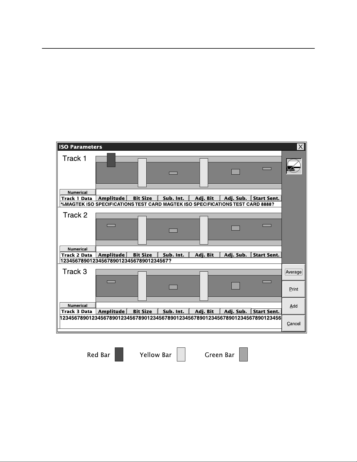
ISO PARAMETERS
The ISO Parameter chart, shown earlier, is repeated here for convenience. In Figure 4-1, the
parameters in Track 1 illustrate all three conditions: The amplitude is out of spec for both used
and new cards. The bit size and adjacent bit are within spec for used cards but out of spec for
unused cards. The subinterval, adjacent subinterval, and start sentinel are within spec for both
used and new cards.
In Tracks 2 and 3 the bit and subinterval sizes are out of spec for new cards but within spec for
used cards. Other values in Tracks 2 and 3 are within spec for both used and new cards.
30
Figure 4-1. ISO Parameters
Page 41

Section 4. Graphics Presentations
CARD PROFILES
The illustrations that follow are obtained from the ISO Parameters bar graph in Figure 4-1. To
obtain a graph of each parameter, press the button under the bar; for example, under Track 1,
press the Amplitude button under the red bar, and a screen showing the Track 1 Amplitude graph
will appear.
When the Add button is pressed, the card read is saved in the Database. If information is not to
be saved in the Database, do not press this button; press Cancel. The screen can be retrieved by
selecting View from the Main Menu and ISO Compliance.
Caution
If the information is to be saved, it is VERY important that correct
“Card Stock”, “Encoding System”, and “Shift” selections be
made BEFORE a card is entered into the reader. If this is not
done, the database and performance charts will not be meaningful.
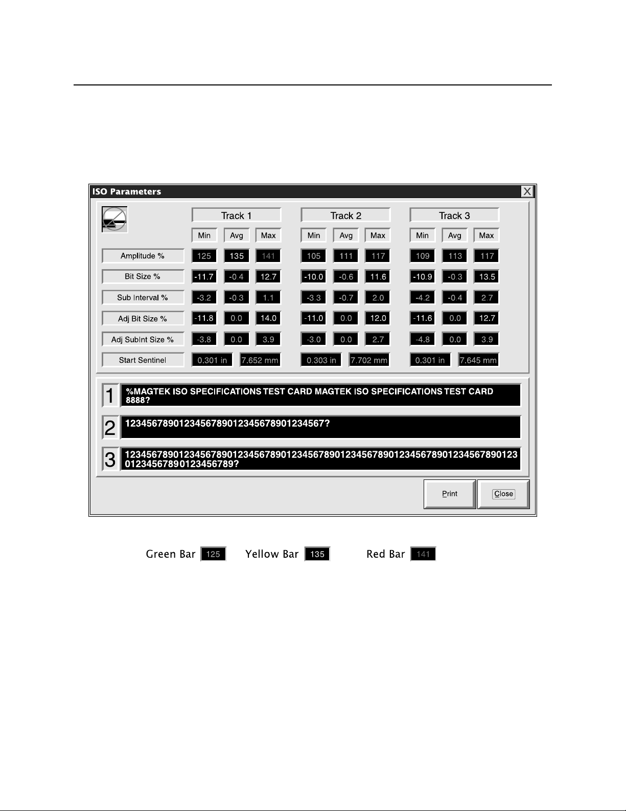
To obtain numerical data of the entire graph, click on the button marked “Numerical”, and a
screen similar to Figure 4-2 will appear.
31
Page 42
InSpec 9000 Encoded Card Tester
These numbers are the actual values of the bar charts, and they are color coded on the screen
accordingly (simulated here by shading). As the cursor is placed on any parameter number, the
actual ISO limits will appear at the bottom of the screen. The examples at the bottom of the
illustration (Green Text 125 Yellow Text 135, and Red Text 141) are shown near the top of the
illustration under Track 1 as Amplitude Min, Amplitude Avg, and Amplitude Max respectively.
Figure 4-2. Numerical Parameters
If a print is required, click on the Print button, and the results will be formatted as shown in
Figure 4-3. The screen will appear with a place for a description; this may be filled in or left
blank. The date and time will be printed. The values of the card read and ISO limits for new
cards and returned cards will be listed along with a measurement uncertainty statement that gives
the parameters (in percentage) for the Tester. The lower half of Figure 4-3 shows all limits for
cards with the colors (at the top of the columns) indicating the range of the limits; for example,
the Amplitude for Track 1 shows Red-52-Yellow-64-Green-126-Yellow-136-Red. Green falls
within 64 and 126. Red is under 52 and over 136.
32
Page 43

Section 4. Graphics Presentations
InSpec 9000 numerical test results
Description:
Date and Time Printed: 1/29/98 10:41:18 AM
Track No.: 1 2 3
Min Avg Max Min Avg Max Min Avg Max
Amplitude%: 125 135 141 105 111 117 109 113 117
Bit Size%: -11.7
Sub Interval%: 3.2 3.0 1.1 -3.3 -0.7 2.0 4.2 -0.4 2.7
Adj. Bit Size%: -11.8
Adj. Sub Bit Size%:-3.8 0.0 3.9 -3.0 0.0 2.7 -4.8 0.0 3.9
Start Sentinel (in): 0.301 in 0.303 in 0.301 in
Start Sentinel (mm) 7.652 mm 7.702 mm 7.645 mm
Green - Within ISO Limits for New Card.
Yellow - Within ISO Limits for Returned Card.
Red - Exceeds All ISO Limits
Limits
Track No.: 1 2 3
Red Green Red Red Green Red Red Green Red
Yellow Yellow Yellow Yellow Yellow Yellow
Amplitude%: 52 64 126 136 52 64 126 136 52 64 126 136
Bit Size%: -15 -10 10 15 -15 -7 7 15 -15 -10 10 15
Sub Interval%: -20 -12 12 20 -20 -10 10 20 20 -12 12 20
Adj. Bit Size%: -15 -10 10 15 -15 -10 10 15 -15 -10 10 15
Adj. Sub Bit Size%: -30 -12 12 30 -30 -12 12 30 -30 -12 12 30
Start Sentinel (in): 0.123 0.273 0.313 0.493 0.223 0.273 0.313 0.493 0.123 0.253 0.333 0.493
Start Sentinel (mm): 3.12 6.93 7.95 0.693 5.66 6.93 7.95 12.52 3.12 6.43 8.46 12.52
Measurement uncertainty of the InSpec 9000 System: Average amplitude +/-15%; Average bit size +/-2%; Start Sentinel +/-.007 inches.
To maintain the range of measurement uncertainty, the tester and card must be clean.
The card must also be flat and within ISO size specifications.
This product tests Amplitude, Jitter, Start Sentinel, and Baseline Integrity. There are other parameters that may influence read
Before testing for limits, the program removes 0.130 inch from each end of the data.
-0.4 12.7 -10.0 -0.6 11.6 -10.9 -0.3 13.5
0.0 14.0 -11.0 0.0 12.0 -11.6 0.0 12.7
reliability.
Figure 4-3. Numerical Printout
33
Page 44

InSpec 9000 Encoded Card Tester
To obtain a plot of the ISO parameters against the length of the card (in inches), click on the
Amplitude button (for example) on the ISO Parameters screen. Figure 4-4 shows the plot with
the amplitude points at distances from the beginning of the card. When the Print button is
activated, the printout will show the graph and list the minimum and maximum values for new
and used cards.
34
Figure 4-4. Amplitude Graph
Page 45

Section 4. Graphics Presentations
To obtain an illustration of the Start Sentinel location, click on the “Start Sent.” button on the
ISO Parameters screen. The location and the numerical data will be shown on the screen as
illustrated in Figure 4-5, but the screen cannot be printed.
Figure 4-5. Start Sentinel
The ISO range of the start sentinel for Tracks 1 and 2 is 0.293 ± 0.020 inch. For Track 3 the
range is 0.293 ± 0.040 inch. The vertical line through the bar illustrates where the sentinel starts
in relation to the ISO standard. If the vertical line is within the green range, it is within spec.
The yellow range indicates that the start sentinel is out of range but will still be readable in most
applications.
35
Page 46

InSpec 9000 Encoded Card Tester
PERFORMANCE CHARTS
To select and interpret a Performance Chart perform the following steps:
1. From the main screen, select View then Performance Charts.
2. From the display, select the first of the three bars (each bar will display “all”) which will
be card stock. From the list, select the stock or “All”.
3. Select the second bar and the Encoding System (the Tester) or “All”.
4. Select the third bar and the shift or “All”. The fourth bar is for status.
5. Select Daily Summary or Individual Cards.
6. Select Amplitude, Bit Size, Sub Size, or Start Sentinel.
7. Select Track 1, 2, or 3.
8. Select the Start and End Dates and Times. (Select and type in new dates or times.)
9. Select Graph.
10. After a short pause, the performance bar chart should appear on the screen.
11. If a printout is desired, press the Print button. A dialog box appears with “Use Screen
Layout” and “Layout for Printer”. If the “Screen” is chosen, the printout will contain the
same information but usually be smaller than if “Layout” is chosen. Screen is the factory
default. The default printouts will both be landscape; that is, the wide part of the page
will be horizontal.
INTERPRETING PERFORMANCE CHARTS
When interpreting performance charts, the observer looks for trends. Compilations of daily
summaries or individual cards may reveal problems with the process of producing cards, or
encoding them, or the card stock, or the encoder, or even the Tester itself (cleaning for example).
The operator should report these trends to the supervisor, the technician or other appropriate
personnel. It may be helpful to print the screen to illustrate the trend.
36
Page 47

Section 4. Graphics Presentations
Trends to observe and report are when the bars begin to drift up or down. When this occurs, the
technician may want to investigate the process for encoding the card stock, the encoder, or may
send the card or cards to a test laboratory for analysis. Cleaning and calibration of the Tester
may be in order. Figure 4-6 shows an example of card amplitude drifting up and down. Note
that the last few bars extend above the 136% maximum. This shows that some of the cards are
out of the ISO limits for new (Unused) and used (Returned) cards, but most are within limits for
both.
Figure 4-6. Performance - Amplitude
The operator should report this trend before the card extends to the limit for new cards. A graph
and print should be made of this trend. Some variations in amplitude are to be expected.
Another indication of problems is erratic changes in parameters, where a bar may be at or close
to the upper limit, and the next bar may be at or close to the lower limit. This may indicate
problems with card stock or the Encoder.
37
Page 48

InSpec 9000 Encoded Card Tester
A rising pattern for bit size is shown in Figure 4-7. The maximum limit of bit size for new
(Unused) cards is exceeded at R14 and again at R25. Technical personnel should be notified in
both instances as both limits are exceeded for new cards. At R27 the card exceeds the maximum
for used (Returned) cards. The operator should graph and print this trend.
38
Figure 4-7. Performance - Bit Size
Page 49
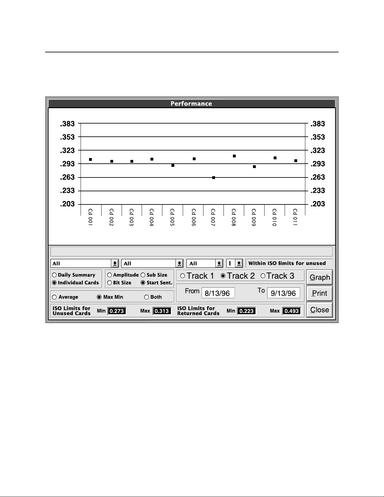
Section 4. Graphics Presentations
Figure 4-8 shows the Start Sentinel position for eleven different cards. Card 007 is at the .263
line, which is below minimum tolerance for new (Unused) cards. This particular graph does not
exhibit a particular trend.
Figure 4-8. Performance - Start Sentinel
.
39
Page 50

InSpec 9000 Encoded Card Tester
DATABASE
The database contains records of cards read.
Individual records of the card database may be accessed by first selecting Card Database from
the View Menu on the Main Screen. This screen is shown in Figure 4-9. The search can be
narrowed by selecting the specific Card Stock, Encoder, or Employee. The search may be
further narrowed by limiting the date and time.
Figure 4-9. Card Database Search
After the parameters are selected and OK is activated, the Card Database Records screen, Figure
4-10 will appear.
40
Page 51

Section 4. Graphics Presentations
Figure 4-10 Card Database Records
The first set of parameters is for identification listing the Date, Time, Card Stock, System, Shift,
and Track Number. The next set lists the actual parameter values.
The status will be 1 or 2: A number 1 means the card has been added to the database, and 2
means the card has not been added to the card database. To add to the database, press the Add
button on the ISO parameters (when a card is read). Press cancel when the card is not to be
added to the database.
Use the Record Selection bar at the bottom of this screen to start the search. The arrow with the
bar on the left locates the earliest card read for the database selection. The arrow with the bar on
the right locates the last card read. The other two arrows display one track of one card at a time
with the left arrow for earlier and the right arrow for later cards.
41
Page 52

InSpec 9000 Encoded Card Tester
42
42
Page 53

SECTION 5. TROUBLESHOOTING SECTION 5. TROUBLESHOOTING
The Troubleshooting table below lists problems and corrective actions. When a problem occurs,
The Troubleshooting table below lists problems and corrective actions. When a problem occurs,
take the corrective actions listed, and if the problem still persists, notify the responsible technical
take the corrective actions listed, and if the problem still persists, notify the responsible technical
or supervisory personnel. If the problem still persists or reoccurs, call MagTek Technical
or supervisory personnel. If the problem still persists or reoccurs, call MagTek Technical
Support.
Support.
The steps for corrective action are not necessarily sequential. Try each step and if one works,
The steps for corrective action are not necessarily sequential. Try each step and if one works,
the action is complete. Reset the unit by switching the power switch in the rear of the unit off
the action is complete. Reset the unit by switching the power switch in the rear of the unit off
then on.
then on.
TROUBLESHOOTING TABLE TROUBLESHOOTING TABLE
PROBLEM PROBLEM CORRECTIVE ACTION CORRECTIVE ACTION
Power
-No power to Tester
-No green LED
Communication Failure
One of the following messages
appear:
-“Unit Not Responding”.
-”Unit Time-out”.
-”Incomplete Data Transfer”.
Communication Port
Messages appear:
-”Communication Port not
assigned”.
-“The hardware is not available
(locked by another device)”
Hardware Failure
-Red LED.
Messages appear:
-”FPGA failure”.
-”External RAM failure”.
Card does not eject
- Card remains in Tester after
reading a card or calibrating
Tester.
For all other problems
1 Ensure power cord is plugged into a live AC (110-
220V) outlet.
2 Ensure power switch in the rear of the unit is on (I).
3 Check Fuse on rear panel (See Section 2).
4 Reset the unit by switching power off then on.
1 Ensure unit is powered up.
2 Ensure the serial cable shipped with the unit is
plugged into the back of the unit and an available
Com Port on the PC is used.
3 Reset the unit by switching power off then on.
1 From the Setup menu select the Hardware List and
choose the available Com Port on your system.
2 If the problem persists, a conflict might exist with
the Com Port devices . Refer to the PC manual
and relevant documentation.
1 Reset the unit by switching power off then on.
2. If problem persists, notify supervisory or technical
personnel then MagTek Technical Support.
1 Check to ensure power and signal cables are
properly connected.
2 From the Options menu select Eject Card several
times.
3. If still no ejection, reset by switching power on and
off several times.
4. If still no ejection, ensure power is off, and use the
card extraction tool as described below.
5 Reset the unit by switching power off then on.
Notify supervisory or technical personnel then call
MagTek Technical Support.
43
Page 54

InSpec 9000 Encoded Card Tester
CARD EXTRACTION
The card extraction tool (CET) is a slim rod with a handle on one end and a hook on the other.
The handle and the hook are oriented in the same plane.
Remove the card as follows:
1. Perform the other “Card does not eject” procedures in the Troubleshooting Table before
using the extraction tool.
Caution
Ensure power is off before inserting the tool or the unit may become damaged.
2. Press the power switch off (O).
3. Orient the Card Extraction Tool so the hook and handle are in a parallel plane with the
card as indicated in Figure 5-1.
Figure 5-1. CET Orientation
4. Insert the tool up to the handle as shown in Figure 5-2.
Figure 5-2. CET Insertion
44
Page 55

Section 5. Troubleshooting
5. Rotate the tool 90° downward as indicated in Figure 5-3
Figure 5-3. CET Rotation
6. Pull the tool until the card can be removed as indicated in Figure 5-4. If tool does not
capture the card edge, the tool may be under instead of above the card. Reinsert the tool
and rotate the handle 900 upward.
Figure 5-4. CET Extraction
7 Repeat 3 through 7 until card edge is captured. Pull the tool out until the card can be
removed. Remove the card before removing the tool.
Caution
The card and tool can not be removed together and if forced,
damage may occur to the card, the unit, or the tool.
8. Rotate the tool to the horizontal position and remove it from unit.
9. Turn the power on.
45
Page 56

InSpec 9000 Encoded Card Tester
46
Page 57

APPENDIX A. MAGNETIC ENCODING
This Magnetic Encoding Primer is intended to provide the reader with a basic understanding of
mag stripe cards and magnetic encoding. The subject of magnetic stripe encoding involves many
technical parameters that are often complicated and confusing. We will attempt to bring these
parameters into perspective as we discuss basic magnetism, how encoding and reading heads
work and the important aspects of magnetic media construction. First, we'll start with a brief
history lesson.
HISTORICAL BACKGROUND
Magnetic recording technology began in the late 1800's. Many scientists, throughout the next
half century, whose field involved electricity or magnetism, discovered the fundamentals that
magnetic stripe cards rely on today.
At the Paris Worlds Fair in 1900, Valdemar Poulsen demonstrated a magnetic wire recording
device. This device permitted voices to be recorded on an iron wire for later playback. Similar
devices were used aboard German submarines during the first World War as a means to transmit
secret voice information by recording the message at normal speed and then transmitting the play
back recording in reverse at higher speeds.
In 1928, a German patent was filed on a coating of iron particles on a strip of paper as a
recording medium and a machine that used such a strip. The German Magnetophone was
exhibited in Berlin in 1935.
After World War II, rapid growth in magnetic tape and recording occurred. Minnesota Mining
& Manufacturing (3M) started delivering iron oxide tapes in 1947, while Ampex began
delivering sound or "audio" recorders in 1948.
Meanwhile, a breakthrough in calculating machines came in 1944 when at Harvard University an
electromechanical calculator was developed that utilized binary arithmetic. "Binary" refers to a
counting method that only has two states; ON and OFF or in terms of numbers ONE and ZERO.
In 1951, the first commercial computer, UNIVAC I, was produced. Computers soon began to
utilize the memory storage ability of magnetic tape. Since computers function by manipulating
ONE bits and ZERO bits, only these two states needed to be stored. The technology of "digital"
recording was born. While the digital method of recording was similar to audio recording, it
differed in the amount of drive current used in the recording head. Audio recording relies on
varying the amplitude of the desired "signal", in order to reproduce both loud and quiet passages
as occurs in music. Digital recording relies on an even amount of signal amplitude. By
"saturating" the magnetic tape, the resulting signal amplitude remains fairly constant. This is a
key concept for our later discussion of how cards are recorded and read back.
47
Page 58

InSpec 9000 Encoded Card Tester
The key interchange parameters, that card readers rely upon, are Signal Amplitude and Jitter.
These parameters are measured by the Encoded Card Quality Tester and are defined and
explained in the pages that follow. First, some basic concepts are presented.
BASICS OF MAGNETIC RECORDING
Digital magnetic recording requires three basic components for the technology to be worthwhile:
the Recorder (or Encoder), the Magnetic Tape, the Reader. We will first focus our attention on
the Magnetic tape as it is the fundamental component from which the Encoder and Reader are
designed to work.
Magnetic Tape
A discussion of magnetic tape must first start with the tape's most basic ingredient: Iron.
Modern magnetic tapes are made with various types of iron (ferrites) or metal oxides. However,
before we complicate matters further, an understanding of iron, the basic element in any
magnetics discussion, is needed.
The fundamental characteristic of iron is its ability to become magnetized when subjected to a
magnetic field. As you know, a direction finding compass works because the Earth has magnetic
fields directed toward the North Pole. Magnetic fields can also be created by the flow of electric
current. Electric current is the fundamental way that magnetic fields are controlled and directed
in billions of products. A coil of wire, wrapped around an iron rod, will produce a magnetic
field when a DC (Direct Current) current flows through the wire, as illustrated in Figure A-1.
48
Figure A-1. Magnetic Field
Page 59
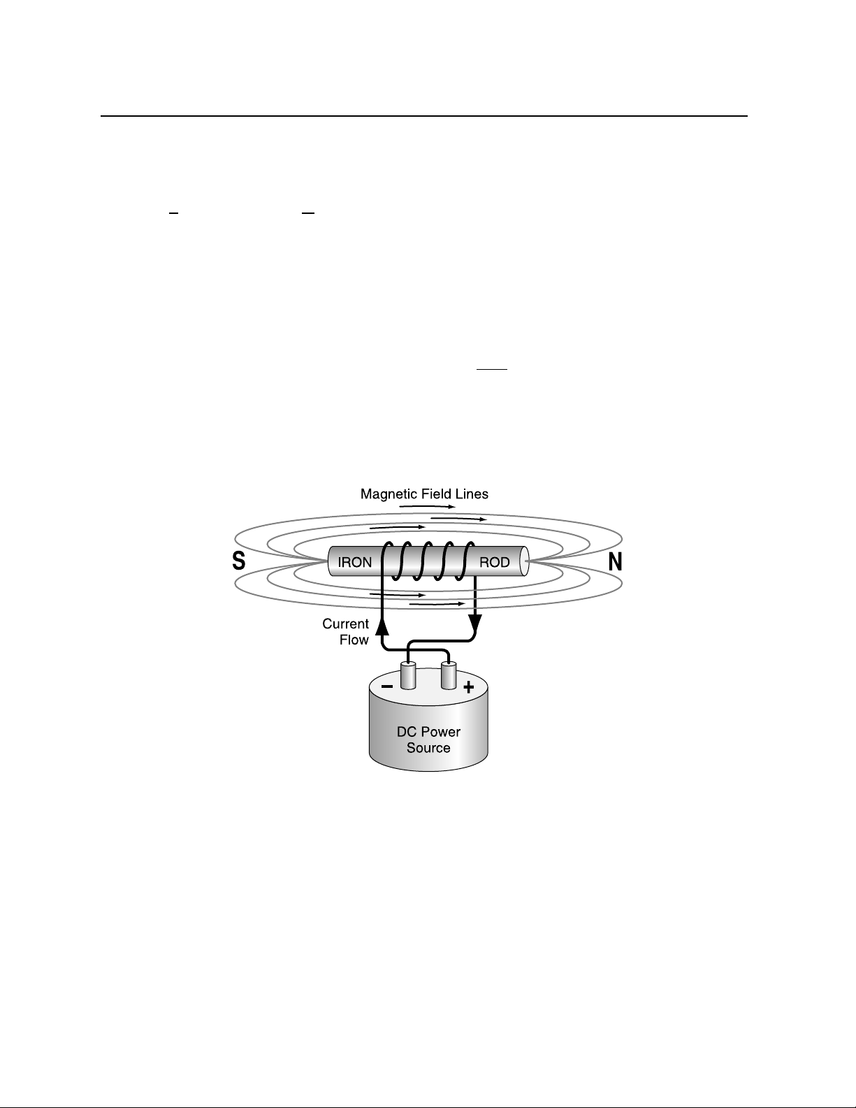
Appendix A. Magnetic Encoding
The magnetic field is directional like a DC current is directional. The convention for describing
the direction of DC current flow is for electrons to flow from the positive (+) terminal to the
negative (-) terminal. Similarly it is also conventional to describe magnetic field lines as going
from the "South Pole" to the "North Pole".
Now, back to our iron rod and wire coil. Disconnecting the current source will not stop the
magnetic field, since the iron itself has become magnetized. The magnetic field lines will be the
same as shown in Figure A-1.
This ability of iron to retain the magnetic field created by the wire coil and electric current is the
fundamental element in any magnetic media's ability to store information. The key concept here
is the ability of iron to keep or retain the magnetic field after the electric current has been
removed.
We can reverse the magnetic field direction by reconnecting the DC power source so that the
current in the wire coil flows in the opposite direction, as shown in Figure A-2.
Figure A-2. Reverse Polarity
Again, disconnecting the DC current source will not stop the magnetic field since the iron itself
has become magnetized, now in the opposite direction.
49
Page 60

InSpec 9000 Encoded Card Tester
Think of the iron rod as a "bit". We can define the left to right direction of magnetization as a
ONE bit and right to left direction as a ZERO bit. In order to make this iron rod useful as a
storage device, we need to sense the magnetic field direction in order to determine whether the
bit is a ONE or ZERO. This single bit, iron rod storage device is far from practical in today's
world where hundreds of megabytes (a million bits) of disk storage is common place and
relatively inexpensive. However, we do want to take this iron rod concept further.
Modern Magnetic Tape
A means to compact or compress a bunch of iron rods is necessary for magnetic recording to be
practical. This is done by grinding up the iron rod into a powder. This iron (or ferric) powder
forms the basic magnetic component of all magnetic media. The magnetic powder goes through
a complex process of oxidation resulting in an iron oxide called gamma ferric oxide (γFe
2O3
).
Gamma ferric oxide is the most commonly used magnetic particles for "low coercivity" magnetic
tape. ("Coercivity" is described later.) When mixed with a liquid "binder", the iron oxide can
then be coated onto a number of "substrates". Typically, for plastic card manufacture, the
substrate is a polyester film which is later slit to narrow widths for transference to cards or for
direct application on cards.
Encoding Process
The electric current used to produce a magnetic field in the iron rod is also used with an
encoding "head" to generate a magnetic field to magnetize the magnetic tape in order to store
ONES and ZEROES. Figure A-3 shows the internal workings of a typical encoding head.
50
Figure A-3. Encoding Head Model
Page 61

Appendix A. Magnetic Encoding
Notice in the figure that a coil of wire is wrapped around an iron core and that the iron core is
shaped much like a "horse shoe" magnet with the North and South Poles close together. The gap
between the North and South Poles is where the magnetic field lines are produced (when electric
current flows) and thus, it is the area of the head that touches the magnetic tape. When the
power source changes the direction of the electric current, the magnetic field lines also change
directions. This change of magnetic field direction produces a flux transition on the magnetic
tape.
To illustrate this point, refer to Figure A-4, an idealized model for magnetic tape:
Figure A-4. Magnetic Tape Model
This idealized model shows the iron oxide particles, all uniformly shaped as tiny bar magnetics
and all perfectly aligned.
Now, consider that an encode head has passed over the magnetic tape and the direction of the
electric current in the encode head coil has changed as indicated in Figure A-5.
Notice the change in the magnetic polarity on the magnetic tape where the change in encode
current occurred. This change in polarity is called a flux transition and it is what a READ head
will detect as it passes over the magnetic tape.
So, imagine a READ head passing over the magnetic tape. A READ head is basically
constructed in the same way as an encode head - “horse shoe” shaped iron with a coil of wire.
However, instead of a current being sent through the coil by a power source, an electric current
is created in the coil as the gap of the READ head passes over the flux transitions. A read back
signal is generated as illustrated in the figure above. This read back signal forms the basis for
the measurement of the position precision of the flux transitions (jitter).
This point needs to be emphasized. It is the basis for all the measurements taken by the Encoded
Card Tester: The flux transitions recorded by the encode head, on the magnetic tape, causes a
read back signal to be generated by the read head. This signal possesses amplitude whose peaks
define the position of flux transitions.
51
Page 62

InSpec 9000 Encoded Card Tester
Figure A-5. Flux Transitions
It is important to understand the basic characteristics of magnetic tape and how they relate to
recording and readback.
Magnetic Tape Characteristics
Imagine an encode head, as it passes over a length of magnetic tape, having current “driven” into
the head wires which changes at a rate of 200 times per inch (200 flux transitions per inch -200
ftpi) at ever increasing current levels. Figure A-6 illustrates this current:
Figure A-6. Encode Current Level
52
Page 63
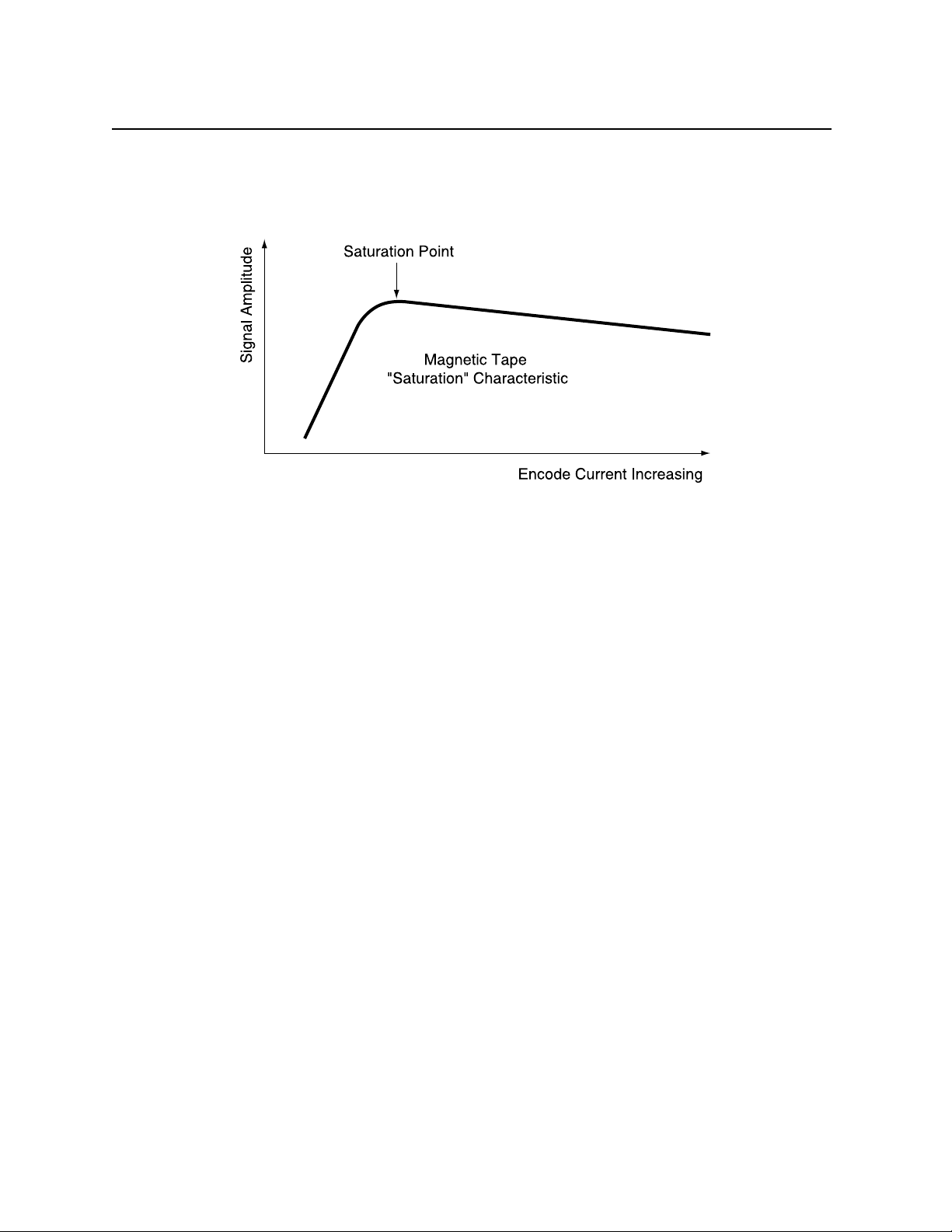
Appendix A. Magnetic Encoding
After recording a magnetic tape with this increasing current, as shown above, we can then Read
the signal amplitude peaks and plot the peak values as a function of the encode current level.
The resulting plot is shown in Figure A-7.
Figure A-7. Signal Amplitude
This plot is known as the magnetic tape’s saturation characteristic. Notice that the Signal
Amplitude increases linearly as the encode current increases until it reaches a maximum value
where afterwards the Signal Amplitude decreases slowly with ever increasing encode current.
The maximum value of Signal Amplitude on this plot is called the saturation point of the
magnetic tape.
As a point of interest, the region of the magnetic tape’s saturation characteristic, before
saturation is the region where audio or sound recordings take place. That is, audio recorders
limit the amount of recording current so that when loud passages are recorded, the playback
signal amplitude is the greatest while quiet passages generate small currents and yield small
levels of signal amplitude. Digital recordings utilize the region after the saturation point. We
will continue this discussion in the next section on Digital Magnetic Recording.
53
Page 64

InSpec 9000 Encoded Card Tester
DIGITAL MAGNETIC RECORDING
Digital recording utilizes the region of the magnetic tapes characteristic past the saturation point
where the signal amplitude does not change much with encode current. This is important, not
because encode currents vary, but because encode heads and magnetic tape are not always in
perfect, intimate contact during the encoding process. The magnetic field strength from the
encode head gap decreases significantly as the distance increases from the gap. Thus, digital
recording can withstand small “spacing losses” between the encoding head and magnetic tape.
Saturation recording (digital recording) also produces fast, sharp rise times in the read back
signal, making detection of the positions of the flux transitions more accurate.
Spacing losses occur when the encoding head leaves contact with the magnetic tape.
Contamination on the magnetic tape surface or the encoding head can produce spacing losses.
Contamination can be classified in two categories. One, loose debris (dust, plastic shavings)
which resides on the surface of the magnetic stripe causing the head to bounce or otherwise lose
contact with the magnetic stripe surface. The second type is deposits of oil, plasticizer or other
film type deposits which create a surface that causes the encoding or reading head to stick then
slip across the magnetic stripe. These oily film deposits can be thick enough to cause spacing
losses and thus can cause read or encode failures.
F2F Encoding
There are several schemes used to record or encode ones and zeros in the computer industry.
(We use the term record and encode synonymously.) In the card industry the International
Standards Organization (ISO) has defined F2F as the encoding scheme for cards. F2F stands for
frequency - double frequency, or for the purist - two frequency coherent phase recording. F2F
encoding provides for self-clocking data. That is, the serial data stream consisting of one and
zero bits provides the timing information for the reader to determine which bit is which.
The key feature of self-clocking data is that the data bits can be extracted from the serial data
stream without the need to control the speed of the magnetic media past the encoding head.
Thus, card swipe readers, where a human hand is passing the card through the read slot can work
regardless of how fast or slow the card is passing through the slot. Serial data merely means that
the one and zero bits, that form the desired characters, are stored on the same track, one bit after
the next bit.
F2F is an encoding technique which places flux transitions on the magnetic stripe separated by a
defined distance for zero bits and one half that distance for one bits.
The defined distance for Track 1 is 0.0047619 inches for zero bits. This value is the reciprocal
of the bit density of Track 1 - 210 bits per inch. For one bits - 0.0023809 (1/2 the zero bit
distance.)
54
Page 65

Appendix A. Magnetic Encoding
The defined distance for Track 2 is 0.013333 inches for zero bits. This value is the reciprocal of
the bit density of Track 2 - 75 bits per inch. for one bits - 0.0066665 inches (1/2 the zero bit
density.)
Figure A-8 illustrates this concept.
Figure A-8. Bit Cell - Flux Transition
The encoding device has the responsibility to separate the flux transitions at the proper distance.
Variations in the proper distance between flux transitions is what is commonly referred to as
jitter. Jitter is described later in this section; but first, the following is a description of the
general encoding format on each of the ISO tracks.
Before the desired information can be stored (encoded) on the card, many things must happen.
The information itself (the alphanumeric characters for Track 1 and the numeric characters for
Tracks 2 and 3) needs to be coded. That is, the information must be converted to one and zero
bits. The one and zero bit code for each character can be found in the Coded Character Set
tables in ISO/IEC 7811-2. These tables define the pattern of the one and zero bits for each
character. There is a special bit that is added to each character code for the purpose of error
detection. This special bit is called a parity bit. The parity bit is either a zero bit or a one bit
depending on whether the number of one bits in the character is an even number or and odd
number. The ISO standard has defined that for all tracks odd parity is maintained on each
character.
55
Page 66

InSpec 9000 Encoded Card Tester
This means that if the character has an odd number of one bits in the character code for that
character, the parity bit is then a zero bit. On the other hand, if the character has an even number
of one bits in the character code for that character, the parity bit is a one bit causing the total
number of one bits to be odd. Thus the term odd parity.
Before the first character (or more specifically, the first series of bits that define the desired first
character) can be encoded, a Start Sentinel character needs to be encoded. The Start Sentinel is a
defined series of bits which signal the start of the data bits. Track 1 Start Sentinel consists of
seven bits (as all characters on Track 1). Track 2 Start Sentinel consists of five bits (as all
characters on Track 2). As an example, the Track 2 Start Sentinel code is: 11010.
After the last data character is encoded, an End Sentinel must be encoded. The End Sentinel is a
defined series of bits which signal the end of the data bits. Immediately after the End Sentinel, a
special error checking character is also encoded. This error checking character is called the LRC
- Longitudinal Redundancy Check character. For further details of the LRC see Appendix B,
Glossary of Terms.
Before the Start Sentinel character and after the LRC character, “clocking bits” are encoded.
These clocking bits provide card readers with timing to start their synchronization process before
encountering the start sentinel (or end sentinel for reverse reading). Figure A-9 illustrates the
relative location of all the characters previously discussed.
Figure A-9. Card Coding
Note that as you look at the diagram, while not to scale, the encoded information does travel
from right to left along the length of the magnetic stripe.
56
Page 67

Appendix A. Magnetic Encoding
There is one more important parameter that the Tester measures. It deals with the position of the
Start Sentinel from the physical right hand edge of the card. The ISO standard requires that the
“center line” of the first bit in the start sentinel on either Track 1 or 2
to be 0.293 inches ± 0.020”
from the right hand edge of the card. The ISO standard allows the tolerance for the Start
Sentinel position on Track 3
to be ± 0.040”. The reason the start sentinel position is important is
because it provides the reader with enough leading clocking bits for synchronization and an
expectation for where valid data starts from the physical edge of the card.
The F2F encoding technique also permits reading in reverse. That is, instead of passing the card
across a read head with the start sentinel first, it is possible to pass the card across the read head
with the LRC and end sentinel first. Whether any particular reader can function in reverse
depends on whether it was designed to do so.
Next, the parameter “jitter” and why it is an important parameter to measure and control. The
Tester measures jitter and reports values for each of the jitter terms described below.
Jitter
Jitter is a term used as a short version for: Variations in Flux Transition positions. Jitter is more
precisely stated in the ISO standard as Flux Transition Spacing Variation, Subinterval Spacing
Variation, Adjacent Bit Cell Variation, and Adjacent Subinterval Spacing Variation, Bin+1 for
Adjacent Bit Cell Variation and Sin+1 for Adjacent Subinterval Spacing Variation. We will use
the ISO shortened terms (Bin, Sin, Bin + 1, and Sin +1) in this section. All four parameters have
one thing in common. They are all distance measurements between flux transitions. While all
four parameters are distance measurements, it is common to state the measured value in terms of
a percent.
Average Flux Transition Spacing Variation - Ba
This term means a measurement of the overall or average bit density for the encode track.
Individual Flux Transition Spacing Variation - Bin.
Flux Transition Spacing Variation is the distance measurement between clocking flux transitions
or Zero Bit flux transitions over the bit density for the track.
For example, if the distance between the flux transitions for a Zero bit on Track 1 measured to be
0.004350, the Flux Transition Spacing Variation would be stated as -8.7% meaning that the flux
transition that made a zero bit were 8.7% too close together.
57
Page 68

InSpec 9000 Encoded Card Tester
Note that a positive value indicates that the flux transitions were farther apart than the ideal bit
density value. A negative value indicates that the flux transitions were closer together that the
ideal bit density value.
The mathematical formula for this parameter is shown below along with the quantities for this
specific example:
Clocking or Zero Bit Distance flux transition
between Flux Transitions - 1 x 100 = % spacing variation
1/Bit Density (Bin)
For this example:
0.004350” - 1 x 100 = -8.7% flux transition
0.004762” spacing variation
(Bin)
Graphically, the definitions for Bin, Bin + 1, Sin, and Sin +1 are shown in Figure A-10.
58
Figure A-10. Bit Cells for 0 and 1 Bits
Page 69

Appendix A. Magnetic Encoding
Subinterval Spacing Variation -Sin
Subinterval Spacing Variation is the distance measurement between a subinterval transition over
one half the bit density for the track.
The mathematical formula for Sin is as follows:
Distance between a Flux Subinterval
Transition and Subinterval - 1 x 100 = % spacing variation
1/(Bit Density x 2)
Adjacent Bit Cell Spacing Variation - Bin + 1
Adjacent Bit Cell Spacing Variation* is the distance measurement between Zero Bit flux
Transitions over the previous bit cell for the track.
Clocking or Zero Bit Distance Adjacent Bit
between Flux Transitions -1 x 100 = % Cell
Previous Clocking or Zero Bit variation
Distance between Flux Transitions (Bin + 1)
*Adjacent bit cell spacing variation is also called Bit-to-Bit Jitter or BBJ
Adjacent Subinterval Spacing Variation - Sin + 1
Adjacent Subinterval Spacing Variation is the distance measurement between a subinterval
transitions over the previous subinterval.
Distance between a Flux Adjacent
Transition and Subinterval -1 x 100 = % Subinterval
One Half of Previous Bit variation
(Sin + 1)
59
Page 70

InSpec 9000 Encoded Card Tester
60
Page 71

APPENDIX B. GLOSSARY
Adjacent Bit Cell Variation
See "Jitter"
American National Standards Institute (ANSI)
The United States national standards organization. ANSI also serves as member body to
the International Standards Organization (ISO).
BBJ
See "Jitter"
Bit-to-Bit Jitter
See "Jitter"
Bpi
Bits per inch - a measure of the number of bits (bit-cells) per inch on the magnetic stripe
track. This parameter is not the same as ftpi since, for example, ISO Track 1 possesses
210 bpi encoding density. The number of flux transitions per inch for ONE bits is 420
ftpi.
Bpmm
Bits per millimeter - a measure of the number of bits (bit-cells) per millimeter on the
magnetic stripe track. This parameter is not the same as ftpmm since, for example, ISO
Track 1 possesses 8.27 bpmm encoding density. The number of flux transitions per
millimeter for ONE bits is 16.54 ftpmm.
Character code
The information to be recorded or encoded on the magnetic stripe are a series of
characters (for Track 1, alphabet characters and numerals are accommodated where as on
Track 2 & 3 only numerals are permitted). These characters are reduced to ONES and
ZERO bits by the track's character code. For Track 1, a 7-bit code is defined (6 data bits
and one parity bit) For Track 2 & 3 a 5-bit code is defined (4 data bits and one parity bit).
The specific codes for each character can be found in ISO/IEC 7811-2.
Clock transition
A flux transition marking a bit-cell boundary.
Coercivity
A measure of magnetic field strength necessary to effect a change in the magnetic field
direction of the magnetic material.
61
Page 72

InSpec 9000 Encoded Card Tester
Density
The number of bits encoded per unit length usually expressed in bits per inch, Bpi or bits
per millimeter, Bpmm.
End sentinel
The character which signals the end of the data field on an encoded track.
Flux transition
A reversal of magnetic field direction (polarity) on a magnetic stripe track. The flux
transition on the stripe is caused by reversal of current flow in the encoding head during
the process of encoding.
Flux transition spacing variation
See "Jitter"
Ftpmm
Flux transitions per millimeter - a measure of the density of recording on a magnetic
stripe track.
Ftpi
Flux transitions per inch - a measure of the density of recording on a magnetic stripe
track.
High-Co or HiCo
Colloquial term for high coercivity magnetic recording material. Typically, the value of
high coercivity media is considered to be between 2500 to 5000 oersted (typically 2500
to 4000 for ISO 7811-6 compliance).
International Standards Organization (ISO)
The international organization made up of national standards bodies and under whose
auspices international standards are developed and published.
Jitter
Term used to describe a variation in the perfect placement of flux transitions. There are
two general categories of " jitter" where the value of flux transition variation is stated as a
percent of the idealized position and where the value of flux transition variation is stated
as a percent of the previous flux transition. These two parameters have several names
associated with them. The first category is referred to as:
Flux Transition Spacing Variation
Long Term Jitter - LTJ
Bin - (Zeroes bit jitter)
Sin - (Ones bit jitter)
62
Page 73

Appendix B. Glossary
The second category is referred to as:
Adjacent Bit-Cell Variation
Bit to Bit Jitter - BBJ
Bin+1 - (Bit Cell to Bit Cell jitter)
Sin+1 - (Subinterval to Subinterval jitter)
Long Term Jitter
See "Jitter"
Low-Co or LoCo
Colloquial term for low coercivity magnetic recording material. Typically, the value of
low coercivity media is considered to be between 250 to 800 oersted (typically 250 to
600 for ISO 7811-2 compliance).
LTJ
See "Jitter"
Magnetic Field
A physical phenomenon in which a force is created either from the flow of electric
current in a conductor or from the presence of magnetic poles of a permanent magnet.
Oersted
Unit of measure of coercivity.
Parity Bit
An extra bit included on each character code to provide a means to test for correct read
back. The ISO defined tracks include an ODD parity bit for each character. For
example: Track 1 character "A" has the following serial 6-bit data code: 100001 This
code has an even number on ONE bits. Therefore the parity bit added after the last data
bit is a ONE bit in order to have the entire character code possess an ODD number of
ONES bits. The entire 7-bit character code for the character "A" (Track 1) is: 1000011.
PTB - Physikalisch-Technische Bundesanstalt
PTB certifies Reference cards for signal amplitude and maintains traceability to the
Primary Standard.
Reference Card
This card provides the Signal Amplitude reference for comparison of all cards used in the
ISO interchange. The Reference Card is certified at a PTB (Physikalisch-Technische
Bundesanstalt) which maintains traceability to the Primary Standard as established by the
United States National Institute for Standards and Technology (NIST) - formerly
National Bureau of Standards (NBS).
63
Page 74

InSpec 9000 Encoded Card Tester
Signal Amplitude
This parameter is the result of a read head passing over an encoded track. When a read
head passes over a flux transition, a voltage is induced in the read head. This voltage is
referred to as Signal Amplitude. The measure of Signal Amplitude is stated as a percent
of the Reference Signal Amplitude as provided by the Reference Card. The peak value
of the signal amplitude is the value reported and is either an AVERAGE of all the
PEAKS on the track or the MINIMUM or MAXIMUM value of the PEAKS. The
minimum and maximum values are also referred to as INDIVIDUAL Signal Amplitude.
The position of the PEAKS of signal amplitude defines the position of the flux transitions
for jitter measurements.
Spacing loss
A reduction of signal amplitude as a result of the read head not in intimate contact with
the magnetic media.
Two-Frequency Recording (F2F)
The encoding method used for ISO tracks. This method defines a ONE bit as a bit with a
flux transition between two clock transitions. A ZERO bit is defined as no flux transition
between two clock transitions.
64
Page 75

APPENDIX C. CARD STANDARDS
In 1973, the first American National Standards Institute (ANSI) card standard was issued which
established a Reference Standard for the magnetic stripe's signal amplitude along with other card
requirements, all directed toward defining minimum parameters for card based information
interchange.
The ANSI committee responsible for Financial Transaction Card Interchange, in 1985, agreed to
accept the International Standards Organization (ISO) Card Interchange Standards as the U.S.
standards and to send an American delegation to ISO meetings to participate in future
standardization work.
In 1993, ISO completed a lengthy review of the current card standards and have released an
updated version of ISO 78xx series standards. Current card standards are listed in this appendix.
ISO PARAMETERS
ISO 7811-2, -4, and -5 parameters for cards that the InSpec 9000 Card Tester measures are as
follows:
TRACK 1
Parameter ISO Term New Card Limit Used Card Limit
Signal Amplitude* Ui 136% ≥ Ui ≥ 64% 136% ≥Ui ≥ 52%
Average Bit Density Ba ± 8% ± 8%
Flux Transition Spacing Variation Bin ± 8% ± 15%
Subinterval Spacing Variation Sin ± 10% ± 20%
Adjacent Bit Cell Variation Bin+1 ± 8% ± 15%
Adjacent Subinterval Variation Sin+1 ± 10% ± 30%
Start Sentinel Position 0.293" ± 0.020" (7.44 ± 0.50 mm)
per ISO 7811-4
* as a percent of Reference Signal Amplitude
65
Page 76

InSpec 9000 Encoded Card Tester
TRACK 2
Parameter ISO Term New Card Limit Used Card Limit
Signal Amplitude* Ui 136% ≥ Ui ≥ 64% 136% ≥Ui ≥ 52%
Average Bit Density Ba ± 5% ± 5%
Flux Transition Spacing Variation Bin ± 5% ± 15%
Subinterval Spacing Variation Sin ± 7% ± 20%
Adjacent Bit Cell Variation Bin+1 ± 8% ± 15%
Adjacent Subinterval Variation Sin+1 ± 10% ± 30%
Start Sentinel Position 0.293" ± 0.020" (7.44 ± 0.50 mm) per ISO 7811-4
* as a percent of Reference Signal Amplitude
TRACK 3
Parameter ISO Term New Card Limit Used Card Limit
Signal Amplitude* Ui 136% ≥ Ui ≥ 64% 136% ≥Ui ≥ 52%
Average Bit Density Ba ± 8% ± 8%
Flux Transition Spacing Variation Bin ± 8% ± 15%
Subinterval Spacing Variation Sin ± 10% ± 20%
Adjacent Bit Cell Variation Bin+1 ± 8% ± 15%
Adjacent Subinterval Variation Sin+1 ± 10% ± 30%
Start Sentinel Position 0.293" ± 0.040" (7.44 ± 1.00 mm)
per ISO 7811-5
* as a percent of Reference Signal Amplitude
Note
The ISO Standard uses the terminology of Unused Encoded cards
and Returned Cards for New cards and Used cards respectively.
An ISO committee has defined requirements for High Coercivity Magnetic Stripes. The
document is undergoing a final public review before publication as a Standard. The basis of this
pending standard is for reader compatibility with the "low coercivity" Standard (ISO/IEC 7811-
2). Since the Encoded Card Tester only measures previously encoded cards and does not
perform any encoding (recording) functions, the Tester is transparent to whether the card has a
High Coercivity or a Low Coercivity magnetic stripe.
66
Page 77

Appendix C. Card Standards
The ISO 7811-4, -5, and -6 parameters for cards that the InSpec 9000 Card Tester measures are
as follows:
TRACK 1
Parameter ISO Term New Card Limit Used Card Limit
Signal Amplitude* Ui 126% ≥ Ui ≥ 64% 126% ≥Ui ≥ 52%
Average Bit Density Ba ± 8% ± 8%
Flux Transition Spacing Variation Bin ± 10% ± 15%
Subinterval Spacing Variation Sin ± 12% ± 20%
Adjacent Bit Cell Variation Bin+1 ± 10% ± 15%
Adjacent Subinterval Variation Sin+1 ± 12% ± 30%
Start Sentinel Position 0.293" ± 0.020" (7.44 ± 0.50 mm)
per ISO 7811-4
* as a percent of Reference Signal Amplitude
TRACK 2
Parameter ISO Term New Card Limit Used Card Limit
Signal Amplitude* Ui 126% ≥ Ui ≥ 64% 126% ≥ Ui ≥ 52%
Average Bit Density Ba ± 5% ± 8%
Flux Transition Spacing Variation Bin ± 7% ± 15%
Subinterval Spacing Variation Sin ± 10% ± 20%
Adjacent Bit Cell Variation Bin+1 ± 10% ± 15%
Adjacent Subinterval Variation Sin+1 ± 12% ± 30%
Start Sentinel Position 0.293" ± 0.020" (7.44 ± 0.50 mm)
per ISO 7811-4
* as a percent of Reference Signal Amplitude
67
Page 78

InSpec 9000 Encoded Card Tester
TRACK 3
Parameter ISO Term New Card Limit Used Card Limit
Signal Amplitude* Ui 126% ≥ Ui ≥ 64% 126% ≥Ui ≥ 52%
Average Bit Density Ba ± 8% ± 8%
Flux Transition Spacing Variation Bin ± 10% ± 15%
Subinterval Spacing Variation Sin ± 12% ± 20%
Adjacent Bit Cell Variation Bin+1 ± 10% ± 15%
Adjacent Subinterval Variation Sin+1 ± 12% ± 30%
Start Sentinel Position 0.293" ± 0.040" (7.44 ± 1.00 mm)
per ISO 7811-5
* as a percent of Reference Signal Amplitude
68
Page 79

Appendix C. Card Standards
HIGH COERCIVITY MAGNETIC MEDIA
The term "Coercivity" refers to the amount of magnetic field strength necessary to change the
direction of the magnetic field lines. In our discussion of magnetic field lines with the iron rod,
we did not discuss the amount of force that the magnetic field lines generate. The amount of
force is referred to as the Magnetic Field Strength. It is the result of the properties of the metal
(in the iron rod) and the amount of electric current that flows through the wire coil that caused
the rod to be magnetized.
Other metals can produce stronger magnetic fields than iron or gamma ferric oxide. Barium (or
Strontium) Ferrite, for example, is a material from which magnetic tape can be constructed that
requires substantially stronger magnetic fields than gamma ferric oxide to create flux transitions.
Barium (or Strontium) ferrite is one of the materials used to construct "High Coercivity"
magnetic stripes for cards.
Basically, magnetic tape whose coercivity is between 250 to 800 Oersted (typically 250 to 600
for ISO 7811-2 compliance) is considered to be "Low Coercivity". (Oersted is the unit of
measure of coercivity). Gamma ferric oxide magnetic media typically measures around 300
Oersted and is the most commonly used low coercivity magnetic stripe material. Barium (or
Strontium) ferrite magnetic media can possess coercivities between 2500 to 5000 Oersted
(typically 2500 to 4000 for ISO 7811-6 compliance), which is the range considered to be "High
Coercivity".
While High Coercivity magnetic tape requires greater magnetic field strength to encode, the
resulting signal amplitude of the flux transitions can be equivalent to the signal amplitude on
Low Coercivity magnetic tape. This is a key point, as it is at the heart of the ISO High
Coercivity standardization efforts. All existing readers that are designed to read ISO Standard
cards will be able to read ISO Standard High Coercivity cards. The difference is in the amount
of magnetic field strength generated by the encode head necessary to properly encode the chosen
magnetic tape coercivity. Since it makes no difference, to ISO compatible readers, what the
coercivity of the magnetic tape is, the Encoded Card Tester is likewise ambivalent to the
coercivity of the magnetic tape.
CARD STANDARDS LISTING
International Standards Organization (ISO) documents are available for purchase though the
American National Standards Institute (ANSI) in New York. Their phone number is: (212) 642-
4900.
The following is a listing:
69
Page 80

InSpec 9000 Encoded Card Tester
Document Description
ISO/IEC 7810 Identification Cards - Physical Characteristics
Scope: This International Standard specifies the physical characteristics
of identification cards including cad materials, construction,
characteristics and dimensions for three sizes of cards.
ISO/IEC 7811-1 Identification Cards - Recording technique - Part 1: Embossing
Scope: This part of ISO/IEC 7811 specifies the requirements for
embossed characters for either machine or human readable characters.
ISO/IEC 7811-2 Identification Cards - Recording technique - Part 2: Magnetic Stripe
Scope: This part of ISO/IEC 7811 specifies the requirements for low
coercivity magnetic media used on identification cards. The requirements
include recording technique, density, signal amplitude and coded character
set.
ISO/IEC 7811-3 Identification Cards - Recording technique - Part 3: Location of embossed
characters on ID-1 cards
Scope: This part of ISO/IEC 7811 specifies the location of embossed
characters for ID-1 cards.
ISO/IEC 7811-4 Identification Cards - Recording technique - Part 4: Location of read-only
magnetic tracks - Tracks 1 & 2.
Scope: This part of ISO/IEC 7811 specifies the location of the magnetic
stripe Tracks 1 & 2.
ISO/IEC 7811-5 Identification Cards - Recording technique - Part 5: Location of read-
write magnetic tracks - Track 3.
Scope: This part of ISO/IEC 7811 specifies the location of the magnetic
stripe Track 3.
ISO CD 7811-6 Identification Cards - Recording technique - Part 6: High Coercivity
Magnetic Stripe
Scope: This part of ISO/IEC 7811 specifies the requirements for high
coercivity magnetic media used on identification cards. The requirements
include recording technique, density, signal amplitude and coded character
set.
70
Page 81

Appendix C. Card Standards
ISO/IEC 7813 Identification Cards - Financial transaction cards
Scope: This International Standard specifies directly or by reference the
requirements for cards used in financial transactions. It contains
numbering systems, magnetic stripe track data formats and registration
procedures.
ISO/IEC 7816 Identification Cards - Integrated circuit cards with contacts.
Scope: These series of International Standards specify IC card
requirements of position of contacts, minimum environmental
characteristics and protocol.
ISO/IEC 10373 Identification Cards - Test Methods
Scope: This International Standard describes test methods for testing the
characteristics of identification cards specified in all ISO card standards.
ISO/IEC 10536 Identification Cards - Contactless Integrated circuit cards.
Scope: These series of International Standards specify contactless IC card
requirements of minimum environmental characteristics and protocol.
71
Page 82

InSpec 9000 Encoded Card Tester
72
Page 83

APPENDIX D. ERROR MESSAGES
The following is a list of error messages and descriptions:
Added Pulse Detected!
CARD MAY NOT BE READABLE IN THE FIELD!
This message indicates that the card media may have background noise or waveform
condition in excess of ISO specifications.
Amplitude Speed Compensation Failure on Track (1,2,3)
Please Reread Card
This message indicates that there was a problem aligning speed and amplitude data.
Performing a cleaning cycle may eliminate the problem.
Blank card or card inserted incorrectly!
The tester did not detect any magnetic encoding.
Could Not Setup Unit, Track 1 data is missing or Invalid Setup Card!
or
Could Not Setup Unit, Invalid Setup Card!
or
Could Not Setup Unit, Density Factor out of range!
or
Could Not Setup Unit, SS Sensor out of range!
This group of errors indicates a problem with the setup card. Repeat setup. If problem
continues contact technical support to have a new setup card made.
CRC Check has Failed.
CARD MAY NOT BE READABLE IN THE FIELD!
Some encoding formats contain CRCs. This error indicates that the CRC or the data is
incorrect. The purpose of CRCs is similar to LRCs.
73
Page 84

InSpec 9000 Encoded Card Tester
Data Fault On Track (1,2,3)
Please Read Card Again.
Error detected in size data. Reread card. If problem continues, cycle tester power.
Encoded Card Tester help not available.
The Inspec 9000 software was unable to find the help file in the correct location.
External RAM Failure!
or
FPGA Failure!
These messages indicate a failure in the tester electronics. Switch off the tester power.
Wait several seconds before reapplying power to the unit.
File Exists, Choose Different Date!
The user may not create two different archives using the same date. Select another date.
Incomplete Data Transmission!
or
Invalid STX byte!
or
Invalid ETX byte!
or
Invalid LRC byte
These messages indicate that the data transmitted from the tester was corrupted or
incomplete. If problem continues, cycle tester power and reread card.
Invalid File Format!
The file is not a valid saved card file. Only .CQT files can be opened by this software. If
the file was a CQT, the file may be corrupted.
74
Page 85

Appendix D. Error Messages
Invalid 'From' Date!
or
Invalid 'To' Date!
or
Not A Valid Date, Please Choose New Date.
or
Illegal Date, Please Change Date.
or
Invalid Date or Time Expression!
The date/time entry does not convert to a date or time. Reenter the date or time.
Non-Standard Encoding Detected on Track (1,2,3)
The encoding for the specified track was not ISO format.
No Records in Database!
No records were found in the card database. If an archive has been performed recently,
all records were archived. Read one or more cards before attempting to graph data again.
No Records meet current criteria
There were no records in the card database that met all of the graph parameters. Change
one or more graph parameters to include more records. Graph must be displayed before
it can be printed.
No Records Were Found Before This Date!
There were no database records found before the date that was entered. Enter a later date.
Please Clean Tester!
If tester is not cleaned results may not be reliable.
Good contact between the card and the read head is essential for accurate reading. This
message indicates that the number of reads since the last cleaning cycle was performed
has exceeded the recommended amount. Performing a cleaning cycle will remove this
error message.
75
Page 86

InSpec 9000 Encoded Card Tester
Please complete the Card Parameters Selection!
A selection must be made in all three card parameters.
Please enter Data for all graph parameters
The graph requires that all graph parameters have valid data. This message indicates that
one or more graph parameters have not been selected.
Setup Unit before use!
Each tester must be setup before first use on each PC. See Setup in this manual for
information on how to setup the tester.
Start Sentinel Not Found On Track (1,2,3)
Card May Not Be Readable In Field.
Start Sentinel Character was not found at the start of the binary data on the specified
track. This has no effect on Start Sentinel location, which is determined by the first onebit detected.
Start Sentinel On Track (1,2,3) Is Excessively Close To The Leading Edge.
Card May Not Be Readable In Field.
Start Sentinel is close enough to the leading edge of the card as to make the track
unreadable in some readers.
The Password You Have Entered Is Not Correct.
Please Renter The Password.
The user has mistyped the password or entered the incorrect password. Technical support
can decrypt passwords if necessary.
The password you type does not match the password in the Confirm box!
The passwords in each box must match.
To change the password, the user must enter the same password in NEW and CONFIRM.
This ensures that the password does not contain a typing error.
76
Page 87

Appendix D. Error Messages
Track (1,23) LRC check has Failed
and/or
Track (1,2,3) Parity check has Failed
CARD MAY NOT BE READABLE IN THE FIELD!
LRC and Parity are used to detect data errors. This message indicates that an error in the
data, Parity, or LRC was detected.
Unit attached is not setup!
Each tester must be set up on each PC that it is used on.
Unit Not Responding!
There is no communications between the PC and the tester. Ensure that the
communications cable is plugged into the PC and the tester and the correct Com Port has
been selected.
Unit Time up, Start Trans!
Communications between the PC and the Tester were interrupted.
Unit Time Out, …
The tester did not respond to the PC software. Check power and communication cables
on the tester.
77
Page 88

InSpec 9000 Encoded Card Tester
78
Page 89

INDEX
A
Added Pulse Limit...................................................21
Adjacent Bit.............................................................26
Adjacent Bit Cell Spacing Variation - Bin + 1........59
Adjacent Subinterval...............................................26
Adjacent Subinterval Spacing Variation - Sin + 1 ..59
American National Standards Institute (ANSI)......61
Amplitude................................................................24
Amplitude Graph.....................................................34
Archive Database button .........................................15
Archived Data Charts button................................... 16
B
Bin...........................................................................58
Bin + 1.....................................................................58
Bit Cell - Flux Transition.........................................55
Bit Size ....................................................................25
Bpi, definition..........................................................61
Bpmm, definition.....................................................61
C
Card Coding ............................................................56
Card DataBase button..............................................15
Card Database Records............................................41
Card Database Search..............................................40
Card Extraction........................................................44
Card Extraction Kit....................................................1
Card Failures .....................................................19–21
Card Profiles............................................................31
Card Standards ..................................................65–72
Card Standards Listing............................................69
Character code, definition .......................................61
Clean Unit icon........................................................17
Cleaning.....................................................................7
Cleaning Cards ......................................................1, 8
Clock transition, definition......................................61
Coercivity, definition...............................................61
Error Messages..................................................73–78
Exit button...............................................................15
F
F2F Encoding..........................................................54
F2F, definition......................................................... 64
Features .....................................................................1
File Menu ................................................................15
Flux Transition Spacing Variation – Ba..................57
Transition Spacing Variation - Bin (average). 57
Flux
Flux transition, definition........................................62
Flux Transitions.......................................................52
Ftpi, definition.........................................................62
Ftpmm, definition....................................................62
G
Glossary .............................................................61–64
Graphics Presentations ......................................29–42
H
Hardware Installation ................................................3
Head Cleaning - Standard Card.................................8
Head Polishing - 0.5-micron (Abrasive) Card.........10
Help icon .................................................................16
HiCo, definition.......................................................62
High Coercivity Magnetic Media............................69
Historical Background, Magnetic Encoding ...........47
I
Installation...........................................................3–13
International Standards Organization (ISO)............62
ISO (International Standards Organization)..............1
ISO Compliance button...........................................15
ISO Limits...............................................................23
ISO Limits button....................................................16
ISO Parameter chart ................................................30
ISO Parameters, Average ........................................23
ISO parameters, Maximum/Minimum.....................22
D
Database ............................................................40–42
Density, definition...................................................62
Digital Magnetic Recording ....................................54
E
Encode Current Level..............................................52
Encoding Process ....................................................50
End sentinel, definition............................................ 62
Error Log button......................................................16
J
Jitter.........................................................................57
Jitter, definition........................................................62
L
LoCo........................................................................63
LRC Failure.............................................................19
M
Magnetic Encoding Primer................................47–60
79
Page 90

Magnetic Field, definition .......................................63
Magnetic Recording Basics.....................................48
Magnetic Tape.........................................................48
Main Screen.............................................................14
Measurement Uncertainty........................................23
N
Noise Detection.......................................................20
Numerical Parameters..............................................32
Numerical Printout ..................................................33
O
Oersted, definition...................................................63
Open Card button ....................................................15
Opening the Tester Program....................................13
Operation...........................................................13–28
ions icon ............................................................16
Opt
P
Parameters .........................................................21–27
Parity Bit, definition................................................63
Parity Failure...........................................................19
password..................................................................18
Performance - Amplitude........................................37
Performance - Start Sentinel....................................39
Performance Charts...........................................36–39
Performance Charts button......................................16
Performance Charts, Interpreting ............................36
Problem, Communication Failure............................43
Problem, Communication Port................................43
Problem, Hardware Failure......................................43
Problem, No Card Eject...........................................43
Problem, power........................................................43
PTB, definition........................................................63
R
Read Card icon........................................................16
Reference Card, definition.......................................63
Reset Security..........................................................17
S
Save Card button .....................................................15
Security.................................................................... 18
Setup..........................................................................5
Setup Cards................................................................1
Setup Database button.............................................16
Setup Menu..............................................................16
Setup Previously Performed......................................6
Signal Amplitude...............................................24, 53
Signal Amplitude, definition ...................................64
Sin............................................................................58
Sin +1 ......................................................................58
Software Installation.................................................. 4
Spacing loss, definition ...........................................64
Specifications ............................................................2
Start Sentinel ...........................................................26
Start Sentinel character............................................20
Start Sentinel Location ............................................35
Subinterval...............................................................25
Subinterval Spacing Variation -Sin.........................59
Successful Setup........................................................6
T
Taskbar Removal.......................................................7
Test Cards..............................................................1, 9
Troubleshooting.................................................43–46
U
Unpacking .................................................................3
V
Version Number of Tester.......................................13
View Menu.............................................................. 15
W
Waveform Limit...................................................... 21
Windows Screen......................................................14
80
 Loading...