

Page 1
101-MILLIMETER COMPATIBLE
SWIPE READER
TECHNICAL REFERENCE MANUAL
Part Number 99821101-6
JULY 2003
REGISTERED TO ISO 9001:2000
1710 Apollo Court
Seal Beach, CA 90740
Phone: (562) 546-6400
FAX: (562) 546-6301
Technical Support: (651) 415-6800
www.magtek.com
Page 2
Copyright© 1989 - 2005
MagTek®, Inc.
Printed in the United States of America
Information in this document is subject to change without notice. No part of this document may be
reproduced or transmitted in any form or by any means, electronic or mechanical, for any purpose,
without the express written permission of MagTek, Inc.
MagTek is a registered trademark of MagTek, Inc.
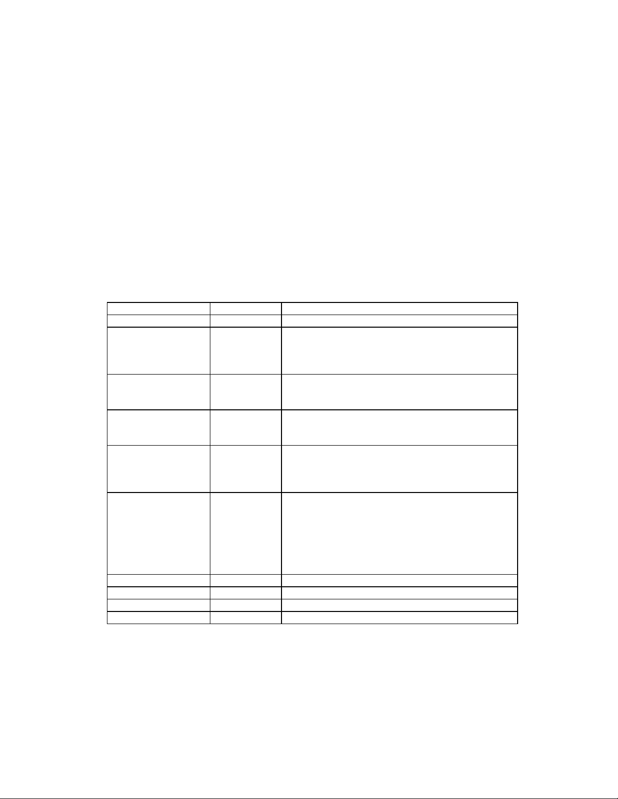
REVISIONS
Rev Number Date Notes
1 1989 Initial Release
2 22 Oct 99 Formatted manual; Added IEC requirements to
Specifications; Changed values in Specifications;
Clarified Connector information; Added correct
drawings; Clarified Card Present Signal
3 14 Sep 00 Section 1, Specs Corrected length dimension to
101.6 mm. Written to SI, International System of
Units.
4 25 Jul 01 Front Matter: Added to Agency page: FCC Class
B, UL and CUL, CE Class B. Copyright 2001
added.
5 08 Apr 03 Front Matter: added ISO line to logo, changed
Tech Support phone number, added new
warranty, changed warranty from 90 days to 1
year.
6 16 Jul 03 Sec 1: added cable length to Configuration Table
and deleted P/N 21050149 and added 21050005,
added MTBF Electronics to Specification Table,
changed power requirements to 2.7 VDC, and
corrected units. Table 2-1, 2-2, and 2-3 added
mating connectors and changed V
2.7. Table 2-1 corrected color-coding for pin 6.
from 2.4 to
cc
ii
Page 3

LIMITED WARRANTY
MagTek warrants that the products sold to Reseller pursuant to this Agreement will perform in accordance with
MagTek’s published specifications. This warranty shall be provided only for a period of one year from the date
of the shipment of the product from MagTek (the “Warranty Period”). This warranty shall apply only to the
original purchaser unless the buyer is authorized by MagTek to resell the products, in which event, this warranty
shall apply only to the first repurchase.
During the Warranty Period, should this product fail to conform to MagTek’s specifications, MagTek will, at its
option, repair or replace this product at no additional charge except as set forth below. Repair parts and
replacement products will be furnished on an exchange basis and will be either reconditioned or new. All replaced
parts and products become the property of MagTek. This limited warranty does not include service to repair
damage to the product resulting from accident, disaster, unreasonable use, misuse, abuse, customer’s negligence,
Reseller’s negligence, or non-MagTek modification of the product. MagTek reserves the right to examine the
alleged defective goods to determine whether the warranty is applicable.
Without limiting the generality of the foregoing, MagTek specifically disclaims any liability or warranty for
goods resold in other than MagTek’s original packages, and for goods modified, altered, or treated by customers.
Service may be obtained by delivering the product during the warranty period to MagTek (1710 Apollo Court,
Seal Beach, CA 90740). If this product is delivered by mail or by an equivalent shipping carrier, the customer
agrees to insure the product or assume the risk of loss or damage in transit, to prepay shipping charges to the
warranty service location and to use the original shipping container or equivalent. MagTek will return the product,
prepaid, via a three (3) day shipping service. A Return Material Authorization (RMA) number must accompany
all returns.
MAGTEK MAKES NO OTHER WARRANTY, EXPRESS OR IMPLIED, AND MAGTEK DISCLAIMS ANY
WARRANTY OF ANY OTHER KIND, INCLUDING ANY WARRANTY OF MERCHANTABILITY OR
FITNESS FOR A PARTICULAR PURPOSE.
EACH PURCHASER UNDERSTANDS THAT THE MAGTEK PRODUCT IS OFFERED AS IS. IF THIS
PRODUCT DOES NOT CONFORM TO MAGTEK’S SPECIFICATIONS, THE SOLE REMEDY SHALL BE
REPAIR OR REPLACEMENT AS PROVIDED ABOVE. MAGTEK’S LIABILITY, IF ANY, TO RESELLER
OR TO RESELLER’S CUSTOMERS, SHALL IN NO EVENT EXCEED THE TOTAL AMOUNT PAID TO
MAGTEK BY RESELLER UNDER THIS AGREEMENT. IN NO EVENT WILL MAGTEK BE LIABLE TO
THE RESELLER OR THE RESELLER’S CUSTOMER FOR ANY DAMAGES, INCLUDING ANY LOST
PROFITS, LOST SAVINGS OR OTHER INCIDENTAL OR CONSEQUENTIAL DAMAGES ARISING OUT
OF THE USE OF OR INABILITY TO USE SUCH PRODUCT, EVEN IF MAGTEK HAS BEEN ADVISED OF
THE POSSIBILITY OF SUCH DAMAGES, OR FOR ANY CLAIM BY ANY OTHER PARTY.
LIMITATION ON LIABILITY
EXCEPT AS PROVIDED IN THE SECTIONS RELATING TO MAGTEK’S LIMITED WARRANTY,
MAGTEK’S LIABILITY UNDER THIS AGREEMENT IS LIMITED TO THE CONTRACT PRICE OF THE
PRODUCTS.
MAGTEK MAKES NO OTHER WARRANTIES WITH RESPECT TO THE PRODUCTS, EXPRESSED OR
IMPLIED, EXCEPT AS MAY BE STATED IN THIS AGREEMENT, AND MAGTEK DISCLAIMS ANY
IMPLIED WARRANTY, INCLUDING WITHOUT LIMITATION ANY IMPLIED WARRANTY OF
MERCHANTABILITY OR FITNESS FOR A PARTICULAR PURPOSE.
MAGTEK SHALL NOT BE LIABLE FOR CONTINGENT, INCIDENTAL, OR CONSEQUENTIAL
DAMAGES TO PERSONS OR PROPERTY. MAGTEK FURTHER LIMITS ITS LIABILITY OF ANY KIND
WITH RESPECT TO THE PRODUCTS, INCLUDING ANY NEGLIGENCE ON ITS PART, TO THE
CONTRACT PRICE FOR THE GOODS.
MAGTEK’S SOLE LIABILITY AND BUYER’S EXCLUSIVE REMEDIES ARE STATED IN THIS SECTION
AND IN THE SECTION RELATING TO MAGTEK’S LIMITED WARRANTY.
iii
Page 4

FCC WARNING STATEMENT
This equipment has been tested and found to comply with the limits for Class B digital device, pursuant to Part 15
of FCC Rules. These limits are designed to provide reasonable protection against harmful interference when the
equipment is operated in a residential environment. This equipment generates, uses, and can radiate radio
frequency energy and, if not installed and used in accordance with the instruction manual, may cause harmful
interference to radio communications. However, there is no guarantee that interference will not occur in a
particular installation.
FCC COMPLIANCE STATEMENT
This device complies with Part 15 Of The FCC Rules. Operation of this device is subject to the following two
conditions: (1) This device may not cause harmful interference. And (2) This device must accept any interference
received, including interference that may cause undesired operation.
CANADIAN DOC STATEMENT
This digital apparatus does not exceed the Class B limits for radio noise for digital apparatus set out in the Radio
Interference Regulations of the Canadian Department of Communications.
Le présent appareil numérique n’émet pas de bruits radioélectriques dépassant les limites applicables aux
appareils numériques de las classe B prescrites dans le Réglement sur le brouillage radioélectrique édicté par les
ministère des Communications du Canada.
CE STANDARDS
Testing for compliance to CE and FCC requirements was performed by an independent laboratory. The unit
under test was found compliant to Class B.
UL/CSA
This product is recognized per Underwriter Laboratories and Canadian Underwriter Laboratories 1950.
iv
Page 5

TABLE OF CONTENTS
SECTION 1. FEATURES AND SPECIFICATIONS.....................................................................................1
CONFIGURATIONS .................................................................................................................................1
REFERENCE DOCUMENT......................................................................................................................1
SPECIFICATIONS....................................................................................................................................2
SECTION 2. INSTALLATION......................................................................................................................3
MOUNTING ..............................................................................................................................................3
CONNECTORS ........................................................................................................................................5
TIMING......................................................................................................................................................6
DATA.........................................................................................................................................................7
STROBE ...................................................................................................................................................7
CARD PRESENT......................................................................................................................................7
FIGURES
Figure 1-1. 101-millimeter Compatible Swipe Reader ------------------------------------------------------------------vi
Figure 2-1. Reader Mounting Dimensions With Cover------------------------------------------------------------------ 3
Figure 2-2. Reader Mounting Dimensions Without Cover ------------------------------------------------------------- 4
Figure 2-3. Timing --------------------------------------------------------------------------------------------------------------- 6
TABLES
Table 2-1. I/O Connector for Single Track, 6 Pin------------------------------------------------------------------------- 5
Table 2-2. I/O Connector for Dual Track, 8 Pin--------------------------------------------------------------------------- 5
Table 2-3. I/O Connector for 3 Track, 10 Pin------------------------------------------------------------------------------ 6
v
Page 6

Figure 1-1. 101-millimeter Compatible Swipe Reader
vi
Page 7

SECTION 1. FEATURES AND SPECIFICATIONS
The 101-millimeter OEM Swipe Reader has a TTL level interface and is designed for use in
retail, access control, and time and attendance environments. This Reader is in compliance with
industry specifications, including ANSI/ISO Standards 7810, 7811-1 through -6, 7812, 7813, and
AAMVA. The Reader can be customized. Bidirectional read capability is available.
CONFIGURATIONS
Part Number Read Color Cable Length
Integral Electronics,
Single Track with Cover
Integral Electronics,
Single Track without Cover
Integral Electronics,
Dual Tracks with Cover
Dual Tracks with Cover
Integral Electronics,
3 Tracks with Cover
REFERENCE DOCUMENT
I/O Interface for TTL Swipe Readers, Technical Reference Manual, P/N 99875148
21050001
21050002
21050003
21050058
21050057
21050004
21050005
21050145 Tracks 1,2, & 3 Black 20”
Track 1
Track 2
Track 3
Track 1
Track 2
Tracks 1 & 2
Tracks 2 & 3
Black
Black
Black
Black
Black
Black
Black
20”
20”
20”
7”
21”
20”
20”
1
Page 8

101-Millimeter Compatible Swipe Reader
SPECIFICATIONS
IEC:
Meets or Exceeds
Requirements for:
Flammability Meets UL94V-0
Recording Method Two-Frequency Coherent Phase (F2F)
Speed Card speed through the unit may vary from:
Power Requirements Single Track: 2.7 to 5.5Vdc at 1 mA, typical
Output Signal Levels Vol = 0.4 VDC at 2 mA
Operating Temperature -30 oC to 70 o C
Operating Humidity 10% to 90% relative humidity
Life 300,000 passes Single Track
MTBF Electronics 125,000 h
Dimensions Length: 4.0" (101.6 mm)
Cable Length,
Standard:
Connector See Section 2, Connectors
Colors available Black, Standard
IEC 1000-4-2 ESD (Electro Static Discharge)
IEC 1000-4-3 Radiated EMC Field (2X requirement)
IEC 1000-4-4 Electrical Fast Transient Burst requirement
(transmission on I/O cable)
2 to 125 in/s at 75 bpi (5.1 to 318 cm/s at 29.5 b/cm)
2 to 60 in/s at 210 bpi (5.1 to 152.4 cm/s at 82.7b/cm)
Dual Track: 2.7 to 5.5Vdc at 2 mA, typical
3 Tracks: 2.7 to 5.5Vdc at 3 mA, typical
V
= Vcc -0.5 VDC at -2 mA
oh
1,000,000 passes Multi-Track
Height: 1.08" (27.4 mm)
Width: 1.62" (41.1 mm)
Single Track: 20" (508.0 mm)
Dual Track: 20" (508.0 mm)
3 Track 20" (508.0 mm)
Consult Factory for other lengths
Pearl White Available
2
Page 9

SECTION 2. INSTALLATION
This section consists of installation and checkout of the Reader.
MOUNTING
The dimensions for mounting with the cover are shown in Figure 2-1.
Figure 2-1. Reader Mounting Dimensions With Cover
3
Page 10

101-Millimeter Compatible Swipe Reader
The dimensions for mounting without the cover are shown in Figure 2-2.
Figure 2-2. Reader Mounting Dimensions Without Cover
4
Page 11

Section 2. Installation
CONNECTORS
Single Track I/O Connector is shown in Table 2-1, and the Dual Track I/O Connector is shown
in Table 2-2.
Table 2-1. I/O Connector for Single Track, 6 Pin
Pin Number Color Signal
Connector for Single Track, 6 Pin 1 Yellow DATA
2 Orange CARD PRESENT
Molex 6 Pin 3 Green STROBE
22-01-2061 4
0.100 inch Contact Spacing 5 Red Vcc
Mates to Molex 22-05-2061 6 Brown GND
Note: Vcc = 2.7 to 5.5 VDC
Connector for Dual Track, 8 Pin 1 Yellow DATA (Tk 2)
2 White CARD PRESENT
3 Green STROBE (Tk 2)
Molex 8 Pin 4
22-01-2081 5 Red Vcc
0.100 inch Contact Spacing 6 Black GND
7 Blue STROBE (Tk 1 or Tk 3)
Mates to Molex 22-05-2081 8 Brown DATA (Tk 1 or Tk 3)
Note: Vcc = 2.7 to 5.5 VDC
−
KEY
Table 2-2. I/O Connector for Dual Track, 8 Pin
Pin Number Color Signal
−
KEY
5
Page 12
101-Millimeter Compatible Swipe Reader
Table 2-3. I/O Connector for 3 Track, 10 Pin
Connector for 3 Track, 10 Pin 1 Yellow DATA (Tk 2)
2 White CARD PRESENT
3 Green STROBE (Tk 2)
4 KEY
5 Red Vcc
Molex 10 Pin 6 Black GND
22-01-2101 7 Blue STROBE (Tk 1)
0.100 inch Contact Spacing 8 Brown DATA (Tk 1)
Mates to Molex 22-05-2101 9 Gray STROBE (Tk 3)
10 Orange DATA (Tk 3)
Pin Number Color Signal
Note: Vcc = 2.7 to 5.5 VDC
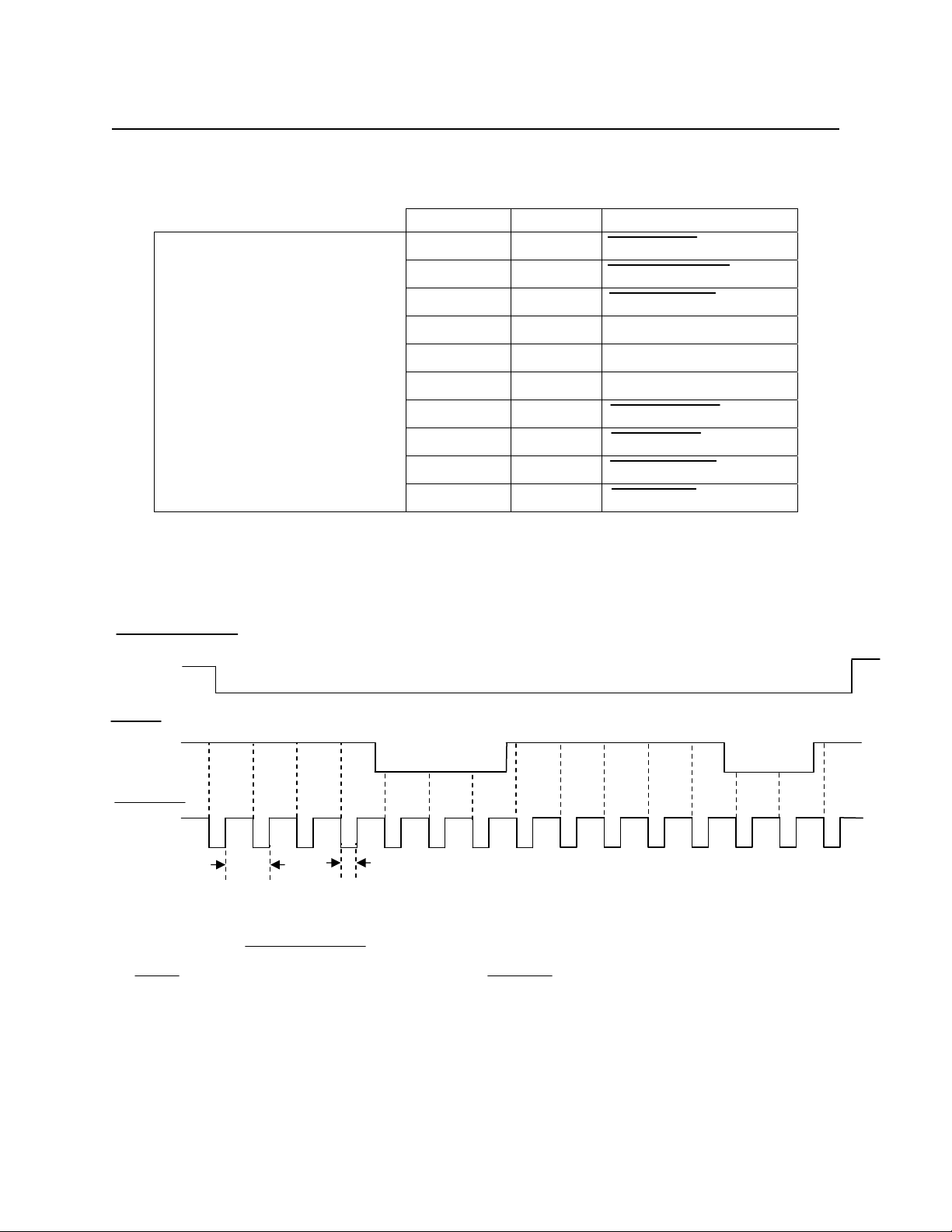
TIMING
CARD PRESENT
DATA
0 0 0 0
1 1 1 0 0 0 0 0 1 1 0
STROBE
Bit
Time
STROBE WIDTH APPROXIMATELY
25-50% OF BIT TIME
Notes:
1. Time out of the CARD PRESENT signal occurs approximately 150 ms after the last strobe transition.
2. DATA is valid 1.0μ sec before the negative edge of STROBE.
Figure 2-3. Timing
6
Page 13

Section 2. Installation
DATA
The Data signal is valid while the strobe is low. If the Data signal is high, the bit is a zero. If the
Data signal is low, the bit is a one.
STROBE
The Strobe signal indicates when Data is valid. It is recommended that Data be loaded by the
user with the leading edge (negative) of the Strobe.
CARD PRESENT
Card Present will go low after 14/15 flux reversals from the head. Card Present will return high
150 milliseconds after the last flux reversal.
When no card is being moved through the unit, the Data, Strobe, and Card Present signals are
high. The signal timing diagram shown above represents the data along with other signals that
are generated during the reading process.
7
Page 14

101-Millimeter Compatible Swipe Reader
8
 Loading...