

Magpowr PS90 Instruction Manuals
222 W. Memorial Road, Oklahoma City, OK 73126-0508
Phone: 1-800-624-7697 Fax: 405-755-8425
www.magpowr.com E-mail: magpowr@magpowr.com
INSTRUCTION MANUAL
MODEL PS90
90 VDC POWER SUPPLY
All of the information herein is the exclusive proprietary property of Maxcess International, and is disclosed with the
understanding that it will be retained in confidence and will neither be duplicated nor copied in whole or in part nor
be used for any purpose other than for which disclosed.
Copyright 2004, all rights reserved.
Periodically there will be updates to this manual. The latest version is available at www.magpowr.com or by calling
1-800-MAGPOWR (624-7697).
1.0 Introduction
The MAGPOWR Model PS90 is an isolated controllable current regulator for 90 vdc magnetic particle clutches and
brakes. The PS90 also provides a small amount of reverse current to minimize the drag torque of the clutch / brake.
The Model PS90 has four jumper selectable current ranges. Maximum outputs for the individual ranges are 0.125,
0.25, 0.5 and 1.0 adc. The appropriate range is determined by the current rating of the clutch or brake to be
controlled. For best torque control resolution, the lowest current range providing sufficient current for maximum
operating torque should be selected.
The PS90 accepts either a remote adjustment potentiometer, or a 0 to 10 vdc analog control signal.
Connections are provided for an external 1 madc current meter. The meter display will indicate output current as a
percentage of the output range selected.
The control circuits are electrically isolated from the power circuits.
2.0 Installation
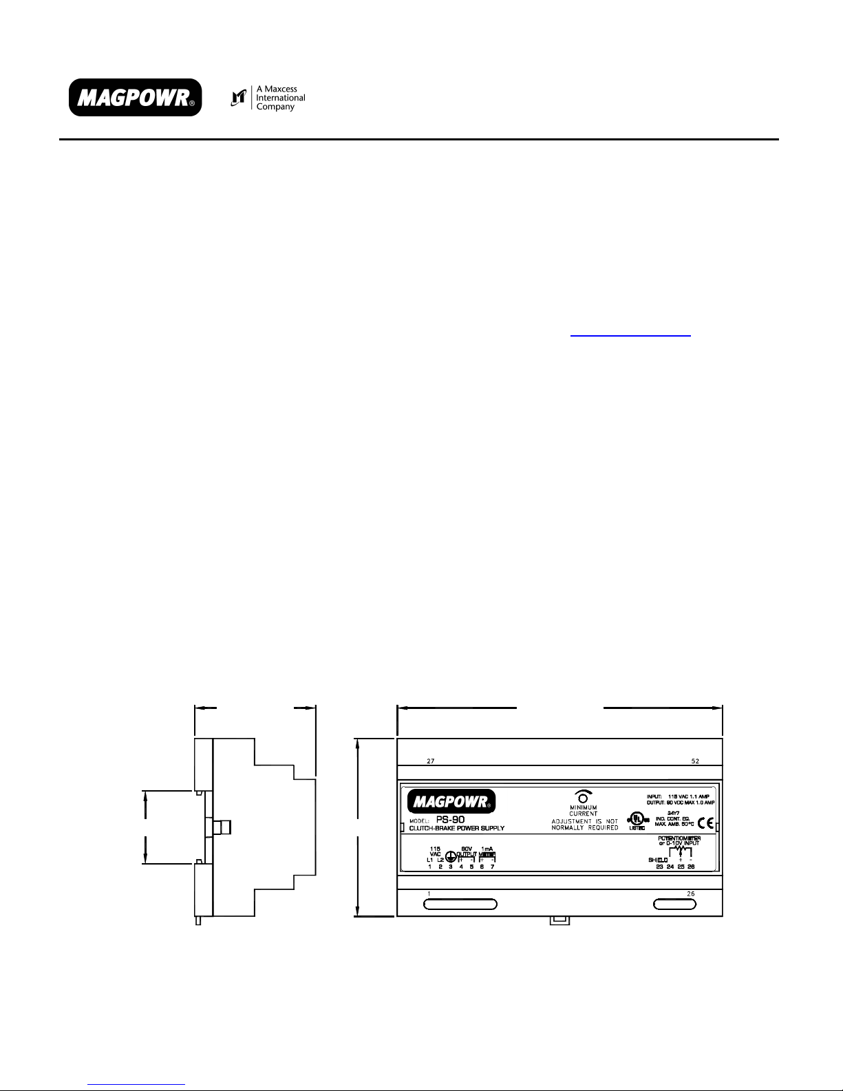
The PS90 is intended for installation on a vertical panel with a DIN 35 rail, with the wiring terminals facing down.
Figure 1 shows the enclosure dimensions.
1.39 [35.2 mm] 3.38 [85.9 mm]
Figure 1
Enclosure Dimensions
850A264-1
10/04 Rev. C
6.18 [157.0 mm]2.30 [58.4 mm]
Wiring to and from the PS90 must be done with double or reinforced insulation or protective screening which
provides protective separation. All wiring should comply with the essential requirements of the appropriate
standard(s) and is the responsibility of the installer.
Route AC power away from control signal wiring. Connect shields of shielded cable to the terminals indicated as
“SHIELD”. Maximum shield length and maximum length of wires outside of the shield is 3 in. (75 mm).
3.0 Setup
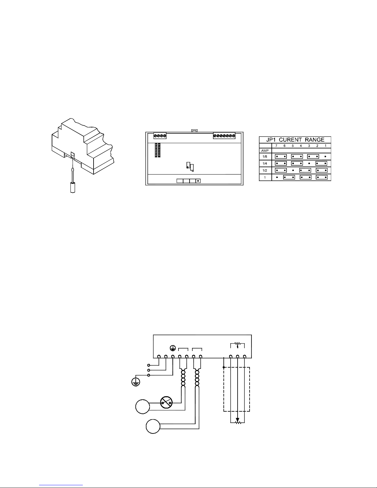
Remove the enclosure top by inserting a flat blade screwdriver under the retaining tabs in the base (See figure 2).
Set the JP1 current range selection jumpers to the range appropriate for the clutch / brake connected to the PS90
(See figure 3 for current range settings). The factory setting is 1/8 amp range. Replace the enclosure top.
71
JP1
Figure 2 Figure 3
Enclosure Top Removal JP1 Current Range Settings
4.0 Electrical Connections
Figure 4 shows the connections that are required for the basic system. They are:
115 vac power
90 vdc output for clutch / brake
1 to 10 kohm Potentiometer
Route AC power away from control wiring. The clutch / brake wires and the remote meter wires should be twisted
pair. Run the signal input wiring in shielded cable. Connect the shield to the provided terminal marked “SHIELD”.
The maximum shield length and maximum length of wires outside of the shield is 3 in. (75 mm).
When using a 0-10 vdc input instead of a potentiometer, connect the negative of the input to terminal 26 and the
positive of the input to terminal 25.
The 90 vdc output and the remote meter output are not isolated from the AC line and must not be ground
referenced. The potentiometer input is isolated and may be ground referenced.
POTENTIOMETER
L2
90V 1mA
OUTPUT METER
+-
-+
115
VAC
L1
1234567 23
SHIELD
or 0-10V INPUT
+
25 26
24
-
CLUTCH/
BRAKE
REMOT E
0-1 mA DC
(OPTIONAL)
2
115 VAC
50/60 Hz
SWITCH NOT
ALLOWED IN
D.C. OUTPUT
METER
Figure 4
Electrical Connections for PS90
CW
1K TO 10K
REMOTE POTENTIOMETER
 Loading...