


Installation instructions for:
89-89-65-005 Rev F
INTERCOOLED SUPERCHARGER SYSTEM
2005-2007
FORD MUSTANG 4.6L 3V
Step-by-step instructions for installing the best in supercharger systems.
PREMIUM FUEL REQUIRED
ATTENTION!
our MAGNA CHARGER intercooler kit
Is sensitive to corrosion!
Take care of if by using 50/50
Anti-freeze with de-ionized water.
Magnuson Products Inc
1990 Knoll Drive, Ventura, CA. 93003
Phone (805) 289-0044 * Fax (805) 677-4897
magnusonproducts.com * magnacharger.com

INSTALLATION MANUAL
9/07
Page 2
2005-2007 Ford Mustang Supercharger Installation Instructions
magnacharger.com
Magna Charger
FORD 4.8 Liter 3V Engine,
2005-2007 MUSTANG
Please take a few moments to review this manual thoroughly before you begin work:
A quick parts check to make certain your kit is complete (See shipper parts list in this package). If you discover shipping
damage or shortage, please call our offi ce immediately. Take a look at exactly what you are going to need in terms of
tools, time, and experience. Review our limited warranty with care. When unpacking the supercharger kit DO NOT lift
the supercharger assembly by the black plastic bypass actuator. This is pre-set from the factory and can be altered if
used as a lifting point!
Caution: Relieve the fuel system pressure before servicing fuel system components in order to reduce the risk of fi re
and personal injury . After relieving the system pressure, a small amount of fuel may be released when servicing the fuel
lines or connections. In order to reduce the risk of personal injury, cover the regulator and fuel line fi ttings with a shop
towel before disconnecting. This will catch any fuel that may leak out. Place the towel in an approved container when
the job is complete.
Use only premium fuel, 91 octane or better.
Magna Charger systems are manufactured to produce about 20 RWHP per pound of boost at sea level. High altitudes
will produce different numbers.
Our Magna Charger kits are designed for engines in good mechanical condition only. Installation on high mileage or
damaged engines is not recommended and may result in engine failure, for which we are not responsible. Magna Charger is not responsible for the engine or consequential damages.
Aftermarket engine re-calibration devices that modify fuel and spark curve (including, but not limited to programmers)
are not recommended and may cause engine damage or failure. Use of non-Magna Charger approved programming
will void all warranties. If you have any questions, call us.
After you fi nish your installation and road test your vehicle, please fi ll out and mail in the limited warranty card, so we
can add you to our fi les (this is important for your protection).
• A new fuel fi lter is recommended at the time of supercharger installation.
• Stock application Motorcraft spark plugs are recommended
• Drive belt= Gates# K061247
• Air Filter= K&N# 33-2298
Tools Required:
Metric wrench set
¼” - 3/8” and ½” drive metric socket set (Standard & Deep)
3/8” and ½” drive Foot pound and inch pound torque wrenches
Phillips and fl at head screwdrivers
Fuel line quick disconnect tools (included in kit)
Small or angled 3/8” drill motor
Drain pan
Hose cutters
Hose clamp pliers
Safety glasses
Metric Allen socket set 3/8” drive
Electric drill and drill bits
Contact Information:
Magnuson Products Inc
Magna Charger Division
1990 Knoll Drive
Ventura, CA, 93003
Sale/Tech Support (805) 289-0044
Web site:
www.magnusonproducts.com
www.magnacharger.com
E-mail:
info@magnacharger.com

1. Relieve the pressure in the fuel tank by
9/07
Page 3
2005-2007 Ford Mustang Supercharger Installation Instructions
magnacharger.com
removing the cap and re-installing it.
IMPORTANT! Ensure vehicle has
91 or higher-octane fuel in it prior to
supercharger installation!
2. Disconnect the negative (-) battery
clamp using a 7mm wrench.
3. Remove the Positive Crankcase
Ventilation (PCV) line from the air tube
by pressing the release trigger in the
connector and pulling it free. Follow the
line to its connection on the cam cover
and remove the line completely from the
motor.
4. Loosen the air tube clamp at the throttle
body using a 8mm nut driver or straight
blade screwdriver.
Release Trigger

5. Loosen the air tube clamp at the air box
9/07
Page 4
2005-2007 Ford Mustang Supercharger Installation Instructions
magnacharger.com
using a 8mm nut driver or straight blade
screwdriver
6. Remove the air tube completely from the
vehicle.
7. Remove the Throttle Position Switch
(TPS) connector by sliding the red
release latch outward and pulling the
connector free.
8. Remove the Electronic Throttle Control
(ETC) connector by sliding the red
release latch outward and pulling the
connector free.
Release Latch
Release Latch

9. Disconnect the (8) fuel injector
9/07
Page 5
2005-2007 Ford Mustang Supercharger Installation Instructions
magnacharger.com
connectors by squeezing the release
trigger and pulling the connectors free.
10. Remove the Fuel Pressure Sensor
(FPS) connector by squeezing
the release trigger and pulling the
connectors free.
Release Trigger
Release Trigger
11. Remove the vacuum line to the FPS.
12. Remove the (2) battery cable anchors
by pulling them free from the fuel rail
attachment bolts.

13. Remove the Evaporative Control (EVAP)
9/07
Page 6
2005-2007 Ford Mustang Supercharger Installation Instructions
magnacharger.com
line behind the throttle body by pressing
in on the white release latch and pulling
the line free.
14. Remove the PCV line from the intake
manifold by pressing the release
trigger in the connector and pulling it
free. Follow the line to its connection
on the cam cover and remove the line
completely from the motor.
Release Latch
15. Remove the fuel line lock clip from the
fuel rail by gently prying it free.
16. Use the supplied tool to remove the
fuel line from the fuel rail. CAUTION!
WEAR EYE PROTECTION! The fuel
line will be under pressure. Extinguish
any open fl ame or source of ignition.
Snap the tool on to the fuel rail in place
of the lock clip. Push the tool towards
the fuel line while pushing the line
towards the tool. Pull back on the line
and it will come free. Use a clean shop
towel to collect any spilled fuel.
Fuel Line Lock Clip
Fuel Line Removal Tool

17. Remove the (4) bolts that secure the fuel
9/07
Page 7
2005-2007 Ford Mustang Supercharger Installation Instructions
magnacharger.com
rails to the intake manifold using a deep
8mm socket wrench.
18. Remove the fuel rails complete with
injectors from the intake manifold, by
pulling up fi rmly on the fuel rails.
19. At the rear of the intake manifold locate
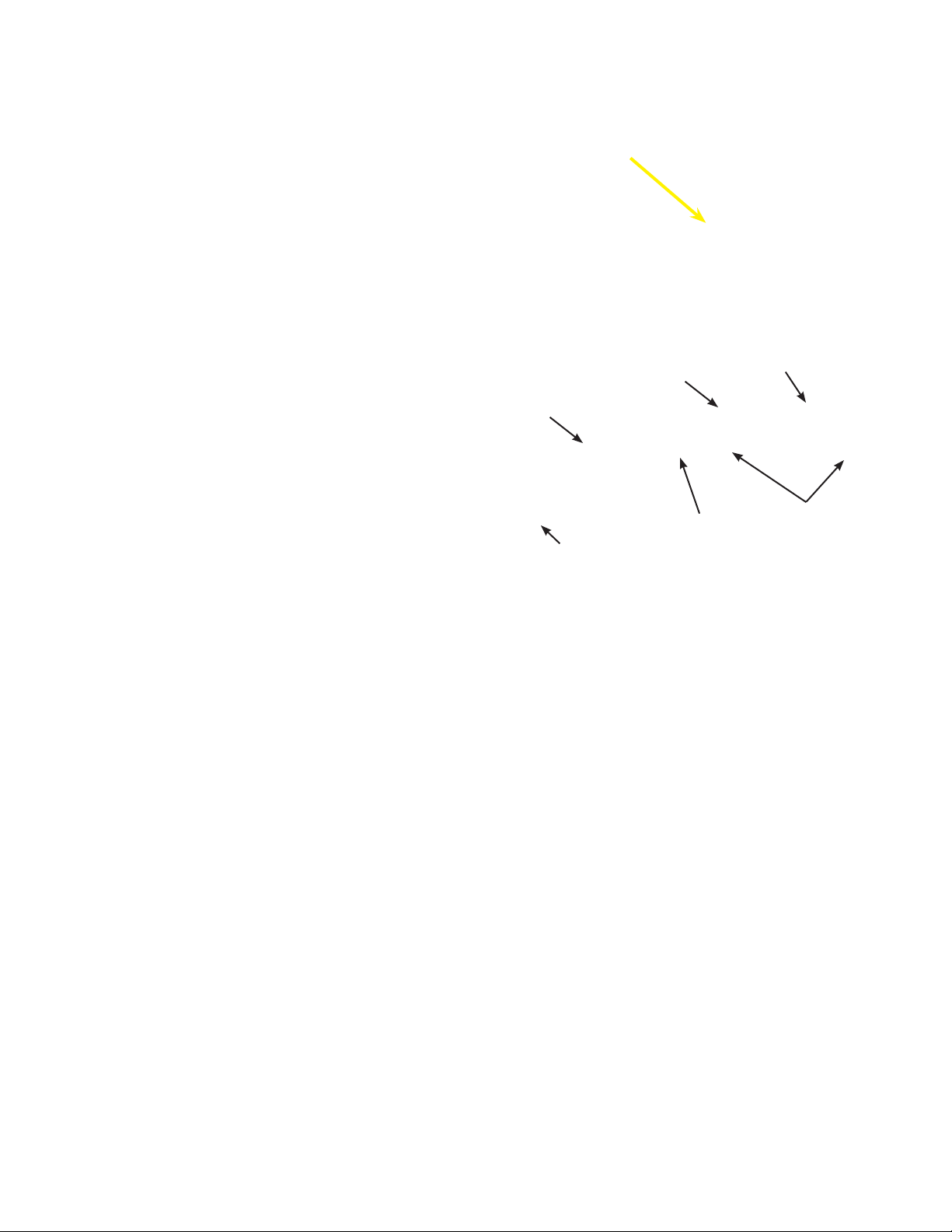
the electrical connector for the manifold
servo- motor.
20. Press the release trigger and pull the
connector apart.
Release Trigger

21. At the rear of the intake manifold remove
9/07
Page 8
2005-2007 Ford Mustang Supercharger Installation Instructions
magnacharger.com
the brake vacuum hose by squeezing
the ears of the clamp using a pair of
pliers and pulling the hose free.
22. Remove the (5) bolts on each side of the
intake manifold using a 10mm socket
wrench.
Brake Vacuum Hose
23. Carefully lift the intake manifold free
from the engine.
24. Carefully clean the cylinder head port
faces and cover them with masking tape
or clean shop towels.

25. Depress the tensioner arm by inserting
9/07
Page 9
2005-2007 Ford Mustang Supercharger Installation Instructions
magnacharger.com
the square end of a 1/2” breaker bar into
the square hole on the arm. Press the
bar down to relieve tension on the belt
and remove the belt from the pulleys.
This belt will no longer be used.
26. Remove the Alternator bracket and the
(4) bolts that secure it in place using a
10mm socket wrench
1/2” Breaker Bar
27. Remove the (2) nuts that secure the
alternator using a 13mm wrench.
28. Lift the alternator up off its mounting
studs and carefully place it on the
passenger side fender well. Protect the
fender wall using a thick shop towel or
fender cover.
Remove Nuts

29. Remove the (2) alternator-mounting
9/07
Page 10
2005-2007 Ford Mustang Supercharger Installation Instructions
magnacharger.com
studs by placing a 6mm socket wrench
on the hex ends of the studs or “doublenutting” them and unscrewing them from
the engine block.
30. The following steps are for Intercooled
vehicles only! Non-intercooled vehicles
please skip to step 58.
On the passenger side of the vehicle,
under the nose, locate the white plastic
radiator drain valve. Open the valve and
collect the coolant in a drain pan for reuse late in the installation.
Remove Studs
Double Nutted Stud
31. Remove the coolant hoses from the
coolant manifold. Use a pair of pliers to
squeeze the clamps that secure them.
Pull both hoses free from the coolant
manifold. Also remove the passenger
side coolant hose from where it meets
the radiator and set this hose aside for
future modifi cations.
32. On the bottom of the coolant manifold, in
the engine valley, locate the heater hose
connector. Squeeze the (2) gray release
latches and pull the connector free from
the steel “elbow”.
Radiator Drain Valve
Coolant Hoses and Clamps
Release Latches
Pull

33. Remove the gray release latches from
9/07
Page 11
2005-2007 Ford Mustang Supercharger Installation Instructions
magnacharger.com
the elbow and insert them into the
connector.
34. Remove the coolant manifold and the (4)
bolts that secure it using a 10mm socket
wrench.
35. Grasp the steel elbow on the bottom of
the coolant manifold using a large set of
pliers. Using a small torch or heat gun,
apply heat to the bottom of the manifold
were the steel elbow is inserted.
36. Pull the elbow free from the manifold,
but do not twist it, as this will damage
the aluminum manifold.
Steel Elbow
Torch or Heat Gun
HEAT
Pull

37. Allow the manifold to cool completely.
9/07
Page 12
2005-2007 Ford Mustang Supercharger Installation Instructions
magnacharger.com
Install the small 5/8” core plug supplied
using a suitable drift and hammer in to
the hole that the elbow was removed
from.
38. Here is the core plug correctly installed
in the bottom of the coolant manifold.
39. Locate the Engine Coolant Temperature
(ECT) connector clipped to the steel
coolant pipes in the engine valley.
Disconnect it by squeezing the release
trigger of the connector and pulling it
apart.
40. Locate the Engine Knock Sensor (EKS)
connector clipped to the steel coolant
pipes. Disconnect it by squeezing the
release trigger of the connector and
pulling it apart.

41. At the rear of the passenger side
9/07
Page 13
2005-2007 Ford Mustang Supercharger Installation Instructions
magnacharger.com
cylinder head, locate the bolt that secure
the steel coolant pipes in place and
remove it using a 13mm socket wrench.
42. Pull the coolant pipes up so you can
remove the coolant hoses and clamps
using a pair of pliers.
43. After removing the coolant hoses, gently
lift the pipes up and back to remove
them from the engine. Some additional
engine coolant will be lost at this point,
place a suitable drain pan under the
transmission bellhousing to collect it.
44. When removing the steel coolant
pipes from the engine, take care not
to damage the smaller of the (2) pipes
and the nipple where it connects to the
engine block. The coolant pipe is a “slipfi t” on this nipple.
Engine Block Nipple
Coolant Pipe

45. Place the coolant pipes in the soft jaws
Engine Block Nipple
9/07
Page 14
2005-2007 Ford Mustang Supercharger Installation Instructions
magnacharger.com
of a vice. Separate the (2) coolant pipes
by cutting the connecting brackets using
a hack saw.
46. Use care when cutting, as the smaller
diameter pipe will be re-used.
Cut Here
47. Here are the coolant pipes separated,
and the smaller diameter pipe is now
ready for re-installation.
48. Re-install the smaller diameter coolant
pipe by fi rst carefully starting the end
on the engine block nipple. Secure the
coolant pipe with the bolt previously
removed. Re-connect the ECT and
EKS sensor connectors. Using some
of the ty-straps supplied, secure the
connectors to the coolant pipe and the
remaining portion of the connecting
bracket.
Engine Block Nipple
49. Re-install the coolant hose onto the pipe
9/07
Page 15
2005-2007 Ford Mustang Supercharger Installation Instructions
magnacharger.com
using the original clamp.
50. On to the remaining coolant hose, install
the 90-degree connector and the “elbow”
hose supplied as shown. Secure the
90-degree fi tting with the original clamp,
and the elbow hose with the new spring
clamp supplied.
51. Here is the 90-degree fi tting and elbow
hose installed. Route the long straight
section of the elbow hose forward along
the side of the engine to be connected in
a later step.
Coolant Hose
Spring Clamp
90º Fitting
“Elbow” Hose
52. Locate the passenger side coolant hose
removed previously. Note: Which end
goes to the manifold and to the radiator.
Just below the “dog leg” bend in the
middle of the hose, locate the short,
straight section and cut the hose in the
middle of this section.
To Manifold
Cut Here
To Radiator

53. Install the hose connector supplied into
9/07
Page 16
2005-2007 Ford Mustang Supercharger Installation Instructions
magnacharger.com
the ends of the hose. Note that the barb
on the connector will point rearwards,
towards the engine, away from the
radiator. Secure the connector in the
hose with the #18 clamps supplied but
leave them loose so fi nal adjustments
can be done on the vehicle.
54. Here is the completed hose with the
connector installed.
55. Re-install the water manifold. Torque
the fasteners to 89 in-lbs using a 10mm
socket and torque wrench.
To Manifold
To Radiator
56. Re-install both coolant hoses. Note, on
the passenger side hose, that the barb
on the connector will point rearwards
towards the engine, away from the
radiator. Secure the connector clamps
after the fi nal adjustments.
57. Install the end of the elbow hose on
9/07
Page 17
2005-2007 Ford Mustang Supercharger Installation Instructions
magnacharger.com
to the barb of the new coolant hose
connector with the spring clamp
supplied. Position the connector and
elbow hose so that the elbow hose can
be routed beside the engine. Tighten
the connector hose clamps. Refi ll
the radiator reservoir with the coolant
removed earlier.
Hose Connector Barb
Elbow Hose
58. Here is the new drive belt idler pulley
and mounting hardware.
59. Install the new bolts through the
bracket and into the holes that originally
mounted the alternator. Note, the gap
between the bracket and the block, this
is where the alternator will mount.
Idler Pulley Mounts Here
Pulley
Spacer
Idler Pulley Bolt
Bracket
Bracket Bolts
60. Install the alternator and torque the (2)
mounting bolts to 22 ft-lbs (30 Nm) using
a 12mm socket and torque wrench.

61. Install the idler pulley with its spacer
9/07
Page 18
2005-2007 Ford Mustang Supercharger Installation Instructions
magnacharger.com
into the remaining hole on the mounting
bracket with the bolt supplied. Torque
this bolt to 28 ft-lbs (38 Nm) using a
15mm socket and torque wrench.
62. Install the (2) new alternator brackets
with the (4) original bolts. Torque them
to 106 in-lbs (12Nm) using a 8mm and
10mm sockets and a torque wrench.
63. Remove the (3) bolts that secure the belt
tensioner using a 10mm socket wrench
and remove the tensioner from the front
of the motor.
64. Carefully place the tensioner in the soft
jaws of a vice. Using a hacksaw or a
small grinder, remove the center stop of
the tensioner.
Alternator
Brackets
Remove Stop As Shown

65. Here is the tensioner with the stop
9/07
Page 19
2005-2007 Ford Mustang Supercharger Installation Instructions
magnacharger.com
removed. Ensure that there is no
material left on the body of the tensioner
where the stop previously was. Grind or
fi le the body to make this area smooth
and fl at with the surrounding area of the
body.
66. Re-install the modifi ed tensioner into it
original location with its bolts. Torque
the (3) bolts to 22 ft-lbs (30 Nm) using a
10mm socket and torque wrench.
This area must
be fl at and
smooth.
Removed Stop
67. Remove the throttle body from the intake
manifold by removing the (2) bolts at the
top using a 8mm wrench. Remove the
nuts at the bottom of the throttle body
using a 10mm wrench.
68. With the (2) nuts removed in the last
step, tighten them against each other
“double-nutting” them on each stud.
Remove the (2) studs from the intake
manifold this way.
Mounting Nuts, “Double-Nutted”

69. Install the two-throttle body-mounting
9/07
Page 20
2005-2007 Ford Mustang Supercharger Installation Instructions
magnacharger.com
studs removed in the previous
step into the lower (2) holes on the
supercharger inlet fl ange. Double-nut
the studs, tighten them securely into the
supercharger inlet fl ange and remove
the nuts.
70. Carefully remove the throttle body
gasket from the intake manifold.
Double-Nutted Stud
71. Install the throttle body gasket into the
groove in the inlet manifold fl ange.
72. Install the throttle body onto the inlet
manifold with the TPS on the passenger
(right) side using the original bolts.
Tighten the (2) bolts and (2) nuts using 8
&10mm sockets and torque them to 106
in-lbs (12Nm).
Gasket

73. Carefully remove the (8) intake manifold
9/07
Page 21
2005-2007 Ford Mustang Supercharger Installation Instructions
magnacharger.com
gaskets from around the port openings
on the bottom of the intake manifold.
Gaskets
74. Clean and inspect the manifold gaskets
removed from the original intake
manifold. Install the gaskets onto the
supercharger manifold. Note, the “tab”
on the gasket and how it fi ts in the
slot provided for it. Ensure that all (8)
gaskets are installed correctly
75. Using a small amount of the grease
supplied, lubricate the fuel manifold Oring and install it into the recess on the
driver side fuel rail.
Gasket
Tab
76. Install the fuel manifold on to the driver
side fuel rail using supplied O-ring and
bolts. Torque the fuel manifold bolts to
106 in-lbs (12Nm) using a torque wrench
and 10mm socket. Be careful not to
pinch the O-ring.

77. Remove the FPS from the fuel rail by
9/07
Page 22
2005-2007 Ford Mustang Supercharger Installation Instructions
magnacharger.com
removing the (2) mounting bolts using a
8mm socket wrench.
78. Carefully install the FPS onto the fuel
manifold using a small amount of the
grease supplied on the sensor O-ring.
Fasten the sensor using the (2) original
mounting bolts. Torque the bolts using a
torque wrench and a 8mm socket to 106
in-lbs (12Nm).
Fuel Pressure Sensor
79. Connect (1) end of the 6” length of 1/4”
hose supplied to the small barb located
behind the bypass canister on the
supercharger manifold. Connect the
remaining end of the hose to the FPS
barb located on the fuel rail as shown.
80. Remove the tape or shop towels placed
over the port faces. With the help of an
assistant carefully set the supercharger
and manifold assembly in place. Do not
use the black plastic bypass canister as
a lifting point. This is pre-set from the
factory and can be damaged if you lift
with it.
Fuel Pressure Sensor

81. Install the 10 intake manifold bolts into
0
9/07
Page 23
2005-2007 Ford Mustang Supercharger Installation Instructions
magnacharger.com
place on the supercharger manifold.
Torque all manifold fasteners in (2) steps
using a 10mm socket and torque wrench
using the diagram shown in the next
step.
82. Torque all manifold fasteners in (2)
steps. In the fi rst step torque the
fasteners to 18 in-lbs (2Nm). In the
second step torque to 89 in-lbs (10Nm)
using the diagram shown.
83. Here is the new drive belt routing
diagram.
S/C
Alt.
Idlr
Idlr
W/P
Idlr
3.
P/S
Te n sr.
Idlr
Crank
A/C

84. Using a “breaker bar” or long 1/2” ratchet
9/07
Page 24
2005-2007 Ford Mustang Supercharger Installation Instructions
magnacharger.com
wrench, relieve the tension on the
tensioner arm and install the new drive
belt using the belt diagram provided.
85. Locate the Mass Air Flow (MAF)
connector on the wiring harness.
Remove the tape from tape form the
harness back to the main branch.
1/2” Breaker Bar
86. On the MAF connector, locate the
SOLID GRAY wire and the GRAY/RED
wire. This is the Intake Air Temp (IAT)
circuit.
87. Approximately (2) inches behind the
connector cut only the SOLID GRAY and
the GRAY/RED wires.

88. Remove the tape on the main branch
9/07
Page 25
2005-2007 Ford Mustang Supercharger Installation Instructions
magnacharger.com
of the wiring harness behind the MAF
connector backs to about the #6 fuel
injector branch. Locate the SOLID
GRAY and the GRAY/RED wires
previously cut from the MAF connector
and pull them free from the harness to
this point. You will be making a new
branch on the wiring harness with these
wires.
89. Tape the (2) short ends of the Gray and
Gray/Red wire at the MAF connector to
the harness as they will no longer be
used. Recover the harness with tape
leaving the SOLID GRAY and the GRAY/
RED wire exposed.
SOLID GRAY and GRAY/RED Wires
90. Install the new IAT connector harness
onto the Grey and the Gray/Red wires
using the crimp/shrink connectors
supplied. Either white wire can be
connected to the solid Grey and the
Gray/Red wire.
91. Install the crimp/shrink connectors by
stripping a 1/4” of insulation off each
end of the wires. Insert (1) end of the
wire into the crimp shrink connector
and crimp it securely. Using a heat gun
or blow dryer set on high, shrink the
plastic covering of the connector until
the plastic covering completely around
the wire. Crimping the connector alone
is not enough to ensure a permanent
connection; you must shrink the plastic
covering! When you are fi nished cover
the wires and connectors with the piece
of split loom supplied.
IAT Connector Harness

92. Install the new IAT sensor connector
9/07
Page 26
2005-2007 Ford Mustang Supercharger Installation Instructions
magnacharger.com
onto the IAT sensor located at the rear of
the supercharger manifold.
93. Install the ETC connector onto the
throttle body.
Intake Air Temperature Sensor
94. Install the TPS connector onto the
throttle body.
95. Install the fuel pressure connector to the
sensor on the fuel rail.

96. Install all eight-fuel injector connectors
9/07
Page 27
2005-2007 Ford Mustang Supercharger Installation Instructions
magnacharger.com
onto the injectors.
97. Remove the air box cover by pulling the
latches rearward and lifting up on the
cover. Remove the air fi lter element.
Note: A replacement element is supplied.
Pull
98. Remove the air box from the vehicle
by removing the mounting bolt using a
10mm socket wrench.
99. Carefully remove the MAF element from
the air box cover by removing the (2)
screws using a T-20 Torque driver.
Remove

100. Assemble the MAF element into the new
9/07
Page 28
2005-2007 Ford Mustang Supercharger Installation Instructions
magnacharger.com
air box cover with the original screws.
Note the direction of the “FLOW” as
shown on the MAF element-mounting
fl ange, this should point towards the
round opening of the new air box cover.
101. Here are the new air box cover latch
components. There are components for
(3) latch assemblies.
Threaded
Plate
MAF Element
Air Flow
Latch
Base
Plate
Mounting
Screws
102. Install the air box cover latches by
sliding the base plate into place on the
left (inlet) side of the air box. Push the
base plate up under the upper edge of
the box and against the side of the air
box mount. Note how the left side of the
base plate matches the contour of the air
box. Use a scribe or a pen to mark the
location of the holes in the base plate on
the side of the air box.
103. Use a 3/16” drill to make holes in the
locations you marked.
Push Up and Over, Mark Position

104. Install the latch into place by passing the
9/07
Page 29
2005-2007 Ford Mustang Supercharger Installation Instructions
magnacharger.com
mounting screws through the latch, base
plate and into air box
105. Install the threaded plate by threading
the mounting screws into it. Tighten the
screws securely. Note how the bottom
edge of the threaded plate matches the
contour of the air box.
106. Here is latch installed on the left side of
the air box.
107. Install another latch using the described
method on the rear of the air box as
shown. Ensure that the base plate is
pushed up under the upper edge of the
air box.

108. Finally install the last latch on the right
9/07
Page 30
2005-2007 Ford Mustang Supercharger Installation Instructions
magnacharger.com
side of the air box in the location shown.
109. Re-install the air fi lter element into the
air box.
110. Install the new air box cover by engaging
the (3) locating tabs on the rear of the air
box.
111. Position the air box cover in place as
shown and secure it by snapping the (3)
latches down.

112. Re-install the modifi ed air box assembly
9/07
Page 31
2005-2007 Ford Mustang Supercharger Installation Instructions
magnacharger.com
into its original location. Tighten the
mounting bolt securely using a 10mm
socket wrench.
113. Install the MAF connector onto the MAF
sensor.
114. Here is the air tube assembly and
mounting components.
115. Locate the original air tube assembly.
Inspect and squeeze the smaller, round
(MAF) end to see if there is a vapor
element installed. If your vehicle has
a vapor element it must be installed in
the supercharger system or SERIOUS
ENGINE DAMAGE WILL RESULT! If no
element is present please skip to step
119.
Squeeze this end to see if a Vapor
Element is present.

116. Remove the clamp from the end of the
9/07
Page 32
2005-2007 Ford Mustang Supercharger Installation Instructions
magnacharger.com
air tube. Use a sharp knife or razor
blade to cut the rubber of the air tube to
free the vapor element.
117. Carefully remove the vapor element from
the air tube.
Vapor Element
118. Install the vapor element into the end
of the new air tube as far as it will go.
Next, slide the new “hump” hose over
the element and onto the air tube.
119. Install the hose and clamps onto the
air tube as shown. Do not tighten the
clamps completely at this time.

120. Install the air tube assembly by sliding
9/07
Page 33
2005-2007 Ford Mustang Supercharger Installation Instructions
magnacharger.com
the round hose onto the air box cover
connection fi rst, then working the oval
hose onto the throttle body.
121. With the air tube assembly installed,
carefully tighten all (4) hose clamps.
Note: The PCV barb.
PCV Barb
122. Using a shop knife cut the plastic tubing
on the original PCV lines to free the
plastic end fi ttings.
123. Remove the brake vacuum hose where
it meets the check valve on the brake
booster. This hose, the “T” fi tting and
small hose connected to it will no longer
be used.
Check Valve

124. Cut a 2” length of 3/4” vapor line from
9/07
Page 34
2005-2007 Ford Mustang Supercharger Installation Instructions
magnacharger.com
the length of hose supplied.
125. Cut a 2-1/2” length of 3/8” fuel line from
the length of hose supplied.
2”
126. Cut the length of 11/32” vacuum hose
supplied into (2) pieces, (1) 7” long and
the other hose 17” long.
127. Here are the components that will make
up the driver side PCV/brake hose
assembly. Note: The 3/8” “T” fi tting
and the 3/4” to 3/8” adaptor fi ttings are
supplied.
7”
11/32 Vacuum Hose
3/8” Hose
2-1/2”
17”
“T” Fitting
Hose Adaptor
3/4” Hose
PCV Fitting

128. Here is the driver side PCV hose
9/07
Page 35
2005-2007 Ford Mustang Supercharger Installation Instructions
magnacharger.com
assembled.
129. Install the 90-degree PCV fi tting onto
the barb located on the driver side cam
cover.
130. Install the remaining end of the 11/32
vacuum hose on the barb to the brake
booster check valve.
131. Install the vacuum hose onto the
barb located on the driver side of the
supercharger inlet manifold.
11/32” Vacuum Hose
Check Valve
EVAP
Hose
Barb
Brake
Hose
Barb

132. Locate the EVAP hose previously
9/07
Page 36
2005-2007 Ford Mustang Supercharger Installation Instructions
magnacharger.com
removed. Connect the hose to the
upper barb on the supercharger inlet
manifold.
133. Connect the EVAP hose to the upper
barb located on the driver side of the
inlet manifold as shown.
EVAP
Hose
134. Remove the fi ttings from the end of the
passenger side PCV line.
135. Install the fi ttings removed in the last
step into the remaining length of the 3/8”
hose supplied.

To EVAP
To Cam
Arm Cover
Throttle
Body
Supercharger
S/C Intake
To Cam
Arm Cover
Front of
Vehicle
To Brake
Booster
Air Tube
136. Connect the end of the new PCV line
9/07
Page 37
2005-2007 Ford Mustang Supercharger Installation Instructions
magnacharger.com
to the passenger side cam cover barb.
Route the hose toward the front of the
vehicle.
137. Connect the remaining end of the new
PCV line to the barb on the side of the
new air tube assembly.
138. Here is a diagram of the hose routing.
139. Install the fuel line connector onto the
barb on the fuel manifold. Firmly push
the connector until you feel it snap into
place. Pull on fuel line to ensure it
cannot be removed.

140. Install the fuel line lock clip onto the fuel
9/07
Page 38
2005-2007 Ford Mustang Supercharger Installation Instructions
magnacharger.com
manifold. Ensure that the fuel line is
properly connected.
141. The following steps are for Intercooled
vehicles only! Non-intercooled vehicles
please skip to step 219. Remove the
(6) push-rivets that secure the radiator
shroud.
142. Remove the push-rivets by fi rst prying
up the center of the rivet using a small
straight blade screwdriver and the
remove the outer body of the rivet
complete.
143. Remove the radiator shroud.

144. Raise the vehicle on an approved lift or
9/07
Page 39
2005-2007 Ford Mustang Supercharger Installation Instructions
magnacharger.com
jackstands. Locate the (7) fasteners that
retain the lower splash shield.
145. Remove the (7) fasteners using a 6mm
socket wrench.
146. Remove the lower splash shield from the
vehicle.
147. In both of the front wheel wells remove
the (3) screws that secure the inner
plastic fender well using a crosshead
screwdriver.
Remove
Screws

148. In each of the front wheel wells remove
9/07
Page 40
2005-2007 Ford Mustang Supercharger Installation Instructions
magnacharger.com
the (3) push-rivets that secure the inner
plastic fender well. (Left front shown.)
149. Remove the push-rivets by pulling up on
the center portion and then removing the
complete rivet assembly as shown.
150. Between the grille and headlight on both
sides of the vehicle, remove the bolt on
the top of the fascia.
151. Carefully remove the front plastic fender
wells from both sides of the vehicle.
Note: Where the front fascia meets the
fender.
Remove
Fender
Fascia

152. On the inside of the fender where the
9/07
Page 41
2005-2007 Ford Mustang Supercharger Installation Instructions
magnacharger.com
fender meets the fascia, remove the (2)
nuts using a 10mm socket wrench. (The
fascia has been removed in this photo
for clarity.)
153. Carefully pull the fascia forward a few
inches to remove the fi nal connections.
Remove
154. With the front fascia pulled forward a few
inches, remove the fog light electrical
connectors by squeezing the release
triggers and pulling the connectors free.
The front fascia can now be completely
removed and set aside.
155. Remove the nut that secures the hornmounting bracket using a 10mm wrench.
Fog Light
Electrical
Connector
Remove Nut

156. Squeeze the trigger on the electrical
9/07
Page 42
2005-2007 Ford Mustang Supercharger Installation Instructions
magnacharger.com
connector to remove it from the horns.
Next, remove the horn from the original
mounting bracket using a 10mm wrench.
157. Using the original mounting nuts,
mount the horns onto the new horn
bracket supplied as shown. Tighten the
mounting nuts securely using a 10mm
wrench.
Remove Nuts
158. On the outside of the right (passenger
side) frame rail, directly behind the
bumper structure, make (2) 3/16” holes
using a drill in the locations shown.
159. Install the horn-mounting bracket onto
the frame using the (2) self-tapping bolts
supplied installed into the new holes.
Tighten the bolts securely using a 10mm
socket wrench.
7/8”
2-3/4”
3”

160. Here is the horn assembly installed.
9/07
Page 43
2005-2007 Ford Mustang Supercharger Installation Instructions
magnacharger.com
161. Install the horn electrical connector.
162. Mount the intercooler pump relay in the
location shown by passing a ty-strap
through the hole in its mounting tab
and through a hole in the upper cross
member.
163. Locate the ground connections on the
top surface of the upper cross member.
Relay

164. Remove the bolt from either ground
9/07
Page 44
2005-2007 Ford Mustang Supercharger Installation Instructions
magnacharger.com
connections using a 10mm wrench.
Pass the bolt through the ring connector
of the BLACK wire from the intercooler
relay. Tighten the bolt securely.
165. Locate the black plastic fuse holder in
the larger RED power wire. Install the
15-amp fuse supplied as shown, and
then snap the attached cover on the
fuse holder.
166. Remove the top cover of the fuse/relay
center.
167. Remove the bolt securing the battery
cable connector using a 10mm socket
wrench. Place the ring connector of the
large RED power wire of the intercooler
pump relay under the battery cable
connector. Re-install the bolt the ring
connectors, tightening the bolt securely.

168. Locate the 15-amp fuse located in the
9/07
Page 45
2005-2007 Ford Mustang Supercharger Installation Instructions
magnacharger.com
#40 position and remove it.
169. Install the “fuse-tap” supplied onto the
fuse as shown.
Remove
This Fuse
170. Re-install the fuse into its original
position with the fuse-tap installed.
171. Use a 1/8” drill to make a hole in the
right rear corner of the fuse/relay center
as shown.
Drill a 1/8” Hole

172. Route the YELLOW wire from the
9/07
Page 46
2005-2007 Ford Mustang Supercharger Installation Instructions
magnacharger.com
intercooler pump relay to the fuse/relay
center. Insert the YELLOW wire through
the new hole and into the fuse/relay
center as shown.
173. Strip the insulation from the end of the
YELLOW wire and crimp on the 3/16”
female spade connector supplied.
174. Connect the female spade connector
onto the end of the fuse-tap as shown.
Replace the cover of the fuse/relay
center ensuring that both the RED and
YELLOW wires are secure and that the
cover is properly snapped into place.
175. Carefully remove the upper piece of the
bumper padding by lifting up to remove
it.
Lift Up To Remove

176. Carefully remove the bumper front
9/07
Page 47
2005-2007 Ford Mustang Supercharger Installation Instructions
magnacharger.com
padding by removing the (4) plastic
fasteners.
177. Remove the (4) bumper fasteners by
carefully prying the padding away from
the bumper using a wide fl at blade
screwdriver or gasket scraper and then
pulling the plastic fastener free.
Carefully Remove
These Fasteners Bolts
Pry gently!
178. On the passenger side of the vehicle,
remove the inner (2) bumper mounting
bolts using a 14mm socket wrench.
179. Replace the (2) original bumper bolts
with the new, longer bolts and washers
supplied. Torque the bolts to 45 ft-lbs
(61 Nm) using a 14mm socket and
torque wrench.
Fastener
Remove These Bolts
Original
Bolt
New Bolt
And Washer

180. Note how the threaded ends of the
9/07
Page 48
2005-2007 Ford Mustang Supercharger Installation Instructions
magnacharger.com
new bolts protrude from the back of the
bumper structure. This is where the
intercooler pump and bracket will mount.
181. Here is the intercooler pump and its
mounting hardware. Note that the (2)
larger 8mm nuts will be used to mount
the bracket and pump to the vehicle.
New Bolts
182. Attach the intercooler pump to the
bracket as shown using Adel clamps
shown using the 6 x 16mm bolts and
nuts supplied. Tighten the bolts securely
using a 10mm wrench.
183. Here is the intercooler bracket and
pump-mounted in position on the
exposed ends of the (2) new bumper
bolts previously installed. Use the (2)
8mm nuts shown in the previous step to
mount the bracket to the bumper bolts.
Tighten the nuts securely using a 12mm
wrench.

184. Route the Red and Black wires with the
9/07
Page 49
2005-2007 Ford Mustang Supercharger Installation Instructions
magnacharger.com
pump electrical connector from the pump
relay forward to the intercooler pump.
Plug the connector into the end of the
pump.
Pump Electrical
Connector
185. Here is the Intercooler heat exchanger
and this is the position it will mount
on the vehicle. Note: The hose
connections are on the bottom and the
vent port on the top
186. Locate the vent port fi tting supplied.
Apply some Tefl on pipe tape or “dope” to
the threaded end of the fi tting.
Vent Port
Hose Connections
187. Carefully install the fi tting securely into
the vent port on the top of the heat
exchanger using a 11mm wrench. Do
not over tighten!

188. Remove the power steering cooler
9/07
Page 50
2005-2007 Ford Mustang Supercharger Installation Instructions
magnacharger.com
mounting bracket bolts using a 10mm
socket wrench. Allow the power steering
cooler to carefully hang out of the way
as you position the intercooler heat
exchanger.
189. The intercooler heat exchanger will
mount in front the air conditioning
condenser and behind the power
steering cooler.
Remove These Bolts
190. Starting on the passenger side location
where the power steering cooler bracket
mounted, replace the power steering
cooler mounting bolt with the longer
bolt and spacer supplied. Pass the bolt
through the power steering mounting
bracket, then the intercooler heat
exchanger bracket, next the tubular
spacer supplied and fi nally into the
original hole. Do not completely tighten
the bolt at this time, leave them fi nger
tight until all (4) fastener of the heat
exchanger are in place.
191. On the driver side power steering cooler
bracket location, replace the power
steering cooler mounting bolt with the
longer bolt and spacer supplied. Pass
the bolt through the power steering
mounting bracket, then the intercooler
heat exchanger bracket, next the tubular
spacer supplied and fi nally into the
original hole. Do not completely tighten
the bolts at this time, leave them fi nger
tight until all (4) fastener of the heat
exchanger are in place.
P/S Cooler
Bracket
Spacer
New
Bolt
Intercooler
Bracket

192. On the upper right front face of the air
9/07
Page 51
2005-2007 Ford Mustang Supercharger Installation Instructions
magnacharger.com
conditioner condenser, locate the small
bolt shown and remove it using a 8mm
socket wrench.
193. Position the heat exchanger mounting
bracket over the bolt hole and pass the
original bolt through the bracket and
into the original hole. Tighten the bolt
securely using a 8mm socket wrench.
Remove This Bolt
194. Note that the heat exchanger mounting
bracket aligns over a small bolt hole in
the air conditioner condenser.
195. Align the bracket with the hole in the air
conditioner condenser and install the
self-tapping screw supplied into the hole.
Tighten the self-tapping screw using a
8mm wrench and then tighten the lower
mounting bolts securely at this time
using a 10mm socket wrench.
Screw Location
Self-Tapping Screw

196. Install the length of 1/8” hose onto the
9/07
Page 52
2005-2007 Ford Mustang Supercharger Installation Instructions
magnacharger.com
small barb on the vent port fi tting. Route
the hose rearward towards the engine.
The remaining end of the hose will be
connected in a later step.
197. Here is the heat exchanger installed.
Carefully re-attach the (2) pieces of
bumper padding by inserting the (4)
plastic fasteners into their original holes
in the bumper structure.
198. Here is the intercooler fi ller bottle, cap,
oil neck mounting clamp and bottle
clamp.
199. Remove the engine oil fi ller cap. Install
the oil neck-mounting bracket onto the
engine oil fi ller neck by loosening the
clamp screw to allow the bracket to
slide around the neck. Point the bracket
towards the passenger side fender
and tighten the clamp screw securely.
Remove the mount screw. Replace the
engine oil fi ller cap.
Bottle
Cap
Oil Neck Mounting Clamp
Mount
Screw
Clamp
Screw

200. Pass the mount screw through the hole
9/07
Page 53
2005-2007 Ford Mustang Supercharger Installation Instructions
magnacharger.com
in the mounting tab on the bottle and
then back into its hole in the oil neckmounting clamp. Tighten the mount
screw securely. (Shown removed from
the oil neck for clarity.) Install the cap
onto the fi ller bottle.
201. From the length of 3/4” hose supplied,
cut a 30” length. Connect (1) end of
the 32” length of hose to the lower
left intercooler barb on the rear of the
supercharger manifold. Secure the hose
with the spring clamp supplied hose
supplied to the barb and secure it using
a #10 clamp supplied.
202. Connect the remaining end of the 32”
length hose to the rear barb on the fi ller
bottle assembly. Secure the hose with
the spring clamp supplied hose supplied
to the barb and secure it using a #10
clamp supplied.
203. Using the “Elbow” hose supplied cut 2”
from the short end and 11” from the long
end.

204. Connect the short end of the elbow hose
9/07
Page 54
2005-2007 Ford Mustang Supercharger Installation Instructions
magnacharger.com
to the inlet barb of the intercooler pump.
Secure the hose with the spring clamp
supplied
205. Connect the remaining leg of the elbow
hose to the front barb of the intercooler
fi ller bottle with the spring clamp
supplied
206. Route the heat exchanger vent hose up
to the small barb on the fi ller bottle and
connect it.
207. From the length of 3/4” hose supplied,
cut a 12” length. Connect (1) end of the
12” length of hose to the lower barb on
the intercooler pump. Secure the hose
with the spring clamp supplied hose
supplied to the barb and secure it using
a #10 clamp supplied.

208. Connect the remaining end of the 12”
9/07
Page 55
2005-2007 Ford Mustang Supercharger Installation Instructions
magnacharger.com
hose to the barb passenger side (right)
of the heat exchanger with the spring
clamp supplied
209. Connect (1) end of the remaining length
of 3/4” hose to the barb on the driver
side (left) of the heat exchanger with the
spring clamp supplied.
Barb on Passenger Side
of Heat Exchanger
210. Route this hose across the front of the
vehicle and pass the radiator on the
right side. Leave this “loop” slack, as
it will lie into the front fascia when it is
re-installed. Pass the hose along the
right side of the engine with the other
intercooler hose and the re-routed
heater hose. Secure these hoses
together in (1) bundle with the black
plastic tie straps supplied.
211. Finally connect the remaining end of
3/4” hose to the upper or left barb of the
intercooler manifold with a spring clamp
supplied.
Barb on Driver Side of
Heat Exchanger

Filler Bottle
Heat Exchanger
Water Pump
Passenger Side
Drivers Side
Intercooler
Vent Hose
212. Using a 50-50 mixture of radiator coolant
9/07
Page 56
2005-2007 Ford Mustang Supercharger Installation Instructions
magnacharger.com
and de-ionized or distilled water, fi ll the
intercooler system. Remove the cap
from the intercooler fi ller bottle and fi ll
the intercooler system until the fl uid level
is 1” from the bottom of threaded neck.
Replace the cap after fi lling the system.
Note that the system when full will hold
about 1.5 gallons (6 liter.) You will not be
able to will the system completely until a
later step.
213. Here is the intercooler hose routing
diagram.
214. With the intercooler system installed,
reinstall the front fascia. Replace the
fascia with its original fasteners and
reconnect the driving light connectors.
215. Replace the lower splash shield and its
(7) fasteners.

216. Replace the radiator shroud and the (6)
9/07
Page 57
2005-2007 Ford Mustang Supercharger Installation Instructions
magnacharger.com
push-rivets.
217. Re-install the inner plastic fender wells
with their original fasteners.
218. Install the belt routing, intercooler/
vacuum routing and the (1) premium fuel
stickers to the top of the radiator shroud
as shown.
219. Install the second premium fuel sticker
to the inside of the fuel door as shown.
Belt Routing
Sticker
I/C & Vacuum
Routing Sticker
Premium Fuel
Sticker

220. Re-connect the negative (-) battery
9/07
Page 58
2005-2007 Ford Mustang Supercharger Installation Instructions
magnacharger.com
clamp using a 7mm wrench.
221. On the bottom edge of the driver side
instrument panel, locate the OBDII
service port.
OBDII Service Port
222. Install the supercharged engine
programming using the enclosed SCT
program module. Important! Follow the
instructions enclosed with the Program
Module EXACTLY!
223. After loading the supercharged engine
program, turn the ignition key to the ON
position but do not start the vehicle.
Continue to fi ll the intercooler system
through the Filler bottle until the fl uid
level is 1” from the bottom of threaded
neck. When the system is full of coolant,
you should be able to see the coolant
swirl around in the bottle quite vigorously
with the ignition on. Replace the cap
after fi lling the system.

224. Use only premium fuel, 91 octane
9/07
Page 59
2005-2007 Ford Mustang Supercharger Installation Instructions
magnacharger.com
or higher. Start the vehicle for 5
seconds and shut off. Check the
supercharger installation for fuel leaks
and supercharger belt alignment. Check
radiator and intercooler fl uid levels.
225. Test drive vehicle for the fi rst few miles
under normal driving conditions, listen
for any noises, vibrations, engine miss
fi re or anything that does not seem
normal. The supercharger does have
a slight whining noise under boost
conditions, which is normal. Check the
intercooler fi ller bottle level as air will
be purged from the system in the fi rst
minutes of running and more coolant
may be needed. Re-check the radiator
reservoir coolant level and add coolant
as necessary.
226. After the initial test drive gradually
work the vehicle to wide open throttle
runs, listen for any engine detonation
(pinging). Use only premium fuel, 91
octane or better. If engine detonation
is present let up on the throttle
immediately. Most detonation causes
are low octane gasoline still in the
tank. If you have questions about your
vehicles performance, please check with
your installation facility or call Magna
Charger at (805) 289-0044, Monday
through Friday, 8 a.m. to 5 p.m.
“Magnacharged Performance”
Please enjoy your
responsibly.
 Loading...