

Page 1
OPERATIONS MANUAL UPMS-1000-XXX
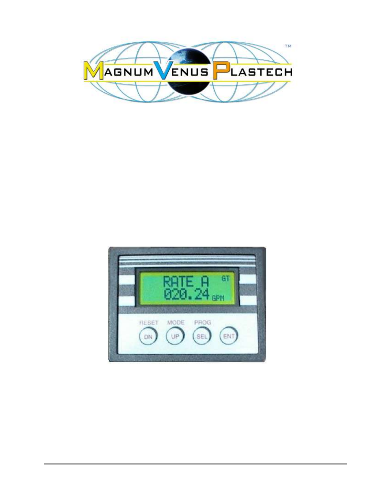
UPMS-1000 Monitoring System
Operations Manual
Model numbers:
UPMS-1000-110vac
UPMS-1000-220vac
MAGNUM VENUS PLASTECH REV 1.02
NOVEMBER 2010 PAGE 1
Page 2

OPERATIONS MANUAL UPMS-1000-XXX
MAGNUM VENUS PLASTECH REV 1.02
NOVEMBER 2010 PAGE 2
Page 3

OPERATIONS MANUAL UPMS-1000-XXX
TABLE OF CONTENTS
CHAPTER 1-Safety and Warning Information ............................................................. 5
Operating Your Polyester System Safely ............................................................................................. 5
1. Introduction .................................................................................................................................. 5
1.2 Personal Safety Equipment ....................................................................................................... 6
2.1 Hazards Associated with Laminating Operations ...................................................................... 6
2.2 Catalyst (Methyl Ethyl Ketone Peroxide) ................................................................................... 7
2.3 Clean-Up Solvents and Resin Diluents ...................................................................................... 8
2.4 Catalyst Diluents ...................................................................................................................... 10
2.5 Cured Laminate, Overspray and Laminate Sandings Accumulation ....................................... 10
2.7 Toxicity of Chemicals ............................................................................................................... 10
2.8 Treatment of Chemical Injuries ................................................................................................ 11
3.0 Equipment Safety ..................................................................................................................... 12
3.1 Emergency Stop Procedures ................................................................................................... 12
3.2 Grounding ................................................................................................................................ 13
CHAPTER 2-Overview ................................................................................................. 15
DESCRPTION ........................................................................................................................................ 15
ITEMS AND TOOLS NEEDED ............................................................................................................... 15
CHAPTER 3-General Setup ........................................................................................ 17
DISPLAY SETUP .................................................................................................................................... 17
DISPLAY PROGRAMMING .................................................................................................................... 18
DISPLAY READOUTS ............................................................................................................................ 21
CHAPTER 4-Calibration .............................................................................................. 22
UPMS-1000 CALIBRATION PROCEDURE ........................................................................................... 22
MANUAL METERING PUMP CALIBRATION .................................................................................... 22
CALIBRATION FOR RATIOS ............................................................................................................ 23
CALIBRATION FOR RATE ................................................................................................................ 24
ENTERING THE KFR FACTOR FOR RATES............................................................................... 24
CHAPTER 7-Troubleshooting .................................................................................... 29
CHAPTER 8-Maintainence/Assembly Drawings ....................................................... 31
JV SERIES FLOW METER .................................................................................................................... 31
SRZ-10 FLOW METER .......................................................................................................................... 33
SRZ-20 FLOW METER .......................................................................................................................... 37
SRZ-40 FLOW METER .......................................................................................................................... 41
SRZ-100 FLOW METER ........................................................................................................................ 45
CHAPTER 9-OEM Documentation.............................................................................. 49
MAGNUM VENUS PLASTECH REV 1.02
NOVEMBER 2010 PAGE 3
Page 4

OPERATIONS MANUAL UPMS-1000-XXX
MAGNUM VENUS PLASTECH REV 1.02
NOVEMBER 2010 PAGE 4
Page 5

OPERATIONS MANUAL UPMS-1000-XXX
CHAPTER 1-Safety and Warning Information
Operating Your Polyester System Safely
1. Introduction
Any tool, if used improperly, can be dangerous. Safety is ultimately the responsibility of those
using the tool. In like manner, safe operation of polyester processes is the responsibility of those
who use such processes and those who operate the equipment. This manual outlines
procedures to be followed in conducting polyester operations safety. This system has been
specifically designed for use of Polyester Resin, Gel-Coat, and Methyl Ethyl Ketone Peroxides
(MEKP) applications. Other formulations or blends considered for use in this equipment is
strictly prohibited without the expressed consent by Magnum Venus Plastech Inc. Magnum
Venus Plastech cannot eliminate every danger nor foresee every circumstance that might cause
an injury during equipment operation. Some risks, such as the high pressure liquid stream that
exits the spray tip, are inherent to the nature of the machine operation and are necessary to the
process in order to manufacture the end-product. For this reason, ALL personnel involved in
polyester operations should read and understand the Safety Manual. It is very important for the
safety of employees involved in the operation that equipment operators, maintenance and
supervisory personnel understand the requirements for safe operation. Each user should
examine his own operation, develop his own safety program and be assured that his equipment
operators follow correct procedures. Magnum Venus Plastech hopes that this manual is helpful
to the user and recommends that the precautions in this manual be included in any such
program. Magnum Venus Plastech recommends this Safety Manual remain on your equipment
at all times for your personnel safety. In addition to the manual, Magnum Venus Plastech
recommends that the user consult the regulations established under the Occupational Safety &
Health Act (OSHA), particularly the following sections:
1910.94 Pertaining to Ventilation.
1910.106 Pertaining to flammable liquids
1910.107 Pertaining to spray finishing operations, particularly Paragraph (m) Organic Peroxides
and Dual Component Coatings.
Other standards and recognized authorities to consult are the National Fire Protection
Association (NFPA) bulletins as follows:
NFPA No.33 Chapter 14, Organic Peroxides and Dual Component Materials
NFPA No.63 Dust Explosion Prevention
NFPA No.70 National Electrical Code
NFPA No.77 Static Electricity
NFPA No.91 Blower and Exhaust System
NFPA No.654 Plastics Industry Dust Hazards
Type of Fire Extinguishing equipment recommended: Fire Extinguisher – code ABC, rating
number 4a60bc.
Extinguishing Media – Foam, Carbon Dioxide, Dry Chemical, Water Fog.
MAGNUM VENUS PLASTECH REV 1.02
NOVEMBER 2010 PAGE 5
Page 6

OPERATIONS MANUAL UPMS-1000-XXX
Copies of the above bulletins are available, at a nominal charge from:
National Fire Protection Association
470 Atlantic Avenue
Boston, MA 02210
Research Report No.11 of the American Insurance Association deal with “Fire, Explosion and
Health Hazards of Organic Peroxides”. It is published by:
American Insurance Association
85 John Street
New York, NY 10038
Local codes and authorities also have standards to be followed in the operation of your spraying
equipment. Your insurance carrier will be helpful in answering questions that arise in your
development of safe procedures.
1.2 Personal Safety Equipment
Magnum Venus Plastech recommends the following Personal Safety Equipment for conducting
safe operations of the Polyester Systems:
Magnum Venus Plastech recommends that the user consult the state and local
regulations established for all Safety equipment listed.
2.0 Material Safety
2.1 Hazards Associated with Laminating Operations
The major hazards which should be guarded against in polyester laminating operations are
those associated with:
1. The flammability and explosion dangers of the catalyst normally used – Methyl Ethyl Ketone
Peroxide (MEKP).
2. The flammability dangers of clean-up solvents sometimes used (Magnum Venus Plastech
recommends that clean-up solvents be non-flammable), and of resin diluents used, such as
styrene.
3. The flammability dangers of catalyst diluents, if used. (Magnum Venus Plastech recommends
that catalyst not be diluted.
4. The flammability dangers of the uncured liquid resins used.
5. The combustibility dangers of the cured laminate, accumulations of over spray, and laminate
sandings.
6. The toxicity dangers of all the chemicals used in laminating operations with respect to
ingestion, inhalation and skin and eye hazards.
MAGNUM VENUS PLASTECH REV 1.02
NOVEMBER 2010 PAGE 6
Page 7

OPERATIONS MANUAL UPMS-1000-XXX
2.2 Catalyst (Methyl Ethyl Ketone Peroxide)
MEKP is among the more hazardous materials found in commercial channels. The safe
handling of the “unstable (reactive)” chemicals presents a definite challenge to the plastics
industry. The highly reactive property which makes MEKP valuable to the plastics industry in
producing the curing reaction of polyester resins also produces the hazards which require great
care and caution in its storage, transportation, handling, processing and disposal. MEKP is a
single chemical. Various polymeric forms may exist which are more or less hazardous with
respect to each other. These differences may arise not only from different molecular structures
(all are, nevertheless, called “MEKP”) and from possible trace impurities left from the
manufacture of the chemicals, but may also arise by contamination of MEKP with other
materials in its storage or use. Even a small amount of contamination with acetone, for instance,
may produce an extremely shock-sensitive and explosive compound.
Contamination with promoters or materials containing promoters, such as laminate
sandings, or with any readily oxidizing material, such as brass or iron, will cause
exothermic “redox” reactions which can become explosive in nature. Heat applied to
MEKP, or heat build-up from contamination reactions can cause it to reach what is called
its Self-Accelerating Decomposition Temperature (SADT).
Researchers have reported measuring pressure rates-of-rise well in excess of 100,000 psi per
second when certain MEKP’s reach their SADT. (For comparison, the highest pressure rate-of-
rise listed in NFPA Bulletin NO.68, “Explosion Venting”, is 12,000 psi per second for an
explosion of 12% acetylene and air. The maximum value listed for a hydrogen explosion is
10,000 psi per second. Some forms of MEKP, if allowed to reach their SADT, will burst even an
open topped container. This suggests that it is not possible to design a relief valve to vent this
order of magnitude of pressure rate-of-rise. The user should be aware that any closed
container, be it a pressure vessel, surge chamber, or pressure accumulator, could explode
under certain conditions. There is no engineering substitute for care by the user in handling
organic peroxide catalysts. If, at any time, the pressure relieve valve on top of the catalyst tank
should vent, the area should be evacuated at once and the fire department called. The venting
could be the first indication of a heat, and therefore, pressure build-up that could eventually lead
to an explosion. Moreover, if a catalyst tank is sufficiently full when the pressure relief valve
vents, some catalyst may spray out, which could cause eye injury. For this reason, and many
others, anyone whose job puts them in an area where this vented spray might go, should
always wear full eye protection even when laminating operations are not taking place.
Safety in handling MEKP depends to a great extent on employee education, proper safety
instructions and safe use of the chemicals and equipment. Workers should be thoroughly
informed of the hazards that may result form improper handling of MEKP, especially in regards
to contamination, heat, friction and impact. They should be thoroughly instructed regarding the
proper action to be taken in the storage, use and disposal of MEKP and other hazardous
materials used in the laminating operation. In addition, users should make every effort to:
A. Store MEKP in a cool, dry place in original containers away from direct sunlight and away
from other chemicals.
B. Keep MEKP away from heat, sparks and open flames.
C. Prevent contamination of MEKP with other materials, including polyester over spray and
sandings, polymerization accelerators and promoters, brass, aluminum and non-stainless
steels.
D. Never add MEKP to anything that is hot, since explosive decomposition may result.
MAGNUM VENUS PLASTECH REV 1.02
NOVEMBER 2010 PAGE 7
Page 8

OPERATIONS MANUAL UPMS-1000-XXX
E. Avoid contact with skin, eyes and clothing. Protective equipment should be worn at all times.
During clean-up of spilled MEKP, personal safety equipment, gloves and eye protection must be
worn. Fire fighting equipment should be at hand and ready.
F. Avoid spillage, which can heat up to the point of self-ignition.
G. Repair any leaks discovered in the catalyst system immediately, and clean up the leaked
catalyst at once in accordance with the catalyst manufacturer’s instructions.
H. Use only original equipment or equivalent parts from Magnum Venus Plastech in the catalyst
system (i.e.: hoses, fitting, etc.) because a dangerous chemical reaction may result between
substituted parts and MEKP.
I. Catalyst accumulated from the purging of hoses or the measurement of fluid output deliveries
should never be returned to the supply tank, such catalyst should be diluted with copious
quantities of clean water and disposed of in accordance with the catalyst manufacturer’s
instructions.
The extent to which the user is successful in accomplishing these ends and any additional
recommendations by the catalyst manufacturer determines largely the safety that will be present
in his operation.
2.3 Clean-Up Solvents and Resin Diluents
WARNING
A hazardous situation may be present in your pressurized fluid system! Hydrocarbon
Solvents can cause an explosion when used with aluminum or galvanized components in
a closed (pressurized) fluid system (pump, heaters, filters, valves, spray guns, tanks,
etc.). The explosion could cause serious injury, death and/or substantial property
damage. Cleaning agents, coatings, paints, etc. may contain Halogenated Hydrocarbon
Solvents. Some Magnum Venus Plastech spray equipment includes aluminum or
galvanized components and will be affected by Halogenated Hydrocarbon Solvents.
A. There are three key elements to the Halogenated Hydrocarbon (HHC) solvent hazard.
a. The presence of HHC solvents. 1,1,1 – Trichloroethane and Methylene Chloride are
the most common of these solvents. However, other HHC solvents are suspect if
used; either as part of paint or adhesives formulation, or for clean-up flushing.
b. Aluminum or Galvanized Parts. Most handling equipment contains these
elements. In contact with these metals, HHC solvents could generate a corrosive
reaction of a catalytic nature.
b. Equipment capable of withstanding pressure. When HHC solvent contact aluminum
or galvanized parts inside a closed container such as a pump, spray gun, or fluid
handling system, the chemical reaction can, over time, result in a build-up of heat
and pressure, which can reach explosive proportions.
When all three elements are present, the result can be an extremely violent explosion. The
reaction can be sustained with very little aluminum or galvanized metal; any amount of
aluminum is too much.
A. The reaction is unpredictable. Prior use of an HHC solvent without incident (corrosion or
explosion) does NOT mean that such use is safe. These solvents can be dangerous alone (as a
clean-up or flushing agent) or when used as a component or a coating material. There is no
known inhibitor that is effective under all circumstances. Furthermore, the mixing of HHC
MAGNUM VENUS PLASTECH REV 1.02
NOVEMBER 2010 PAGE 8
Page 9

OPERATIONS MANUAL UPMS-1000-XXX
solvents with other materials or solvents, such as MEKP, alcohol, and toluene, may render the
inhibitors ineffective.
B. The use of reclaimed solvents is particularly hazardous. Reclaimers may not add any
inhibitors. Also, the possible presence of water in reclaimed solvents could feed the reaction.
C. Anodized or other oxide coatings cannot be relied upon to prevent the explosive reaction.
Such coatings can be worn, cracked, scratched, or too thin to prevent contact. There is no
known way to make oxide coatings or to employ aluminum alloys, which will safely prevent the
chemical reaction under all circumstances.
D. Several solvent suppliers have recently begun promoting HHC solvents for use in coating
systems. The increasing use of HHC solvents is increasing the risk. Because of their exemption
from many State Implementation Plans as Volatile Organic Compounds (VOC’s), their low
flammability hazard, and their not being classified as toxic or carcinogenic substances, HHC
solvents are very desirable in many respects.
WARNING: Do not use Halogenated Hydrocarbon solvents in pressurized fluid systems
having aluminum or galvanized wetted parts.
NOTE: Magnum Venus Plastech is aware of NO stabilizers available to prevent
Halogenated Hydrocarbon solvents from reaction under all conditions with aluminum
components in closed fluid system. TAKE IMMEDIATE ACTION… Halogenated
Hydrocarbon solvents are dangerous when used with aluminum components in a closed
fluid system.
A. Consult your material supplier to determine whether your solvent or coating contains
Halogenated Hydrocarbon Solvents.
B. Magnum Venus Plastech recommends that you contact your solvent supplier regarding the
best non-flammable clean-up solvent with the heat toxicity for your application.
C. If, however, you find it necessary to use flammable solvents, they must be kept in approved,
electrically grounded containers.
D. Bulk solvent should be stored in a well-ventilated, separate building, 50 feet away from your
main plant.
E. You should allow only enough solvent for one day’s use in your laminating area.
F. “NO SMOKING” signs must be posted and observed in all areas of storage or where solvents
and other flammable materials are used.
G. Adequate ventilation (as covered in OSHA Section 1910.94 and NFPA No.91) is important
wherever solvents are stored or used, to minimize, confine and exhaust the solvent vapors.
H. Solvents should be handled in accordance with OSHA Section 1910.106 and 1910.107.
MAGNUM VENUS PLASTECH REV 1.02
NOVEMBER 2010 PAGE 9
Page 10

OPERATIONS MANUAL UPMS-1000-XXX
2.4 Catalyst Diluents
Magnum Venus Plastech spray-up and gel-coat systems currently produced are designed so
that catalyst diluents are not required. Magnum Venus Plastech, therefore, recommends that
diluents not be used. This avoids the possible contamination which could lead to an explosion
due to the handling and mixing of MEKP and diluents. In addition, it eliminates any problems
from the diluents being contaminated through rust particles in drums, poor quality control on the
part of the diluents suppliers, or any other reason. If, however, diluents are absolutely required,
contact your catalyst supplier and follow his instructions explicitly. Preferable, the supplier
should premix the catalyst to prevent possible “on the job” contamination while mixing.
WARNING
If diluents are not used, it should be remembered that catalyst spillage, gun, hose and
packing leaks are potentially more hazardous, since each drop contains a higher
concentration of catalyst, and therefore will react quicker with over spray and the leak.
2.5 Cured Laminate, Overspray and Laminate Sandings Accumulation
A. Remove all accumulations of overspray, FRP sandings, etc. from the building as they occur.
If this waste is allowed to build up, spillage of catalyst is more likely to start a fire, in addition, the
fire would burn hotter and longer.
B. Floor coverings, if used, should be non-combustible.
C. Spilled or leaked catalyst may cause a fire if it comes in contact with an FRP product, over-
sprayed chop or resin, FRP sandings or any other material with MEKP.
To prevent this spillage and leakage, you should:
1. Maintain your Magnum Venus Plastech System. Check the gun several times daily for
catalyst and resin packing or valve leaks. REPAIR ALL LEAKS IMMEDIATELY.
2. Never leave the gun hanging over, or lying inside the mold. A catalyst leak in this situation
would certainly damage the part, possibly the mold, and may cause a fire.
3. Inspect resin and catalyst hoses daily for wear or stress at the entry and exits of the boom
sections and at the hose and fittings. Replace if wear or weakness is evident or suspected.
4. Arrange the hoses and fiberglass roving guides so that the fiberglass strands DO NOT rub
against any of the hoses at any point. If allowed to rub, the hose will be cut through, causing a
hazardous leakage of material which could increase the danger of fire. Also, the material may
spew onto personnel in the area.
2.7 Toxicity of Chemicals
A. Magnum Venus Plastech recommends that you consult OSHA Sections 1910.94, 1910.106,
1910.107 and NFPA No.33, Chapter 14, and NFPA No.91.
B. Contact your chemical supplier(s) and determine the toxicity of the various chemicals used as
well as the best methods to prevent injury, irritation and danger to personnel.
C. Also determine the best methods of first aid treatment for each chemical used in your plant.
MAGNUM VENUS PLASTECH REV 1.02
NOVEMBER 2010 PAGE 10
Page 11

OPERATIONS MANUAL UPMS-1000-XXX
2.8 Treatment of Chemical Injuries
Great care should be used in handling the chemicals (resins, catalyst and solvents) used in
polyester systems. Such chemicals should be treated as if they hurt your skin and eyes and as if
they are poison to your body. For this reason, Magnum Venus Plastech recommends the use of
protective clothing and eye wear in using polyester systems. However, users should be
prepared in the event of such an injury. Precautions include:
1. Know precisely what chemicals you are using and obtain information from your chemical
supplier on what to do in the event the chemical gets onto your skin or into the eyes, or is
swallowed.
2. Keep this information together and easily available so that it may be used by those
administering first aid or treating the injured person.
3. Be sure the information from your chemical supplier includes instructions on how to treat any
toxic effects the chemicals have.
WARNING
Contact your doctor immediately in the event of any injury and give him the information
you have collected. If your information includes first aid instructions, administer first aid
immediately while you are contacting your doctor.
Fast treatment of the outer skin and eyes that contact such chemicals generally includes
immediate and thorough washing of the exposed skin and immediate and continuous flushing of
the eyes with lots of clean water for at least 15 minutes or more. These general instructions of
first aid treatment, however, may be incorrect for some chemicals; that is why you must know
the chemicals and treatment before an accident occurs. Treatment for swallowing a chemical
frequently depends upon the nature of the chemical.
NOTE: Refer to your System User Manual for complete and detailed operating
instructions and service information.
MAGNUM VENUS PLASTECH REV 1.02
NOVEMBER 2010 PAGE 11
Page 12

OPERATIONS MANUAL UPMS-1000-XXX
3.0 Equipment Safety
WARNING
Magnum Venus Plastech suggest that personal safety equipment such as EYE
GOGGLES, GLOVES, EAR PROTECTION, and RESPIRATORS be worn when servicing or
operating this equipment. Ear protection should be worn when operating a fiberglass
chopper to protect against hearing loss since noise levels can be as high as 116 dB
(decibels). This equipment should only be operated or serviced by technically trained
personnel!
WARNING
Never place fingers, hands, or any body part near or directly in front of the spray gun
fluid tip. The force of the liquid as it exits the spray tip can cause serious injury by
shooting liquid through the skin. NEVER LOOK DIRECTLY INTO THE GUN SPRAY TIP OR
POINT THE GUN AT OR NEAR ANOTHER PERSON. (TREAT THE GUN AS IF IT WERE A
LOADED PISTOL.)
3.1 Emergency Stop Procedures
The following steps should be followed in order to stop the machinery in an emergency situation
1. The ball valve located where the air enters the power head of the resin pump, should be
moved to the “OFF” or closed position. To do this, simply rotate the lever on the ball valve
90 degrees. Doing this will cause all the system air to bleed out of the system in a matter of
a few seconds, making the system incapable of operating
NOTE: Step 2 is a precautionary step and should be followed whenever the above
mentioned ball valve is activated to the stop mode. Failure to do so, can damage the
regulators and components on reactivating to the “ON” position.
2. Turn all system regulators to the “OFF” position (counter-clockwise) position
NOTE: Verify that the Catalyst relief line, located on the catalyst manifold, and the resin
return line, located on the resin filter, are secured relieving catalyst and resin fluid
pressure.
3. Catalyst pressure in the catalyst pump can be eliminated by rotating the ball valve on the
catalyst manifold 90 degrees to the “open” or “on” position.
Note: The “open” or “on” position is when the ball valve handle is parallel (in line) with
the ball valve body. The “closed” or “off” position is when the ball valve handle is
perpendicular (across) the ball valve body.
4. Resin pressure in the resin pump can be eliminated by rotating the ball valve on the resin
filter 90 degrees to the “open” or “on” position. Place a container under the ball valve to
catch any resin that is ejected out of the valve.
MAGNUM VENUS PLASTECH REV 1.02
NOVEMBER 2010 PAGE 12
Page 13

OPERATIONS MANUAL UPMS-1000-XXX
3.2 Grounding
Grounding an object means providing an adequate path for the flow of the electrical charge from
the object to the ground. An adequate path is one that permits charge to flow from the object
fast enough that it will not accumulate to the extent that a spark can be formed. It is not possible
to define exactly what will be an adequate path under all conditions since it depends on many
variables. In any event, the grounding means should have the lowest possible electrical
resistance. Grounding straps should be installed on all loose conductive objects in the spraying
area. This includes material containers and equipment. Magnum Venus Plastech recommends
grounding straps be made of AWG No.18 stranded wire as a minimum and the larger wire be
used where possible. NFPA Bulletin No77 states that the electrical resistance of such a
leakage path may be as low as 1 meg ohm (10 ohms) but that resistance as high as 10,000
meg ohms will produce an adequate leakage path in some cases. Whenever flammable or
combustible liquids are transferred from one container to another, or from one container to the
equipment, both containers or container and equipment shall be effectively bonded and
grounded to dissipate static electricity. For further information, see National Fire Protection
Association ( NFPA) 77, titled “Recommended Practice on Static Electrical”. Refer especially to
section 7-7 titled “Spray Application of Flammable and Combustible Materials”. Check with local
codes and authorities for other specific standards that might apply to your application. NEVER
USE HARD MATERIALS SUCH AS WIRE, PINS, ETC., TO CLEAR A PLUGGED GUN. HARD
MATERIALS CAN CAUSE PERMANENT DAMAGE. DAB WITH A BRISTLE BRUSH, BLOW
BACKWARDS WITH AIR UNTIL CLEAR WHILE WEARING A PROTECTIVE EYE SHIELD.
REPEAT AS MANY TIMES AS NECESSARY. DO NOT PERFORM ANY MAINTENANCE OR
REPAIRS UNTIL YOU HAVE FOLLOWED THE PRECAUTIONS STATED ABOVE. IF YOU, AS
AN EQUIPMENT OPERATOR OR SUPERVISOR, DO NOT FEEL THAT YOU HAVE BEEN
ADEQUATELY TRAINED OR INSTRUCTED AND THAT YOU LACK THE TECHNICAL
KNOWLEDGE TO OPERATE OR PERFORM MAINTENANCE ON A PIECE OF MAGNUM
VENUS PLASTECH EQUIPMENT, PLEASE CALL MAGNUM VENUS PLASTECH BEFORE
OPERATING OR PERFORMING MAINTENANCE ON THE EQUIPMENT. IF YOU HAVE ANY
QUESTIONS REGARDING THE ABOVE PRECAUTIONS OR ANY SERVICE OR OPERATION
PRECEDURES, CALL YOUR MAGNUM VENUS PLASTECH DISTRIBUTOR OR MAGNUM
VENUS PLASTECH.
NOTICE: All statements, information and data given herein are believed to be accurate
and reliable but are presented without guaranty, warranty or responsibility of any kind
express or implied. The user should not assume that all safety measures are indicated
or that other measures are not required.
DANGER: Contaminated catalyst may cause Fire or Explosion. Before working on the
catalyst pump or catalyst accumulator, wash hands and tools thoroughly. Be sure work
area is free of dirt, grease or resin. Clean catalyst system components with clean water
only.
DANGER: Eye, skin and respiration hazard. The Catalyst, MEKP, may cause blindness,
skin irritation or breathing difficulty. Keep hands away from face. Keep food and drink
away from work area.
WARNING: Please refer to your catalyst manufacturer’s safety information regarding the
safe handling and storage of catalyst. Wear appropriate safety equipment as
recommended.
MAGNUM VENUS PLASTECH REV 1.02
NOVEMBER 2010 PAGE 13
Page 14

OPERATIONS MANUAL UPMS-1000-XXX
MAGNUM VENUS PLASTECH REV 1.02
NOVEMBER 2010 PAGE 14
Page 15

OPERATIONS MANUAL UPMS-1000-XXX
CHAPTER 2-Overview
DESCRPTION
The UPMS-1000 Monitoring System can be used wherever 2 components are being dispensed. The
UPMS-1000 will monitor both components individually and report back ratios, flow rates, and material
totals.
Using high precision, straight or helical gear flow transmitters, insures that each component is being
monitored precisely. Each meter will feedback to a small PLC which when properly calibrated will report
corresponding ratios, flow rates and totals.
Each flow meter is machined with high precision, utilizes high quality Teflon seals and when sized
properly will not impede flow rates.
ITEMS AND TOOLS NEEDED
.
Scale capable of display weight increments to .01 lbs and will weigh up to 5 lbs.
Plastic or paper quart cups.
Calculator.
Set of Allen keys.
6” Adjustable wrench.
Ratio block assembly for MVP Pro Series mixing head.
MAGNUM VENUS PLASTECH REV 1.02
NOVEMBER 2010 PAGE 15
Page 16

OPERATIONS MANUAL UPMS-1000-XXX
MAGNUM VENUS PLASTECH REV 1.02
NOVEMBER 2010 PAGE 16
Page 17

OPERATIONS MANUAL UPMS-1000-XXX
CHAPTER 3-General Setup
DISPLAY SETUP
1. Cycle display using the MODE button, until the main logo is displayed.
2. Press and hold the ENT button until the display enters program mode. At this point you should
see DISPLAY 00 with LOGO underneath. What this means is that the 00 display will show the
LOGO screen. DISPLAY 00 should always be programmed to the LOGO setting.
3. Once in program mode pressing the DN button will turn the display OFF/ON. Pressing the SEL
button will cycle through the available displays.
4. Once you have chosen a readout for the display location Press ENT button again. This will set
the current selection to memory and increment to the next display for programming.
5. Repeat step 3 until all the displays are programmed to the initial matrix below.
The following displays are always on.
DISPLAY 00 LOGO
DISPLAY 01 RATIO A B
DISPLAY 02 TOTAL A B
DISPLAY 03 STATUS ONE
DISPLAY 04 WARNINGS
The next set of displays must be on for calibration of the UPMS-1000 to the metering pump. They can
be left on or turned off after calibration. Customer preference.
DISPLAY 05 RATE A
DISPLAY 06 RATE B
DISPLAY 07 TOTAL A
DISPLAY 08 TOTAL B
DISPLAY 09-19 OFF
There are multiple displays available for viewing. The FEM-03 will display 19 readings at a time.
Consult the FEM-03 manual and the customer to decide which additional displays need to be
programmed.
MAGNUM VENUS PLASTECH REV 1.02
NOVEMBER 2010 PAGE 17
Page 18

OPERATIONS MANUAL UPMS-1000-XXX
DISPLAY PROGRAMMING
RATIO A B
Cycle display using the MODE button, until the RATIO A B is displayed.
Press and hold the ENT button until the display enters program mode. At this point you should
see IDEAL A B, with a number underneath it. The first digit should be blinking.
Press SEL until the decimal point is blinking. Using the UP or DN button, move the decimal until
3 decimal places are set. Then, using the SEL and UP and DN buttons, set the IDEAL A B to
the appropriate value.
Press ENT to accept IDEAL A B setting. This will then move to the next screen.
Set the WARNING A B decimal by pressing SEL until the decimal point is blinking. Using the
UP or DN button, move the decimal until 2 decimal places are set. Then, using the SEL and UP
and DN buttons, set the WARNING A B to the appropriate value.
Press ENT to accept WARNING A B setting. This will then move to the next screen.
Set the ALARM A B decimal by pressing SEL until the decimal point is blinking. Using the
UP or DN button, move the decimal until 2 decimal places are set. Then, using the SEL and UP
and DN buttons, set the ALARM A B to the appropriate value.
Press ENT to accept ALARM A B setting. This will then move to the next screen.
Set the TARGET NBR using the SEL and UP and DN buttons, set the TARGET NBR to
the appropriate value. A good value is 500 to start with. To calculate the update speed in
seconds, look at the STATUS ONE DISPLAY while unit is running and determine the
highest pulse rate. The STATUS ONE DISPLAY reads pulses per second (Hz). Divide the
TARGET NBR by the maximum pulse rate of either channel A or B and this will give you
update time in seconds.
Note: This variable is used to set the number of pulses sampled before a ratio calculation is
made and is programmed in pulses. TARGET NUMBER is used for the RATIO A/B and RATIO
B/A calculation. A ratio calculation is performed whenever either channel has accumulated the
TARGET NUMBER of pulses since the last ratio calculation. If the TARGET NBR is too small, the
ratio calculation can consistently produce large errors. If the TARGET NBR is too large, the ratio
will not be calculated frequently. The allowable range for TARGET NBR is from 1 to 65534. The
recommended typical range for values is from 200 to 2000. The initial value for TARGET NBR is
500.
MAGNUM VENUS PLASTECH REV 1.02
NOVEMBER 2010 PAGE 18
Page 19
OPERATIONS MANUAL UPMS-1000-XXX
DISPLAY PROGRAMMING (cont)
TOTAL A B
No programming necessary.
STATUS ONE
No programming necessary.
WARNINGS
Although you can program alarms from here it is recommended that the alarms be programmed
from the RATIO A B setup.
RATE A
Cycle display using the MODE button, until the RATE A is displayed.
Press SEL until the decimal point is blinking. Using the UP or DN button, move the decimal until
3 decimal places are set. Then, using the SEL and UP and DN buttons, set the KFR A
VALUE to the appropriate value. At this point .500 should be used. The KFR A VALUE will
be set in the Calibration section.
Press ENT to accept KFR A VALUE setting. This will then move to the next screen.
Press ENT to accept SAMPLE A setting (Leave at 10). This will then move to the next screen.
Set the ENG UNITS A display by using the UP or DN and SEL buttons. Either set to KG/M,
GR/M, LBS/M or OZ/M
Note: Remember what measurement was setup to display. This is the measurement that needs to be used
during the calibration process.
Press ENT to accept ENG UNITS A setting. This will return you to the RATE A display
RATE B
Cycle display using the MODE button, until the RATE B is displayed.
Press SEL until the decimal point is blinking. Using the UP or DN button, move the decimal until
3 decimal places are set. Then, using the SEL and UP and DN buttons, set the KFR B
VALUE to the appropriate value. At this point .500 should be used. The KFR B VALUE will
be set in the Calibration section.
Press ENT to accept KFR B VALUE setting. This will then move to the next screen.
Press ENT to accept SAMPLE B setting (Leave at 10). This will then move to the next screen.
Set the ENG UNITS B display by using the UP or DN and SEL buttons. Either set to KG/M,
GR/M, LBS/M or OZ/M
Note: Remember what measurement was setup to display. This is the measurement that needs to be used
during the calibration process.
Press ENT to accept ENG UNITS B setting. This will return you to the RATE B display
MAGNUM VENUS PLASTECH REV 1.02
NOVEMBER 2010 PAGE 19
Page 20

OPERATIONS MANUAL UPMS-1000-XXX
TOTAL A
Cycle display using the MODE button, until the TOTAL A is displayed.
Press and hold the ENT button until the display enters program mode. At this point you should see KFT
A VALUE, with a number underneath it. The first digit should be blinking.
Press SEL until the decimal point is blinking. Using the UP or DN button, move the decimal until 3
decimal places are set. Then, using the SEL and UP and DN buttons, set the KFT A VALUE to the
appropriate value. At this point .500 should be used. The KFT A VALUE will be set in the Calibration
section.
Press ENT to accept KFT A VALUE setting. This will then move to the next screen.
Set the ENG UNITS A display by using the UP or DN and SEL buttons. Either set to KG, GR, LBS or
OZ.
Note: Remember what measurement was setup to display. This is the measurement that needs to be used
during the calibration process.
Press ENT to accept ENG UNITS A setting. This will return you to the TOTAL A display.
TOTAL B
Cycle display using the MODE button, until the TOTAL B is displayed.
Press and hold the ENT button until the display enters program mode. At this point you should see KFT
B VALUE, with a number underneath it. The first digit should be blinking.
Press SEL until the decimal point is blinking. Using the UP or DN button, move the decimal until 3
decimal places are set. Then, using the SEL and UP and DN buttons, set the KFT B VALUE to the
appropriate value. At this point .500 should be used. The KFT A VALUE will be set in the Calibration
section.
Press ENT to accept KFT B VALUE setting. This will then move to the next screen.
Set the ENG UNITS B display by using the UP or DN and SEL buttons. Either set to KG, GR, LBS or
OZ.
Note: Remember what measurement was setup to display. This is the measurement that needs to be used
during the calibration process.
Press ENT to accept ENG UNITS B setting. This will return you to the TOTAL A display.
MAGNUM VENUS PLASTECH REV 1.02
NOVEMBER 2010 PAGE 20
Page 21

OPERATIONS MANUAL UPMS-1000-XXX
DISPLAY READOUTS
RATIO A B
Monitors the ratio of component A to component B
TOTAL A B
Displays the individual totals of components A and B dispensed
STATUS ONE
Maintenance display to check for flow meter pickup operation and erratic counts
WARNINGS
Shows the values at which the alarms are set for the RATIO A B
RATE A
Displays A component flow rate
RATE B
Displays B component flow rate
TOTAL A
Displays the total of component A dispensed
TOTAL B
Displays the total of component B dispensed
MAGNUM VENUS PLASTECH REV 1.02
NOVEMBER 2010 PAGE 21
Page 22

OPERATIONS MANUAL UPMS-1000-XXX
CHAPTER 4-Calibration
UPMS-1000 CALIBRATION PROCEDURE
Once all the displays are programmed, the UPMS-1000 needs to be calibrated to the metering pumps
that it is attached to.
To calibrate the UPMS-1000 to the metering pump 3 tests need to be performed.
The tests are:
Gallons/Liters per minute from each metering pump.
KG/GM/LBS/OZ sample from each metering pump
Manual ratio test of the metering pumps together.
The metering pumps must be calibrated manually and double checked before attempting to calibrate the
UPMS-1000
MANUAL METERING PUMP CALIBRATION
1. Using the chart supplied, set the variable fluid section to the correct placement on the scale.
2. Set the main pump pressure to 0 psi and turn on the recirculation circuit of the machine.
3. Slowly bring up the main pump pressure until pressure has developed and is stabilized on the
output pressure gauges.
4. Let the pump cycle several times to bleed any air out of the system and balance out output
pressures.
5. With the ratio block assembly on the front of the dispensing gun, turn on the gun, wait for
pressures to balance and then run both materials into measuring cups for a weight. Both streams
must be started at the same time into the measuring cups and more weight per cup guarantees a
higher accuracy.
6. Once the ratio has been calculated adjust the variable fluid section accordingly (small increments)
and re run step #5 until correct result is achieved. Running the test 2-3 times after the correct
ratio has been achieved will produce the best results.
Once the Manual Metering Pump Calibration has been performed and verified the UPMS-1000 now
needs to be calibrated to the metering pump.
MAGNUM VENUS PLASTECH REV 1.02
NOVEMBER 2010 PAGE 22
Page 23

OPERATIONS MANUAL UPMS-1000-XXX
CALIBRATION FOR RATIOS
1. With the ratio block assembly on the front of the dispensing gun, turn on the gun, wait for pressures to
balance and come up to operating pressures.
2. Stop the pump system.
3. Cycle the UPMS-1000 display using the MODE button until TOTAL A is displayed.
4. Press the RESET button to zero the display.
5. Press the MODE button to display TOTAL B
6. Press the RESET button to zero the display.
7. Start the pump system
8. Dispense both A and B materials into pre weighed cups.
9. Stop the pump system.
10. Find the net weight of both materials.
11. Cycle the UPMS-1000 display using the MODE button until TOTAL A is displayed.
12. Press and hold the ENT button until the display enters program mode. At this point you will see KFT
A VALUE, with a number underneath it. The first digit should be blinking.
13. Using the UP or DN and SEL buttons adjust the KFT A VALUE.
14. Press the ENT button twice to return to TOTAL A display. Verify the displayed value of the
TOTAL A matches what was weighed in the cup. If the display does not match, return to step 9 and
repeat the process until the displayed value matches the actual value.
15. Once the TOTAL A display has been calibrated, press the ENT button to cycle the display to
TOTAL B
16. Press and hold the ENT button until the display enters program mode. At this point you will see KFT
B VALUE, with a number underneath it. The first digit should be blinking.
17. Using the UP or DN and SEL buttons adjust the KFT B VALUE.
18. Press the ENT button twice to return to TOTAL B display. Verify the displayed value of the
TOTAL B matches what was weighed in the cup. If the display does not match, return to step 13
and repeat the process until the displayed value matches the actual value.
MAGNUM VENUS PLASTECH REV 1.02
NOVEMBER 2010 PAGE 23
Page 24

OPERATIONS MANUAL UPMS-1000-XXX
CALIBRATION FOR RATE
With each flow transmitter there will be a calibration sheet that will supply the average pulses per volume
of specific units. Using the formulas below calculate the KFR value to enter into the display.
KFR VALUE CALCULATIONS FOR RATE
Gallons per Minute:
6000 / Average K-Factor in Pulses per Gallon
Liters per Minute:
6000 / (Average K-Factor in Pulses per cc X 1000)
Pounds per Minute:
6000 / (Average K-Factor in Pulses per Gallon / (Specific Gravity X 8.35)
Kilograms per Minute:
6000 / (Average K-Factor in Pulses per cc X 1000) / Specific Gravity
ENTERING THE KFR FACTOR FOR RATES
1. Cycle display using the MODE button, until the RATE A is displayed.
2. Press and hold the ENT button until the display enters program mode. At this point you should
see KFR A VALUE, with a number underneath it. The first digit should be blinking.
3. Using the UP or DN and SEL buttons adjust the KFR A VALUE to figures calculated from
above.
4. Press ENT to accept KFR A VALUE setting. This will then move to the next screen.
5. Press ENT to accept SAMPLE A setting.
6. Note: Do not adjust the SAMPLE A SETTING!
7. Press ENT to accept ENG UNITS A setting.
8. Note: Do not adjust the SAMPLE A SETTING!
9. Calibration for RATE A is now complete.
MAGNUM VENUS PLASTECH REV 1.02
NOVEMBER 2010 PAGE 24
Page 25

OPERATIONS MANUAL UPMS-1000-XXX
10. Cycle display using the MODE button, until the RATE B is displayed.
11. Press and hold the ENT button until the display enters program mode. At this point you should
see KFR B VALUE, with a number underneath it. The first digit should be blinking.
12. Using the UP or DN and SEL buttons adjust the KFR B VALUE to figures calculated from
above.
13. Press ENT to accept KFR B VALUE setting. This will then move to the next screen.
14. Press ENT to accept SAMPLE B setting.
15. Note: Do not adjust the SAMPLE A SETTING!
16. Press ENT to accept ENG UNITS B setting.
17. Note: Do not adjust the SAMPLE A SETTING!
18. Calibration for RATE B is now complete.
After this is complete, a test sample should be dispensed into a cup and timed while noting the reading on
the display. If the desired result is not achieved it is possible to adjust the KFR factor in small increments
to match the output of the dispensing unit.
MAGNUM VENUS PLASTECH REV 1.02
NOVEMBER 2010 PAGE 25
Page 26

OPERATIONS MANUAL UPMS-1000-XXX
MAGNUM VENUS PLASTECH REV 1.02
NOVEMBER 2010 PAGE 26
Page 27

UPMS-1000 Monitoring System
Calibration/Setup
Model numbers:
UPMS-1000-110vac
UPMS-1000-220vac
RATIO A B
IDEAL A B
WARNING A B
ALARM A B
TARGET NBR
RATE A
KFR A VALUE
SAMPLE A
ENG UNITS A
RATE B
KFR B VALUE
SAMPLE B
ENG UNITS B
TOTAL A
KFR A VALUE
ENG UNITS A
TOTAL B
KFR B VALUE
ENG UNITS B
OPERATIONS MANUAL UPMS-1000-XXX
MAGNUM VENUS PLASTECH REV 1.02
NOVEMBER 2010 PAGE 27
Page 28

OPERATIONS MANUAL UPMS-1000-XXX
MAGNUM VENUS PLASTECH REV 1.02
NOVEMBER 2010 PAGE 28
Page 29

Unit will not power on
Check incoming power
Check internal fuses/circuit breakers
Check internal fuse on back of display
Displays will not read
Check connections to flow meter pickups
Check KFT and KFR values
Readout has large errors
Check charges on accumulators
Set TARGET NBR to higher value
OPERATIONS MANUAL UPMS-1000-XXX
CHAPTER 7-Troubleshooting
Problem Cause
MAGNUM VENUS PLASTECH REV 1.02
NOVEMBER 2010 PAGE 29
Page 30

OPERATIONS MANUAL UPMS-1000-XXX
MAGNUM VENUS PLASTECH REV 1.02
NOVEMBER 2010 PAGE 30
Page 31

OPERATIONS MANUAL UPMS-1000-XXX
CHAPTER 8-Maintainence/Assembly Drawings
JV SERIES FLOW METER
MAGNUM VENUS PLASTECH REV 1.02
NOVEMBER 2010 PAGE 31
Page 32

OPERATIONS MANUAL UPMS-1000-XXX
MAGNUM VENUS PLASTECH REV 1.02
NOVEMBER 2010 PAGE 32
Page 33

OPERATIONS MANUAL UPMS-1000-XXX
SRZ-10 FLOW METER
MAGNUM VENUS PLASTECH REV 1.02
NOVEMBER 2010 PAGE 33
Page 34

OPERATIONS MANUAL UPMS-1000-XXX
MAGNUM VENUS PLASTECH REV 1.02
NOVEMBER 2010 PAGE 34
Page 35

OPERATIONS MANUAL UPMS-1000-XXX
MAGNUM VENUS PLASTECH REV 1.02
NOVEMBER 2010 PAGE 35
Page 36

OPERATIONS MANUAL UPMS-1000-XXX
MAGNUM VENUS PLASTECH REV 1.02
NOVEMBER 2010 PAGE 36
Page 37

OPERATIONS MANUAL UPMS-1000-XXX
SRZ-20 FLOW METER
MAGNUM VENUS PLASTECH REV 1.02
NOVEMBER 2010 PAGE 37
Page 38

OPERATIONS MANUAL UPMS-1000-XXX
MAGNUM VENUS PLASTECH REV 1.02
NOVEMBER 2010 PAGE 38
Page 39

OPERATIONS MANUAL UPMS-1000-XXX
MAGNUM VENUS PLASTECH REV 1.02
NOVEMBER 2010 PAGE 39
Page 40

OPERATIONS MANUAL UPMS-1000-XXX
MAGNUM VENUS PLASTECH REV 1.02
NOVEMBER 2010 PAGE 40
Page 41

OPERATIONS MANUAL UPMS-1000-XXX
SRZ-40 FLOW METER
MAGNUM VENUS PLASTECH REV 1.02
NOVEMBER 2010 PAGE 41
Page 42

OPERATIONS MANUAL UPMS-1000-XXX
MAGNUM VENUS PLASTECH REV 1.02
NOVEMBER 2010 PAGE 42
Page 43

OPERATIONS MANUAL UPMS-1000-XXX
MAGNUM VENUS PLASTECH REV 1.02
NOVEMBER 2010 PAGE 43
Page 44

OPERATIONS MANUAL UPMS-1000-XXX
MAGNUM VENUS PLASTECH REV 1.02
NOVEMBER 2010 PAGE 44
Page 45

OPERATIONS MANUAL UPMS-1000-XXX
SRZ-100 FLOW METER
MAGNUM VENUS PLASTECH REV 1.02
NOVEMBER 2010 PAGE 45
Page 46

OPERATIONS MANUAL UPMS-1000-XXX
MAGNUM VENUS PLASTECH REV 1.02
NOVEMBER 2010 PAGE 46
Page 47

OPERATIONS MANUAL UPMS-1000-XXX
MAGNUM VENUS PLASTECH REV 1.02
NOVEMBER 2010 PAGE 47
Page 48

OPERATIONS MANUAL UPMS-1000-XXX
MAGNUM VENUS PLASTECH REV 1.02
NOVEMBER 2010 PAGE 48
Page 49

OPERATIONS MANUAL UPMS-1000-XXX
CHAPTER 9-OEM Documentation
MAGNUM VENUS PLASTECH REV 1.02
NOVEMBER 2010 PAGE 49
Page 50

OPERATIONS MANUAL UPMS-1000-XXX
MAGNUM VENUS PLASTECH REV 1.02
NOVEMBER 2010 PAGE 50
Page 51

OPERATIONS MANUAL UPMS-1000-XXX
MAGNUM VENUS PLASTECH REV 1.02
NOVEMBER 2010 PAGE 51
Page 52

OPERATIONS MANUAL UPMS-1000-XXX
MAGNUM VENUS PLASTECH REV 1.02
NOVEMBER 2010 PAGE 52
Page 53

OPERATIONS MANUAL UPMS-1000-XXX
MAGNUM VENUS PLASTECH REV 1.02
NOVEMBER 2010 PAGE 53
Page 54

OPERATIONS MANUAL UPMS-1000-XXX
MAGNUM VENUS PLASTECH REV 1.02
NOVEMBER 2010 PAGE 54
Page 55

OPERATIONS MANUAL UPMS-1000-XXX
MAGNUM VENUS PLASTECH REV 1.02
NOVEMBER 2010 PAGE 55
Page 56

OPERATIONS MANUAL UPMS-1000-XXX
MAGNUM VENUS PLASTECH REV 1.02
NOVEMBER 2010 PAGE 56
Page 57

OPERATIONS MANUAL UPMS-1000-XXX
MAGNUM VENUS PLASTECH REV 1.02
NOVEMBER 2010 PAGE 57
Page 58

OPERATIONS MANUAL UPMS-1000-XXX
MAGNUM VENUS PLASTECH REV 1.02
NOVEMBER 2010 PAGE 58
Page 59

OPERATIONS MANUAL UPMS-1000-XXX
MAGNUM VENUS PLASTECH REV 1.02
NOVEMBER 2010 PAGE 59
Page 60

OPERATIONS MANUAL UPMS-1000-XXX
MAGNUM VENUS PLASTECH REV 1.02
NOVEMBER 2010 PAGE 60
Page 61

OPERATIONS MANUAL UPMS-1000-XXX
MAGNUM VENUS PLASTECH REV 1.02
NOVEMBER 2010 PAGE 61
Page 62

OPERATIONS MANUAL UPMS-1000-XXX
MAGNUM VENUS PLASTECH REV 1.02
NOVEMBER 2010 PAGE 62
Page 63

OPERATIONS MANUAL UPMS-1000-XXX
MAGNUM VENUS PLASTECH REV 1.02
NOVEMBER 2010 PAGE 63
Page 64

OPERATIONS MANUAL UPMS-1000-XXX
MAGNUM VENUS PLASTECH REV 1.02
NOVEMBER 2010 PAGE 64
Page 65

OPERATIONS MANUAL UPMS-1000-XXX
MAGNUM VENUS PLASTECH REV 1.02
NOVEMBER 2010 PAGE 65
Page 66

OPERATIONS MANUAL UPMS-1000-XXX
MAGNUM VENUS PLASTECH REV 1.02
NOVEMBER 2010 PAGE 66
Page 67

OPERATIONS MANUAL UPMS-1000-XXX
MAGNUM VENUS PLASTECH REV 1.02
NOVEMBER 2010 PAGE 67
Page 68

OPERATIONS MANUAL UPMS-1000-XXX
MAGNUM VENUS PLASTECH REV 1.02
NOVEMBER 2010 PAGE 68
Page 69

OPERATIONS MANUAL UPMS-1000-XXX
MAGNUM VENUS PLASTECH REV 1.02
NOVEMBER 2010 PAGE 69
Page 70

OPERATIONS MANUAL UPMS-1000-XXX
MAGNUM VENUS PLASTECH REV 1.02
NOVEMBER 2010 PAGE 70
Page 71

OPERATIONS MANUAL UPMS-1000-XXX
MAGNUM VENUS PLASTECH REV 1.02
NOVEMBER 2010 PAGE 71
Page 72

OPERATIONS MANUAL UPMS-1000-XXX
MAGNUM VENUS PLASTECH REV 1.02
NOVEMBER 2010 PAGE 72
Page 73

OPERATIONS MANUAL UPMS-1000-XXX
MAGNUM VENUS PLASTECH REV 1.02
NOVEMBER 2010 PAGE 73
Page 74

OPERATIONS MANUAL UPMS-1000-XXX
MAGNUM VENUS PLASTECH REV 1.02
NOVEMBER 2010 PAGE 74
Page 75

OPERATIONS MANUAL UPMS-1000-XXX
MAGNUM VENUS PLASTECH REV 1.02
NOVEMBER 2010 PAGE 75
Page 76

OPERATIONS MANUAL UPMS-1000-XXX
MAGNUM VENUS PLASTECH REV 1.02
NOVEMBER 2010 PAGE 76
Page 77

OPERATIONS MANUAL UPMS-1000-XXX
MAGNUM VENUS PLASTECH REV 1.02
NOVEMBER 2010 PAGE 77
Page 78

OPERATIONS MANUAL UPMS-1000-XXX
MAGNUM VENUS PLASTECH REV 1.02
NOVEMBER 2010 PAGE 78
Page 79

OPERATIONS MANUAL UPMS-1000-XXX
MAGNUM VENUS PLASTECH REV 1.02
NOVEMBER 2010 PAGE 79
Page 80

OPERATIONS MANUAL UPMS-1000-XXX
MAGNUM VENUS PLASTECH REV 1.02
NOVEMBER 2010 PAGE 80
Page 81

OPERATIONS MANUAL UPMS-1000-XXX
MAGNUM VENUS PLASTECH REV 1.02
NOVEMBER 2010 PAGE 81
Page 82

OPERATIONS MANUAL UPMS-1000-XXX
Corporate HQ/Mfg. Manufacturing/Sales
5148 113th Ave. 1862 Ives Ave.
Clearwater, FL 33760 USA Kent, WA 98032 USA
Ph: (727) 573-2955 Ph: (253) 854-2660
Fax: (727) 571-3636 Fax: (253) 854-1666
E-mail: info@mvpind.com Web: www.mvpind.com
MAGNUM VENUS PLASTECH REV 1.02
NOVEMBER 2010 PAGE 82
 Loading...