

Page 1
UPLS SYSTEM OVERVIEW UP-XX-XX-XX
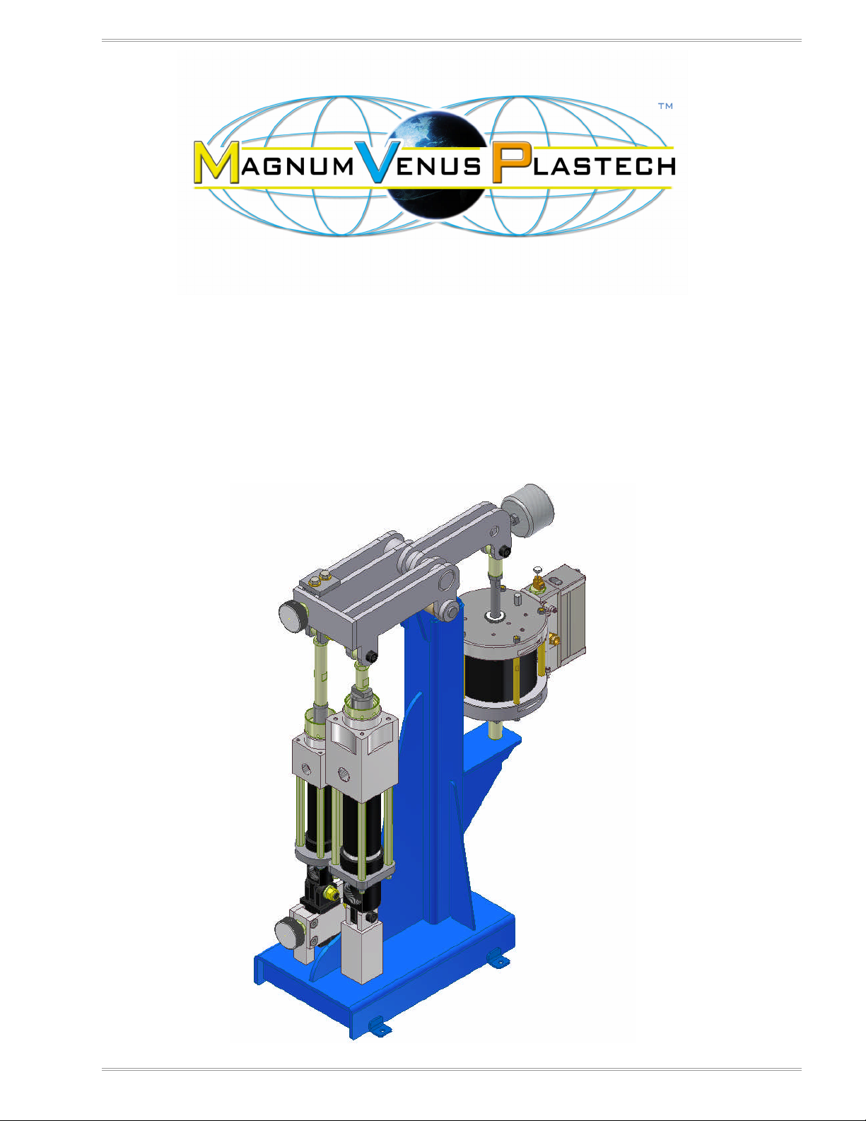
UNIVERSAL PROPORTIONER
System Overview
Model numbers:
UPPA-5-24-24, UPPA-5-46-46, UPPA-7-46-23
UPPA-7-46-23, UPPA-7-46-46, UPPA-7-10-23, UPPA-7-10-46, UPPA-7-10-10
UPPA-10-10-46, UPPA-10-10-10
MAGNUM VENUS PLASTECH REV 1.00
APRIL 2010 PAGE 1
Page 2

UPLS SYSTEM OVERVIEW UP-XX-XX-XX
MAGNUM VENUS PLASTECH REV 1.00
APRIL 2010 PAGE 2
Page 3

UPLS SYSTEM OVERVIEW UP-XX-XX-XX
TABLE OF CONTENTS
CHAPTER 1-Introduction and General Information .................................................... 5
CHAPTER 2-Unit Information ....................................................................................... 7
FLUID SECTIONS CUBIC INCHES PER CYCLE AT 4”STROKE:........................................................ 7
FLUID SECTION RATIO RANGE BY VOLUME: .................................................................................. 7
MAXIMUM FLUID PRESSURE (2,500 TO 2,700 PSI) .......................................................................... 8
PRESSURE CONTROL VALVE .......................................................................................................... 8
AIR MOTORS (POWER HEADS) ........................................................................................................ 8
MIX/DISPENSE GUNS AND RECIRCULATION OPTIONS.................................................................. 9
MATERIALS A & B HOSE SETS FROM PUMP TO GUN..................................................................... 9
FLUSH SYSTEMS............................................................................................................................. 10
CHAPTER 3-Materials Information ............................................................................. 11
MATERIAL FEED .............................................................................................................................. 11
MATERIAL HANDLING ..................................................................................................................... 11
CHAPTER 4-Electrical Information ............................................................................ 13
CHAPTER 5-System Installation ................................................................................ 15
SYSTEM START-UP: ........................................................................................................................ 15
DAILY START-UP PROCEDURE ...................................................................................................... 19
DAILY SHUT-DOWN PROCEDURES ............................................................................................... 21
MAGNUM VENUS PLASTECH REV 1.00
APRIL 2010 PAGE 3
Page 4

UPLS SYSTEM OVERVIEW UP-XX-XX-XX
MAGNUM VENUS PLASTECH REV 1.00
APRIL 2010 PAGE 4
Page 5

UPLS SYSTEM OVERVIEW UP-XX-XX-XX
MVP Universal Proportioner
CHAPTER 1-Introduction and General Information
The Universal Proportioner as the description implies is available in a number of
configurations depending on materials used and customer requirements. In the event
the customer’s process and materials change, the system can be converted to handle
almost all thermoset resins and application with hardware and fluid section conversions.
Generally, this system is for two part Epoxy and Urethane resin systems for pour,
closed molding and spray applications.
(Note: To avoid confusion, manuals will only include assembly drawings and
rebuild instructions for the components included in unit purchase.)
Third component options are also available for low percentage down stream mixing of
additives which will require an additional bolt-on linkage drive package.
MAGNUM VENUS PLASTECH REV 1.00
APRIL 2010 PAGE 5
Page 6

UPLS SYSTEM OVERVIEW UP-XX-XX-XX
MAGNUM VENUS PLASTECH REV 1.00
APRIL 2010 PAGE 6
Page 7

UPLS SYSTEM OVERVIEW UP-XX-XX-XX
CHAPTER 2-Unit Information
Depending on the ratio’s and material outputs required, there are 3-fluid sections
available for the system. Each of the 3-fluid sections are also available made of
stainless steel construction with soft ball seats when vary low viscosity, corrosive
materials are used. One of the three stainless steel fluid sections are used which are
typically standard on the hardener side (adjustable linkage) when epoxy resins are
used.
The stainless steel fluid section soft seats use a Kalrez o-ring. Kalrez is a
perfluoroelastomer with exceptional chemical resistance to many acids and amines.
Only replace as needed, they are not include in the repair kits because of there cost.
Normal pump rebuilds do not require replacement of these o-rings. See fluid section
repair.
FLUID SECTIONS CUBIC INCHES PER CYCLE AT 4”STROKE:
UPLS-1000/1000-SS 24.72 C.I./Cycle
UPLS-4600/4600-SS 9.67 C.I./Cycle
UPLS-2400/2300-SS 4.82 C.I./Cycle
FLUID SECTION RATIO RANGE BY VOLUME:
If the same size fluid sections are used on both A & B materials the ratio range is from
1:1 to 3.10:1
The fluid section mounted onto the adjustable linkage has a range of 4” to 1.290” long
stroke of the piston rod.
With HV and 4600 fluid sections: 2.55:1 to 7.92:1 (10” air motor 17:1 power ratio)
With HV and 2300 fluid sections: 5.12:1 to 15.87:1 (7” air motor 10:1 power ratio)
With 4600 and 2300 fluid sections: 2.00:1 to 6:1 (7” air motor 19:1 power ratio)
With two 2400 fluid sections: 1:1 to 3.10:1 (5” air motor 15:1 power ratio)
(Note: The 2400 fluid sections are not balanced with the other fluid sections listed
above. No additional fluid section options are available with the 2400 section)
MAGNUM VENUS PLASTECH REV 1.00
APRIL 2010 PAGE 7
Page 8

UPLS SYSTEM OVERVIEW UP-XX-XX-XX
MAXIMUM FLUID PRESSURE (2,500 TO 2,700 PSI)
Depending on the size of the air motor, the air operating pressures and the size of the
fluid sections used dictates how high the fluid pressure can reach. Normally, these
pressures will never be met in normal operating ranges. However, if a material hose
had become plugged with set-up resin with the air motor at a high setting (100 psi or
higher) the plugged line could reach these pressures.
A pressure control valve (PLV-1000) is used to prevent pressures from exceeding the
maximum pressure point. Depending on the unit configuration, there may only be one
of these valves on the adjustable linkage pump and in some cases, on both pumps.
The pressure control valves are located on the hard plumbed fittings that exit the
material pump fluid sections. They have green 1/8” poly tubing attached at the top of
the valves which run back to a 3-way pneumatic (Mac valve) valve located off the side
of the air motor.
PRESSURE CONTROL VALVE
The pressure control valve has a spring loaded plunger, the plunger end is in the
material stream. If the material stream reaches pressures of 2,500 to 2,700 psi the
plunger is forced up. Once the plunger opens, it breaks an air circuit which in turn
closes the 3-way valve (Mac valve) that supplies air to the air-motor. When this
happens, air will bleed from the small holes on the side of the pressure control as long
as the gun is in the on position. Please see the PLV-1000 manual for more information.
(NOTE: The pressure control valve does not release fluid pressure. It only shuts
off the air supply to the air motor).
AIR MOTORS (POWER HEADS)
Available Diameters and SCFM air consumption at 40 cycles/min.
60 psi 80 psi
10” Diameter: 72 SCFM 90 SCFM
7” Diameter: 37 SCFM 46 SCFM
5” Diameter: 20 SCFM 25 SCFM
Incoming supply air pressure, regardless of the Air Motor size and operating pressure
can not be any lower then 90 psi. , when running the system. This is critical for the Air
motor pilot valves which affect the air motor change of direction. Use no smaller then
½” diameter hose supply line to unit of clean dry air with no quick disconnects. A ¾”
diameter air hose or larger is recommended when using the 10” air motor at higher
rates.
Customer is responsible for air supply connections with properly sized air hose and
compressed air volume (SCFM) available to system.
MAGNUM VENUS PLASTECH REV 1.00
APRIL 2010 PAGE 8
Page 9

UPLS SYSTEM OVERVIEW UP-XX-XX-XX
MIX/DISPENSE GUNS AND RECIRCULATION OPTIONS
Most systems come standard with two guns but this may not always be the case.
Primary gun is used for mixing and dispensing of the metered materials. The second
gun block uses the same parts as the dispense gun. The second gun block is referred
too as a recirculation gun with the only difference being a bolt-on outlet block that keeps
the two materials separated with hose fittings attached.
Some advantages with the recirculation gun blocks are:
1. Running a ratio check between A & B materials.
2. Releasing the fluid pressure and positioning the fluid piston rods in full down
stroke during shut-down without wasting material.
3. To purge any air out of the feed hoses when changing over to full drum or totes.
4. Temperature control when in-line heaters are added.
High Volume 1:1 Pro gun: This is standard in most cases. Available in automatic and
manual configurations for spray, pour and recirculation operations. No hand held trigger
configuration available because of the weight of the gun.
Standard 1:1 Pro gun: A smaller version of the HV 1:1 gun block capable for up to 12 to
14 lbs/min. depending on materials. Available in a automatic and hand held gun for
spray, pour and recirculation operations. The hand held mix/dispense block uses a air
trigger package which is light weight and easy to handle.
HOD gun: For maximum flow rates for more viscous materials. This gun block is only
available with a manual handle to open and close for pour applications.
MATERIALS A & B HOSE SETS FROM PUMP TO GUN
Hose sets will vary depending on the materials used, length of hoses and the flow rates
required.
• Standard hoses: Have a black outer jacket with diameters ranging from
3/16” to ¾” diameter. These hoses have a Nylon 11 inner core. Available in
heated hose with a maximum temperature of no more then 120 F. and are
intended to work in conjunction with In-line heater blocks.
• Stainless exterior braid hose: This hose has a better bend radius then the
standard hose and a Teflon inner liner. Available from ¼” to ¾” diameter.
• Moisture barrier hose: Moisture lok hoses have a light blue exterior jacket
with a Polyolefin inner liner. These are available from ¼” to ¾” diameter.
Please specify hose diameter, length, hose end fittings and hose exterior when ordering
replacements.
Additional hoses used for solvents, air supply and air signals will typically be
polyethylene tubing from 1/8” to ½” I.D.
MAGNUM VENUS PLASTECH REV 1.00
APRIL 2010 PAGE 9
Page 10

UPLS SYSTEM OVERVIEW UP-XX-XX-XX
FLUSH SYSTEMS
Most units include a 3-way ball valve taped to the hose set to select between air purge
and solvent. For best results, use air purge first then to solvent position. When in
position, push flush valve buttons on each side of the gun block. Position back to air
purge to dry mixer of solvent and then to neutral position when finished.
1. 3-gallon pressure tank: Made of stainless steel construction, includes a air
regulator with gauge. Regulate air pressure to the tank between 40 to 60 psi. To
release pressure, turn regulator to zero and lift the pressure relief pin located on
the lid before attempting to open lid. Fill container no more then 2/3 full. If the lid
o-ring swells, do not discard. Replace with second o-ring supplied with system.
The swelled o-ring will return to original size over-night.
2. High pressure flush option: A 11:1 power ratio solvent transfer pump is also
available for materials that are difficult to flush from mixer tubes. The high
pressure flush pump will require high pressure gun valves as well.
MAGNUM VENUS PLASTECH REV 1.00
APRIL 2010 PAGE 10
Page 11

UPLS SYSTEM OVERVIEW UP-XX-XX-XX
CHAPTER 3-Materials Information
MATERIAL FEED
Depending on fluid sections used, the viscosity and flow rates required will dictate the
type of feed system required. The Universal Proportioner has no standard feed system
in the base unit system and the recommended configuration is determined during the
material qualifying stage before quotation. The material feed options, containers,
transfer (pressure feed) pumps and hose with connectors will vary depending customer
application and requirements.
These include”
1. Pick-up wand assemblies, for lower viscosity and lower flow rates.
2. Gravity feed, for medium viscosity materials depending on flow rates. MVP
options include a wide range of Polyethylene bottom outlet containers. In some
cases, the material manufacture containers can be set-up on drum cradles.
3. Pressure feed, for high viscosity and high flow rates. When pressure feeding to a
ball check pump, the outlet pressure needs to be 8 to 10 times greater then the
inlet pressure. With higher viscosity materials, it may require higher outlet
pressures for proper metering. Please consult with your MVP representative to
assure best performance.
MATERIAL HANDLING
The most common materials used in the Universal Proportioner are Epoxy and
Urethane resin systems. These materials need to be protected from the environment or
they may be affected resulting in improper cure and or possibly effect the performance
of the equipment. A vary common approach with Urethanes is to use a dry Nitrogen
blanket over the surface of the materials before unit shut-down ending the work shift.
This will minimize water absorption of the A & B materials with the Isocyanate even
more critical in avoiding crystal formation.
Not as commonly known however are the effects associated with Epoxy resins. Many
Epoxy resins have storage and process temperatures that need to be met. At lower
temperatures, solids may start to form in the material. These solids can effect metering
of the equipment resulting in off ratio dispensing. The solids will go back into
suspension when heated to a certain temperature depending on the materials.
Many Epoxy amine hardeners are also subject to contamination by moisture and
Carbon dioxide. Most often, this is referred to as surface blushing or sweating which is
oily appearance in area’s of a cured laminate. With some amines, the absorption of
moisture and Carbon dioxide may result in whitish solids at the surface of the
containers. Again, depending on how severe this condition become may affect the
performance of the equipment metering. Almost all data sheets will only call out to keep
containers tightly sealed after use. This is not always a practical solution in a
production environment. As with Urethane resins, a dry Nitrogen blanket over the
surface of the materials is strongly recommended.
MAGNUM VENUS PLASTECH REV 1.00
APRIL 2010 PAGE 11
Page 12

UPLS SYSTEM OVERVIEW UP-XX-XX-XX
Data sheets do not always have complete information, ask questions from your
materials manufacture to avoid problems.
Reusable containers need to be inspected and cleaned out as needed.
Keep material drums closed with Nitrogen blanketed over the surface.
Note: MVP is not responsible for issues that are associated to contaminated
materials. Please have a full understanding of the materials used in your
manufacturing process before equipment wet-out.
MAGNUM VENUS PLASTECH REV 1.00
APRIL 2010 PAGE 12
Page 13

UPLS SYSTEM OVERVIEW UP-XX-XX-XX
CHAPTER 4-Electrical Information
The standard base units have no electrical components. A number of options are
available that do require electrical power. The voltage and amp draw is supplied with
each of these components in advance of system delivery. The customer is responsible
for electrical power connections to system.
Some options include:
• In-line resin heaters
• Heated hoses with controller
• Flow meters, positive displacement, Mass flow and helical gear
• Material readout display
MAGNUM VENUS PLASTECH REV 1.00
APRIL 2010 PAGE 13
Page 14

UPLS SYSTEM OVERVIEW UP-XX-XX-XX
MAGNUM VENUS PLASTECH REV 1.00
APRIL 2010 PAGE 14
Page 15

UPLS SYSTEM OVERVIEW UP-XX-XX-XX
CHAPTER 5-System Installation
Installation time is agreed upon in final quotation. Any additional time requested will be
at a charge. The customer is responsible to have all materials, tools and employees to
be trained ready upon MVP representative’s arrival.
SYSTEM START-UP:
Inspect system for any shipping damage. Check all air and fluid hose connections and
tighten as needed.
Always wear safety glasses around pressurized equipment.
1. Connect air supply to air manifold and open the inlet air ball valve. Tighten the
gun valve rod packing nuts on both dispense and recirculation gun blocks. Turn
on and off quickly 10 to 15 times to assure gun block seals are seated (see gun
manual if needed). Turn one of the two gun blocks to on position and slowly turn
pump regulator up until the pump begins to cycle. Check for any air leaks and
turn gun to off position.
2. Pour supplied throat seal oil into the pump packing nut reservoir half to two-thirds
full. Lightly tighten the pump packing nuts. A hex wrench (Allen wrench)
inserted into the holes of the packing nut works well. Do not over tighten, this
may create friction affecting a smooth cycle rate and reduce packing life.
3. If system includes high pressure flush system disregard #3)
Check that the flush tank regulator is at zero. Lift the flush tank relief valve
(round ring on top of lid) up and lock in open position. Remove the tank lid and
fill container no more then 2/3 full. Avoid splashing solvent on lid o-ring. Install
lid back onto tank and position relief valve stem in down position. Set flush tank
pressure at 40 psi. Turn 3-way ball valve located on hose set close to the
dispensing gun toward the yellow hose. Push one of the two flush buttons on the
side of the gun block with gun block over a bucket to collect solvent. Once a
clean solvent stream appears, stop and then push the second flush valve. Go to
air manifold and set the air purge regulator to around 20 psi. Position the 3-way
ball valve handle pointing to the clear hose which is the flush air purge. Push
both flush valve buttons on gun block. Always position the 3-way ball valve back
to the neutral position after flush/air purge is complete. Once resin system is run
through the mixers, higher flush and air purge pressures may be needed. Do not
exceed more then 70 psi on ether air purge or solvent regulators.
4. Supply materials A & B to the equipment using pick-up wand and hose, gravity
feed container and or pressure feed system. If using pressure feed pumps, use
minimal air pressure to start running the pumps. Further adjustments will be
needed once system is primed and flow rates set.
MAGNUM VENUS PLASTECH REV 1.00
APRIL 2010 PAGE 15
Page 16

UPLS SYSTEM OVERVIEW UP-XX-XX-XX
5. To purge the air out of the system, attach the two return hoses from the
recirculation gun to two clean 5-gallon buckets. If the system does not include
reciprocation gun, remove mix chamber, ball and springs from gun block and
attach recirculation block and hoses to gun block. The balls and springs are not
used with the ratio block. Turn gun to the on position and slowly increase pump
pressure until air is purged from hose and pump. Turn gun to off position.
6. Units with recirculation gun block only:
Remove the ratio block from the recirculation gun head and the mix head from
the dispensing gun. Install the ratio block and return hoses to the dispense gun.
Make sure that A & B materials are not reversed when attaching ratio block to
dispense gun head. Attach the two return hoses to two 5-gallon buckets and turn
the dispense gun to on position. Increase pump pressure as needed until a
steady stream of material is being dispensed. The first time a ratio check is ran it
is advisable to run through the dispense gun block. This allows for greater backpressure at the pumps because of the longer hose set which creates resistance
or back-pressure. When pressure feeding materials and or higher viscosity
materials this may always be the best way to run ratio checks. Future ratio
checks at the recirculation gun block can be ran but if these checks are
inconsistent refer back to checks from the dispense gun block.
7. When running ratio checks it is vary important to have some back-pressure at the
pumps. Typically, 200 to 300 psi or higher is needed. With thicker resins and or
pressure feeding the system, back pressures of 500 to 600 psi or higher is
advisable for ratio checks. Running the pump at a low flow rate may not achieve
enough back-pressure and will require higher flow rates for consistent ratio
checks. Pay special attention to the stream velocity at the pumps top reversal
when one of the materials is fairly thick and or when pressure feeding too one of
the fluid sections (typically this would be the resin side). If the resin stream has a
much greater velocity drop at the top pump reversal compared to the hardener
fluid stream, higher fluid pressures may be required. Increase pump air pressure
as needed. (Pressure feed systems may need to be increased or decreased to
smooth or diminish the velocity drop. When pressure feeding, the pump upstroke normally will be faster then the pump down stroke).
8. Setting ratios:
Loosen the two hex bolts on the top and bottom slide box’s (screw linkage lock
down plates). Use the round handle for the screw adjustment to position the
adjustable fluid section into place. Lightly tighten the upper and lower lock-down
plates hex bolts. Turn gun to on position, turn pump regulator until reaching fluid
pressures described above. Have two 5-gallon containers ready with container
weight logged. Once pressures are met with a steady flow of material, transfer
material hoses to the two containers simultaneously. Turn gun to off position.
Make additional adjustments to the adjustable linkage drive to meet the desired
ratio. Once ratio has been achieved, firmly tighten the upper and lower hex bolts
lockdown plates on the slide box. Please note fluid pressures, temperature and
ratio settings used in ratio check procedure for future reference.
MAGNUM VENUS PLASTECH REV 1.00
APRIL 2010 PAGE 16
Page 17

UPLS SYSTEM OVERVIEW UP-XX-XX-XX
9. Mix and metering check:
Remove the ratio block from the dispense gun and install the mix head with
check valve balls and springs. Install mixer onto the dispense gun.
10. With mixer over a waste bucket, turn gun on and allow for the fluid pressures to
balance. This may take one or two strokes now with the added restriction of the
mixer have been added in comparison to the ratio checks. Run a cup under the
stream and collect 50 to 100 grams of material. Make a log of the time the
sample was taken and material temperature. See materials data sheets for
recommended gel times. Please note the temperature the data sheets call out
for gel time.
11. Another, more complete mixing and metering test may also be run depending on
materials and application. The test requires laying a plastic film on the floor; the
film should be at least 4’ wide and 8 to 10’ long with no less then 4 pump cycles.
If materials are fairly thin, some cloth fabric laid over the plastic may help from
the resin pooling in low areas. The test (strip test) requires laying down a bead
of material on the film in a zigzag fashion. As the unit fluid section reverse
directions, use a marker along the resin stream to mark the pumps up-stroke and
down-stroke reversals. Look for a consistent gel time down the length of the strip
test. Keep in mind materials that puddle into thicker areas will gel faster then the
thinner areas. Pay special attention to the resin stream velocity exiting the mixer
tube at both pump reversals. The fluid stream velocity drop at both pump
reversals should be minimal. If not, then A & B accumulators will require
charging with air and or Nitrogen (see instruction information on page##). The
need for charging accumulators will vary depending on hose lengths, material
viscosity and operating fluid pressures. In many cases, no accumulator charge is
needed. Flush and air purge gun and mixer after running strip test.
12. Final settings:
The system is now ready to go into production. At this point, small adjustments
in pump air pressure and or flow rates may be made to suit the production
requirements. Once set, please take notes of the date, fluid pressures,
temperatures and approximate flow rates or pump cycles/min. for future
reference and maintenance schedule.
MAGNUM VENUS PLASTECH REV 1.00
APRIL 2010 PAGE 17
Page 18

UPLS SYSTEM OVERVIEW UP-XX-XX-XX
MAGNUM VENUS PLASTECH REV 1.00
APRIL 2010 PAGE 18
Page 19

UPLS SYSTEM OVERVIEW UP-XX-XX-XX
CHAPTER 6-Start up/shut down procedures
DAILY START-UP PROCEDURE
BEFORE APPLYING SUPPLY AIR TO UNIT
1. Put on Respirator as specified for spray painting, Protective Clothing, Eye
Protection, and Gloves.
2. Tools and materials are available for start up checks.
3. Ball valve for manifold air supply to unit is off.
4. Incoming airline is ½ inch.
5. Incoming airline is connected to the inlet manifold with no leaks.
6. Main air supply is off.
7. Unit is appropriately grounded.
8. Flush tank has appropriate level of solvent.
9. Making sure there is no pressure on the system, check both fluid section packing
nuts, and tighten as necessary.
10. Packing nut reservoirs have approved lubricant and are filled to the correct level.
11. Dispensing gun packings have been tightened.
12. Recirculation gun packings have been tightened.
13. Accumulators have been charged.
14. Check for any material or solvent leaks on the entire unit.
15. Open ball valve to manifold air supply.
16. Check fluid levels of A&B materials and solvents. Add as needed and inspect
material source for any contaminate accumulation. Set solvent flush pressure
and pressure feed pump pressure if included.
MAGNUM VENUS PLASTECH REV 1.00
APRIL 2010 PAGE 19
Page 20

UPLS SYSTEM OVERVIEW UP-XX-XX-XX
AFTER APPLYING SUPPLY AIR TO UNIT
1. To build fluid pressure, turn on the recirculation gun block as long as lines are
being returned back to material source.
a) Note: If equipped with UPMS-xxxx system. Check that ratios are
correct at this point and adjust if necessary.
b) Make sure that there is not a “dive” in the pump down stroke.
2. If there is no recirculation package installed, then do the following. Start with
pump air pressure at zero. Push the priming button down and hold. Slowly
increase pump air regulator pressure. Do not exceed ether one of the fluid
pressures established from (Final settings) section.
3. Check for any material or solvent leaks on the entire unit.
4. Once air has been purged from system, turn off recirculation or release priming
button.
5. Using the dispensing gun. Dispense small amount of material into waste bucket,
making sure that both material streams are constant with no interruptions or air.
6. Flush gun head and wipe down face with solvent.
7. Install mix chamber and any other mixing devices supplied with unit.
8. Set pump pressure to correct operating range.
9. Spray/Pour small sample to check for correct dispensing pattern, gel time and
cure.
10. Flush gun head.
11. Install mixers and nozzles to dispense gun head. To balance the fluid pressures,
dispense materials into a waste container, typically this should only take a couple
of pump strokes.
12. Check fluid pressures as set-up during the (Final settings) section before going
into production.
MAGNUM VENUS PLASTECH REV 1.00
APRIL 2010 PAGE 20
Page 21

UPLS SYSTEM OVERVIEW UP-XX-XX-XX
DAILY SHUT-DOWN PROCEDURES
1. Turn pump regulator to 10-15 psi.
a. If the recirculation gun is included, turn to on position to release fluid
pressure.
b. If no recirculation gun is included, open dispense gun to release fluid
pressure into a waste bucket.
2. Leave dispensing gun or recirculation gun in on position and slowly turn pump
regulator up until fluid piston rods are in the down position. This will protect the
fluid piston rods from material hardening on the shaft will add a much longer life
to the rod seals.
3. Once the piston rods are in the down position turn the pump regulator to 0 psi.
4. Turn gun off. If the dispense gun was used, flush and air purge mix chamber.
5. Remove mixers from gun head.
a. Inspect mixers for any build-up of cured materials. If this is the case,
longer flush and air purge cycles may help. A sealed container with
solvent for over night soaking of parts may be helpful.
6. Wipe down face of mix head and handle.
7. Inspect gun for any leaks of A & B materials ether from the ends of the valve rod
or from the two small weep holes on the top of the gun block.
a. If leaks are observed, tighten packing nuts and with pump air regulator set
at zero trigger the gun on/off quickly 15 to 20 times.
b. Flush and air purge gun again.
c. Clean the gun mix chamber threads and apply a light amount of Vaseline
to the external threads only. Never allow for any grease to get inside the
mix chamber.
8. Hang the mix head so that the dispensing holes are facing down. Make sure
there is a catch device underneath for safety purposes if possible.
9. Inspect both pump shaft oil reservoir for material bypass. Only tighten packing
nut when needed and with fluid pressure drained.
10. Turn flush pressure to zero, lift-up the round ring on lid to release fluid pressure.
11. As noted in Material handling section, a Nitrogen blanket is recommended on
nightly shut-down with many resin systems that are used with this system. Set
nitrogen regulator for no more then 1 or 2 psi. Open nitrogen valve, hold the
hose over the materials container opening for around 5 seconds. Install
container lid.
MAGNUM VENUS PLASTECH REV 1.00
APRIL 2010 PAGE 21
Page 22

UPLS SYSTEM OVERVIEW UP-XX-XX-XX
o
MAGNUM VENUS PLASTECH REV 1.00
APRIL 2010 PAGE 22
Page 23

UPLS SYSTEM OVERVIEW UP-XX-XX-XX
MAGNUM VENUS PLASTECH REV 1.00
APRIL 2010 PAGE 23
Page 24

UPLS SYSTEM OVERVIEW UP-XX-XX-XX
Corporate HQ/Mfg. Manufacturing/Sales
5148 113th Ave. 1862 Ives Ave.
Clearwater, FL 33760 USA Kent, WA 98032 USA
Ph: (727) 573-2955 Ph: (253) 854-2660
Fax: (727) 571-3636 Fax: (253) 854-1666
E-mail: info@mvpind.com Web: www.mvpind.com
MAGNUM VENUS PLASTECH REV 1.00
APRIL 2010 PAGE 24
 Loading...