

Page 1
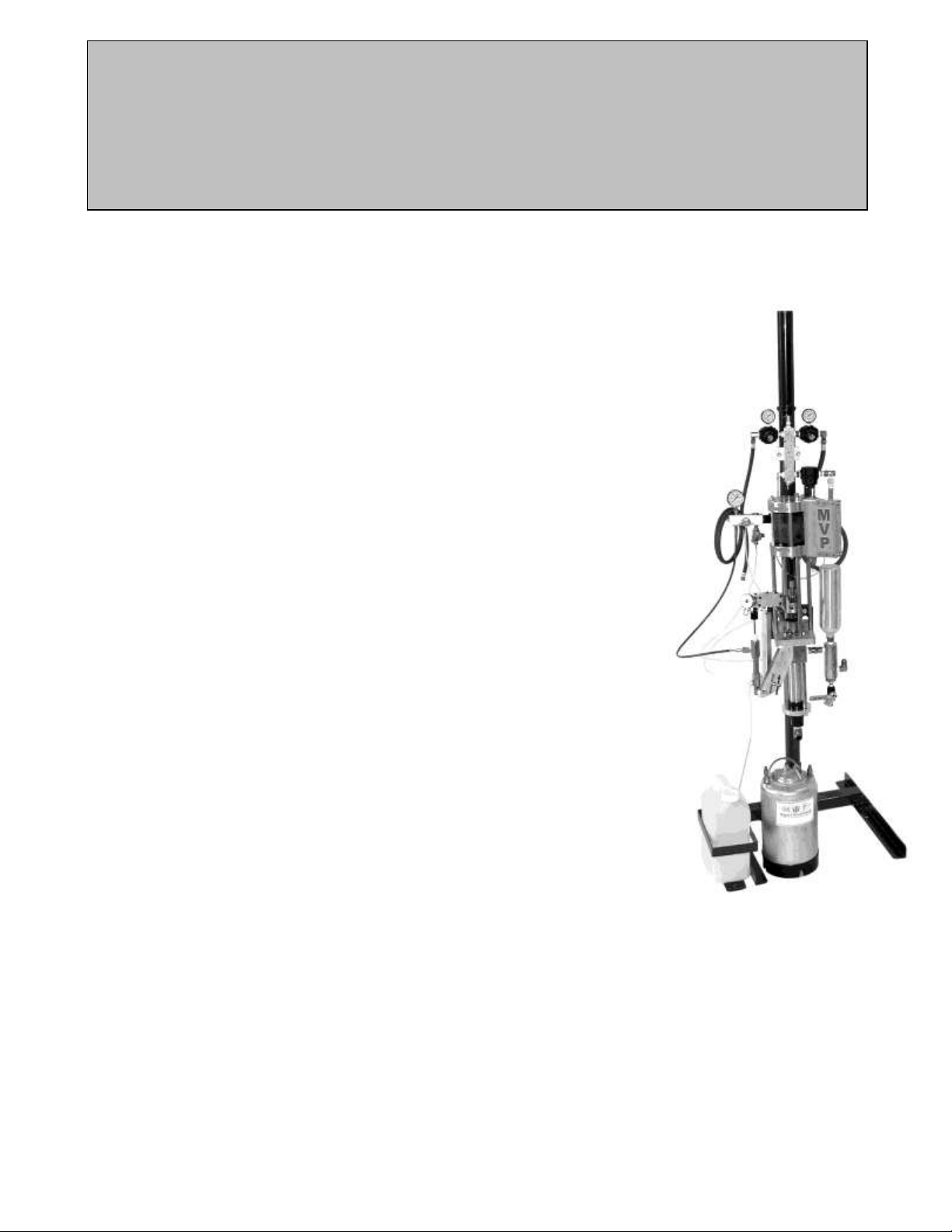
MVP - UltraMAX™
Installation & Set-Up
CHECKLIST
1. Check all clamp brackets, pump column, slave arm bracket, manifold
clamp, etc. to make sure they will not move when unit is in operation.
2. Check the mounting of catalyst pump to make sure clevis pins are
secure.
3. Make sure exhaust silencer is secured to the power cylinder of the
resin pump.
4. IMPORTANT: Snug up the packing nut at the top of the catalyst
pump approximately ¼ turn.
5. Snug up, tighten, the resin pump packing by inserting two rods into
the holes in the oil cup at the top of the resin pump fluid section.
Turn clockwise until packing is snug. Note: Do not over tighten.
6. ProGun: Tighten the gun valve rod packing nuts until they are very
snug. IMPORTANT: Activate the gun trigger 10 - 15 times then
tighten the packing nuts. Repeat this tightening procedure 3 times
to make sure the gun valve rod packing is tight.
7. Attach Suction Wand to Resin Pump.
a. Check all fittings on the wand assembly to make sure they are
airtight.
b. Attach the wand assembly to the foot valve port of the resin
pump.
8. Hose connections.
a. Connect the black resin hose from the gun to the outlet fitting on
the resin filter.
b. Connect the catalyst hose from the catalyst pump to the inlet of the catalyst manifold.
c. Connect the catalyst hose from the gun to the outlet of the catalyst manifold assembly.
d. Attach the red air hose from the gun to the fitting on the regulator labeled gun.
e. Attach the yellow poly flush hose from the gun to the outlet fitting of the solvent tank.
f. Attach the small red air supply hose from the flush regulator to the input fitting on the solvent
tank.
g. Attach the large red air hose from the pump regulator to the power cylinder of the resin pump.
Note: Check all hose fittings and fluid connections to make sure they are tight.
Page 2

h. Attach the ground wire from the gun to the electrical grounding lug on the pump mounting
Corporate Headquarters/Manufacturing
5148 113th Ave.
Clearwater, FL 33760 USA
Ph: (727) 573-2955
Fax: (727) 571-3636
MVP Technology Center
1862 Ives Ave.
Kent, WA 98032 USA
Ph: (253) 854-2660
Fax: (253) 854-1666
E-mail: info@mvpind.com · Web: www.mvpind.com
bracket.
Note: Check electrical ground to ensure it is installed from the pump mounting bracket to an
earth ground.
i. Remove the catalyst poly tubes from the component box.
j. Cut the ½ inch diameter poly line, with the clamps, to 26 inches long. Clamp one end to the
outlet of the catalyst jug and the other end to the inlet of the catalyst pump. Make sure clamps
are airtight.
k. Connect the ¼-inch poly line to the relief valve on the catalyst manifold assembly and insert
the other end into the hole in the top of the catalyst jug.
l. Connect the ¼-inch poly line to the catalyst recirculation valve on the catalyst manifold, and
insert the other end into the hole in the top of the catalyst jug.
9. Check all components for damage.
 Loading...