

Page 1
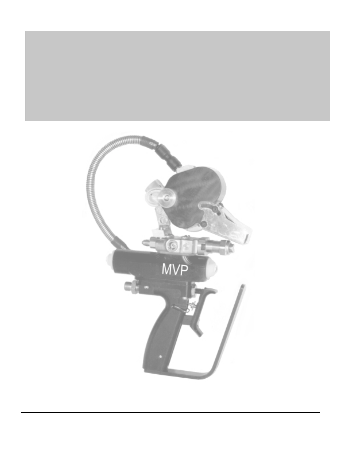
SUPER PRO GUN &
SUPER PRO GUN II
MAGNUM VENUS PRODUCTS
Maintenance & Repair Manual
Part No. M6707-1-1
Revision 04.14.01
SUPER PRO GUN &
SUPER PRO GUN II
Page 2

SUPER PRO GUN & SUPER PRO GUN II
Maintenance & Repair
Corporate HQ & Mfg.
Phone: (727) 573-2955
Fax: (727) 571-3636
Email: info@magind.com
Web: www .magind.com
© 2001 Magnum Venus Product s Manual Part No: M6707-1-1
SUPER PRO GUN &
SUPER PRO GUN II
Manufacturing
Phone: (253) 854-2660 (800) 448-6035
Fax: (253) 854-1666
Email: info@venusmagnum.com
Web: www .venusmagnum.com
Page 3

T able of Contents
SUPER PRO GUN & SUPER PRO GUN II
Maintenance & Repair
KNOW YOUR GUN
Repair Kits in Detail for Super Pro Gun & Super Pro Gun II
CHAPTER 1 - ASSEMBL Y INSTRUCTIONS
Assembly Instructions for Super Pro Gun II Actuator
CHAPTER 2 - ASSEMBL Y INSTRUCTIONS
Assembly Instructions for Super Pro Gun II Handle
CHAPTER 3 - ASSEMBL Y INSTRUCTIONS
Assembly Instructions for Super Pro Gun II Block
CHAPTER 4 - ASSEMBL Y INSTRUCTIONS
Assembly Instructions for Super Pro SuperCutter
CHAPTER 5 - DISASSEMBL Y INSTRUCTIONS
Disassembly Instructions for Super Pro Gun II Actuator
CHAPTER 6 - DISASSEMBL Y INSTRUCTIONS
Disassembly Instructions for Super Pro Gun II Handle
CHAPTER 7 - DISASSEMBL Y INSTRUCTIONS
Disassembly Instructions for Super Pro Gun II Block
CHAPTER 8 - DISASSEMBL Y INSTRUCTIONS
Disassembly Instructions for Super Pro SuperCutter
CHAPTER 9 - ASSEMBL Y DRAWINGS
SUPER PRO GUN &
SUPER PRO GUN II
Page 4
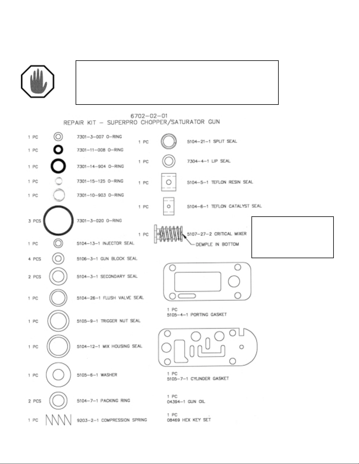
SUPER PRO GUN Repair Kit
NOTE
T o order the correct repair kit, refer to the gun handle before ordering parts.
NOTE
A Turbulent Mixer is not used
in FIT™ configurations.
SUPER PRO GUN &
SUPER PRO GUN II
Page 5
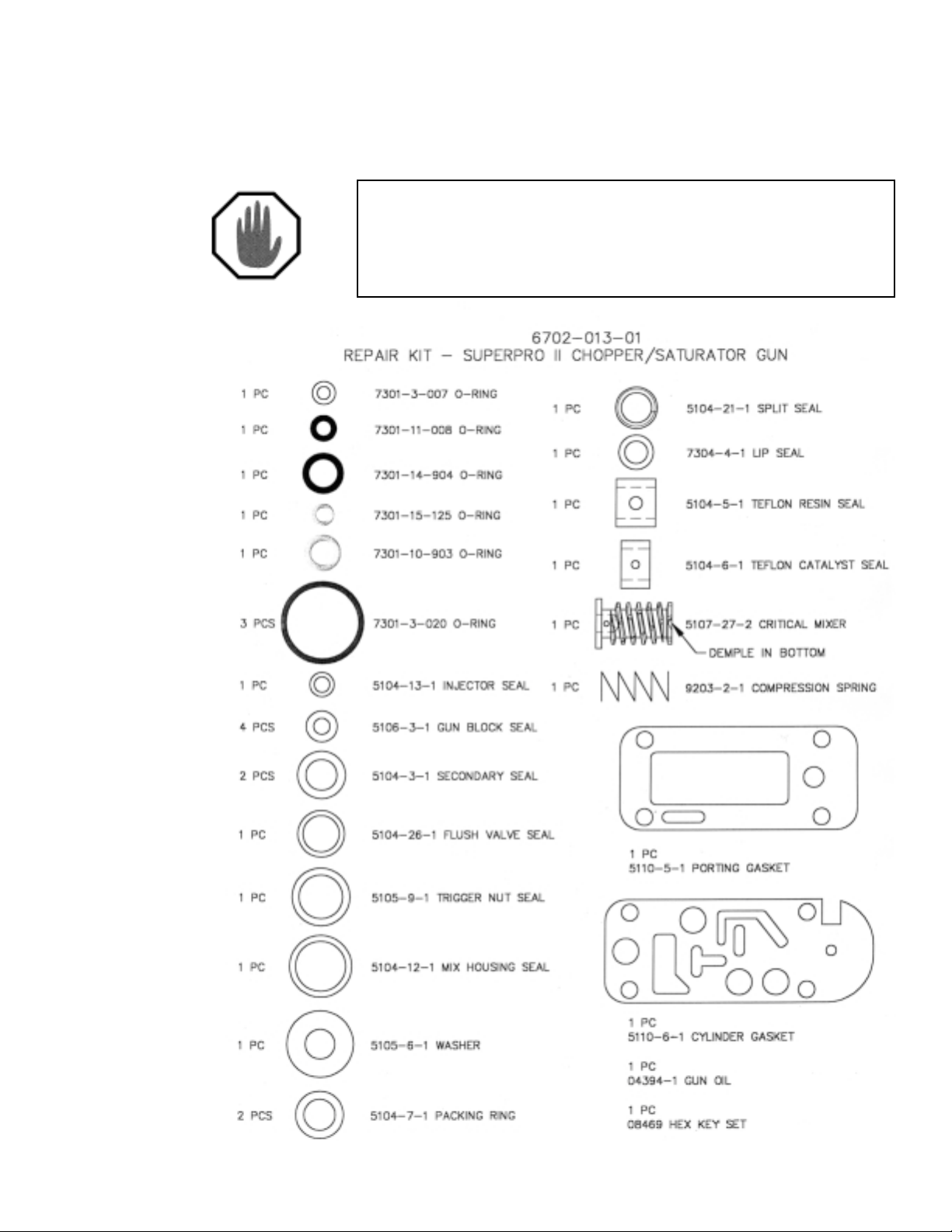
SUPER PRO GUN II Repair Kit
NOTE
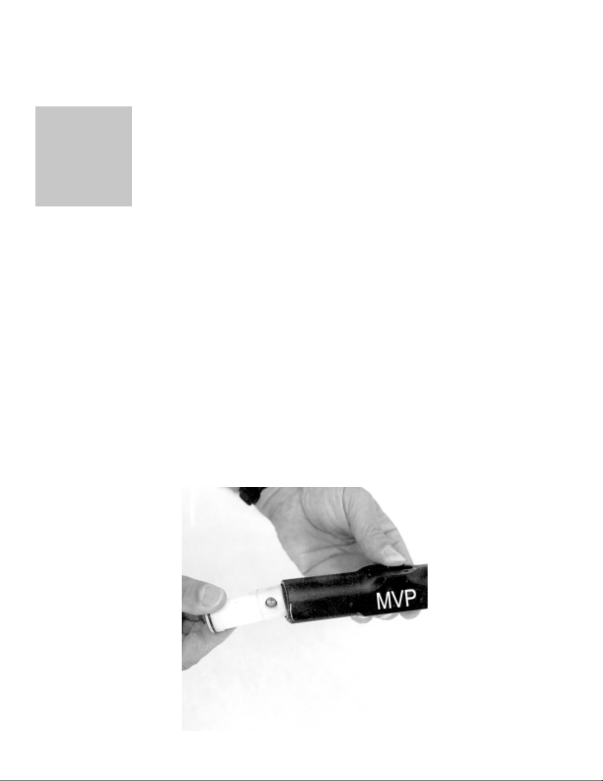
The Super Pro Gun II is identified by either the blue handle or (on earlier
versions) by the #2 stamped on the handle side.
SUPER PRO GUN &
SUPER PRO GUN II
Page 6
Chapter
1
SUPER PRO GUN
Actuator Assembly 5106-01-01
See Figs. 9.1 & 9.2 for exploded schematic drawings
1. Install the 7301-3-020 (O-Ring) onto the 5106-7-1 (Actuator
Piston) and the two 5106-4-1 (Cylinder Caps)
2. Using 6706-3-1 (Pro Gun Oil), lightly coat the Inside of the
5106-1-01 (Cylinder Body) and the 5106-7-1 (Actuator Piston).
3. Install the 5106-5-1 (Actuator Bushing) into the 5106-7-1 (Actuator
Piston).
4. Push the 5106-7-1 (Actuator Piston) into the 5106-1-01 (Cylinder
Body) through the long end. See Fig. 1.1
Fig. 1.1
SUPER PRO GUN &
SUPER PRO GUN II
1
Page 7

NOTE
The Piston should be inserted “bushing end first”, with the bushing on the top
side of center.
5. Install the two 5106-4-1 (Cylinder Caps).
6. Place the 5106-2-1 (Actuator Seal) over the 5106-1-01 (Cylinder Body)
so the Mounting screw holes line up.
7. Place the 5104-00-01 (Gun Block Assembly) onto the 5106-2-1 (Actuator
Seal.
NOTE
The 5104-11-1 (Actuating Stem) must be inserted into the 5106-5-1
(Bushing) located in the 5106-7-1 (Actuating Piston).
8. Secure the 5104-00-01 (Gun Block Assembly) onto the 5106-01-01 (Gun
Actuator) with the four 5106-6-1 (Mounting Screws) and the 5106-3-1
(Mounting Seals).
2
SUPER PRO GUN &
SUPER PRO GUN II
Page 8

Chapter
2
SUPER PRO GUN
Handle Assembly
See Figs. 9.3 & 9.4 for exploded schematic drawings
1. Carefully install the 5105-9-1 (Trigger Nut Seal) over the
5105-10-1 (Trigger Nut).
2. Coat the 7304-4-1 (Lip Seal) with 6706-3-1 (Pro Gun Oil), and
push it into the 5105-10-1 (Trigger Nut).
Once in place the spring of the 7304-4-1 (Lip Seal) should be facing out.
3. Screw the 5105-10-1 (Trigger Nut) into the 5105-1-1 (Gun Handle),
and tighten. Coat the 5105-14-1 (Trigger S tem) with 6706-3-1 (Pro
Gun Oil) and install from the inside cavity of the 5105-1-1 (Gun
Handle) through the 5101-10-1 (Trigger Nut).
4. Place the 5105-15-01 (Pivot Plate) into the slot in the
5105-1-1 (Gun Handle Assembly), and push the 7203-4-9 (Slotted
Spring Pin) located on the back side of the 5105-16-1 (Trigger) into
the hole in the 5105-14-1 (Trigger S tem). Line up the 5105-15-2
(Pivot Plate Bushing) to the lower pivot hole in the Gun Handle,
insert the 7102-10-12 (Slotted Flat Head Screw) and tighten.
5105-00-01
NOTE
When installing the Trigger Assembly the 5105-8-1 (Trigger Lock) must be in
the “down” position.
SUPER PRO GUN &
SUPER PRO GUN II
NOTE
3
Page 9

5. Set the 9203-2-1 (Compression Spring) into the spring seat
located in the upper cavity of the 5105-1-1 (Gun Handle).
6. Place the small pinhole in the 5105-3-1 (Slide Valve) over the pin
through the 5105-14-1 (Trigger Stem), and push down
compressing the spring into the handle cavity.
7. Place the 5105-4-1 (Porting Plate Gasket) over the screws,
matching the slot to the slot in the 5105-1-1 (Gun Handle).
8. Lightly lubricate the flat side of the 5105-5-1 (Porting Plate) with
6706-3-1 (Pro Gun Oil) and push it over the 5105-3-1 (Slide Valve)
keeping the Slide Valve connected to the 7203-4-9 (Slotted Spring
Pin) in the 5105-14-1 (Trigger S tem).
NOTE
The slot in the side of the 5105-5-1 (Porting Plate) must line up with the slot
in the 5105-1-1 (Gun Handle).
9. Set the 5105-6-1 (Toggle W asher) into the washer seal seat of the
5105-5-1 (Porting Plate) large side down.
10. Set the 5105-7-1 (Cylinder Gasket) over the screws, matching the
slots in the 5105-5-1 (Porting Plate)
11. Carefully position the 5106-00-01 (Gun Actuator Assembly) over
the 5105-00-01 (Gun Handle Assembly) and fasten with the two
5105-12-1 (Front Screws) and the 5105-13-1 (Rear Screws).
12. If necessary , adjust the 5105-8-1 (T rigger Lock) by pulling the
5105-16-1 (Trigger) to “full out”, then flip the T rigger Lock up until it
hits the smallest part of the 5105-11-1 (T rigger Lock Screw).
Loosen the 7102-6-4 (Socket Cup Point Set Screw) and adjust the
Trigger Lock Screw until it clears with minor interference. The locking
legs on the T rigger Lock Screw must be vertical. The T rigger Lock
should lock the trigger in both the open and closed position. Once
adjusted, tighten the 7102-6-4 (Socket Cup Point Set Screw).
13. With the two 7102-8-8 (Slotted Pan Head Screws), mount the
5105-2-1 (Trigger Guard).
SUPER PRO GUN II
Handle Assembly 5110-7-1
See Figs. 9.5 & 9.6 for exploded schematic drawings
1. Carefully install the 5105-9-1 (Trigger Nut Seal) over the
5105-10-1 (Trigger Nut).
2. Coat the 7304-4-1 (Lip Seal) with 6706-3-1 (Pro Gun Oil), and
push it into the 5105-10-1 (Trigger Nut).
4
SUPER PRO GUN &
SUPER PRO GUN II
Page 10

NOTE
Once in place the spring of the 7304-4-1 (Lip Seal) should be facing out.
3. Screw the 5105-10-1 (Trigger Nut) into the 5110-7-1 (Gun Handle)
and tighten. Coat the 5110-4-1 (trigger stem) with 6706-3-1 (Pro
Gun Oil) and install from the inside cavity of the 5110-7-1 (Gun
Handle) through the 5105-10-1 (trigger nut).
4. Place the 5105-15-01 (Pivot Plate) into the slot in the
5110-7-1 (Gun Handle Assembly), and push the 7203-4-10
(Slotted Spring Pin) located on the backside of the 5105-16-1
(Trigger) into the hole in the 5110-4-1 (T rigger S tem). Line up the
5105-15-2 (Pivot Plate Bushing) to the lower pivot hole in the Gun
Handle, insert the 7102-10-12 (Slotted Flat Head Screw) and
tighten.
NOTE
When installing the Trigger Assembly the 5105-8-1 (Trigger Lock) must be in
the “down” position. Y ou may find it easier to assemble the gun handle by
placing the flats at the back of the 5110-7-1 (Gun Handle) in a vise. This will
support the rear screws (5105-13-1) from pushing down during assembly.
5. Set the 9203-2-1 (Compression Spring) into the spring seat
located in the upper cavity of the 5110-7-1 (Gun Handle).
NOTE
For 2-stage chopper only.
Set the 5110-3-1 (two position gun detent plate) over the 9203-2-1
(Compression Spring). The elevated shoulder of the 5110-3-1
(two position detent plate) faces up.
6. Place the small pinhole in the 5110-2-1 (Slide Valve) over the pin
through the 5110-4-1 (Trigger Stem), and push down
compressing the spring into the handle cavity.
7. Place the 5110-5-1 (Gun Handle Gasket) over the screws,
matching the slot to the slot in the 5110-7-1 (Gun Handle).
8. Lightly lubricate the topside of the 5110-1-1 (Porting Plate) with
6706-3-1 (Pro Gun Oil) and push it over the 5110-2-1 (Slide Valve)
keeping the Slide Valve connected to the 7203-4-9 (Slotted Spring
Pin) in the 5110-4-1 (Trigger Stem).
SUPER PRO GUN &
SUPER PRO GUN II
5
Page 11

NOTE
The slot in the side of the 5110-1-1 (Porting Plate) must line up with the slot
in the 5110-7-1 (Gun Handle).
9. Set the 5105-6-1 (Toggle W asher) into the washer seal seat of the
5110-1-1 (Porting Plate) large side down.
10. Set the 5110-6-1 (Cylinder Gasket) over the screws, matching the
slots in the 5110-1-1 (Porting Plate)
11. Carefully position the 5106-00-01 (Gun Actuator Assembly) over
the 5110-7-1 (Gun Handle Assembly) and fasten with the two
5105-12-1 (Front Screws) and the 5105-13-1 (Rear Screws).
12. If necessary , adjust the 5105-8-1 (T rigger Lock) by pulling the
5105-16-1 (Trigger) to “full out”, then flip the T rigger Lock up until it
hits the smallest part of the 5110-8-1 (T rigger Lock Screw).
Loosen the 7102-6-4 (Socket Cup Point Set Screw) and adjust the
Trigger Lock Screw until it clears with minor interference. The
locking legs on the Trigger Lock Screw must be vertical. The
Trigger Lock should lock the trigger in both the open and closed
position. Once adjusted, tighten the 7102-6-4 (Socket Cup Point
Set Screw).
13. With the two 7102-8-8 (Slotted Pan Head Screws), mount the
5105-2-1 (Trigger Guard).
6
SUPER PRO GUN &
SUPER PRO GUN II
Page 12

Chapter
3
SUPER PRO GUN
Gun Block Assembly
See Figs. 9.9 - 9.12 for exploded schematic drawings
Flush V alve Assembly
1. Install the 7301-11-008 (O-Ring) onto the 5104-25-1(Flush Valve
Button).
2. Install the 7301-3-007 (O-Ring) onto the 5104-23-1 (Flush Seal
Body).
3. Install the 9203-2-3 (Compression Spring) into the 5104-24-1
(Flush Valve Body).
4. Smear 6706-2-1 (White Grease) onto the 5104-25-1 (Flush V alve
Button), and the 5104-23-1 (Flush Seal Body). Thread the Flush
Valve Button through the 9203-2-3 (Compression Spring) located
in the 5104-24-1 (Flush Valve Body), and screw on and tighten the
Flush Seal Body.
5. Install the 5104-26-1 (Flush Valve Seal) onto the 5104-24-1 (Flush
V alve Body) and thread through the 5104-22-1 (Flush Valve Neck).
6. Install the 5104-02-01 (Flush Elbow Assembly) onto the
5104-22-1 (Flush Valve Neck).
7. Install the 5104-21-1 (Flush Valve Split Seal) onto the 5104-24-1
(Flush V alve Body).
5104-00-01
SUPER PRO GUN &
SUPER PRO GUN II
7
Page 13
Gun Block Assembly
1. Check for and remove debris and burrs in 5104-1-1 (Gun Block).
2. Install the two 5104-3-1 (Secondary Seals) in the 5104-1-1 (Gun
Block). See Fig. 3.1
Fig. 3.1
3. Install the 5104-10-1 (Center Spacer) into the center area of the
5104-1-1 (Gun Block).
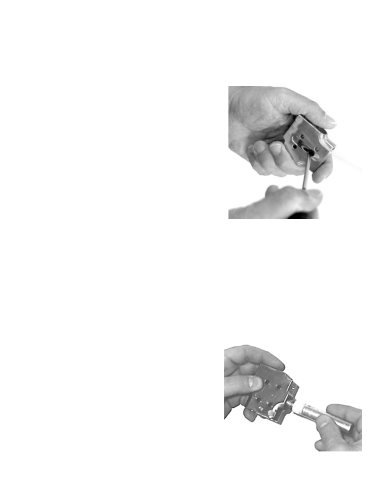
4. Insert the 9301-5-1 (Seal Installation Tool) through the side of the
gun block to align the 5104-10-1 (Center Spacer) with the
5104-3-1 (Secondary Seals).
5. Install the catalyst seal components onto the 9301-5-1 (Seal
Installation Tool) in the following order; 5104-7-1 (Packing Ring),
5104-6-1 (Teflon Catalyst Seal), and the 5104-4-1 (Relief Spacer).
See Fig. 3.2.
6. Insert the Seal Installation Tool with the catalyst seal components
into the catalyst port of the 5104-1-1 (Gun Block) See Fig. 3.2.
Fig. 3.2
8
SUPER PRO GUN &
SUPER PRO GUN II
Page 14
NOTE
Before inserting the Seal Alignment T ool, align the holes in the 5401-6-1
(T eflon Catalyst Seal) with the holes in the 5104-1-1 (Gun Block) as closely
as possible.
7. Press firmly , or t ap with a hammer until the seal assembly bottoms
out in the 5104-1-1 (Gun Block), then gently remove the Seal
Installation Tool.
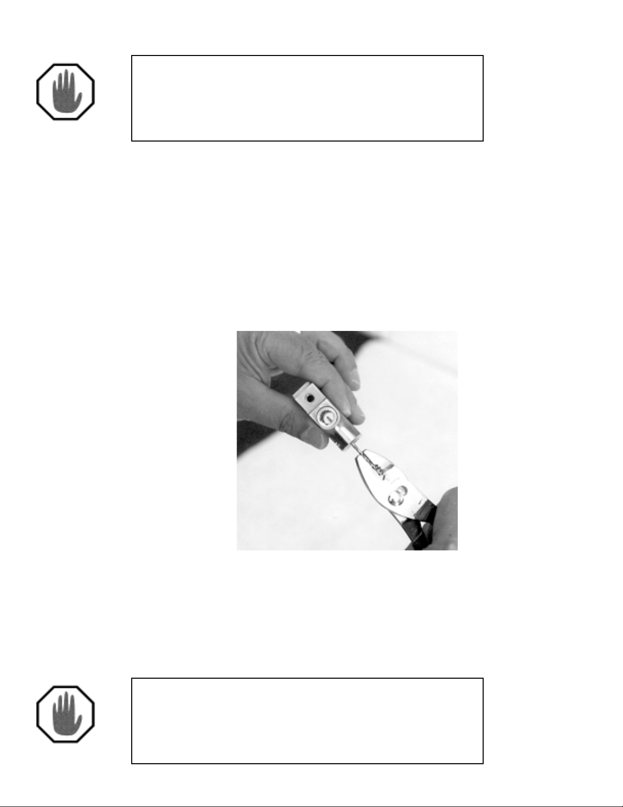
8. Hold the 9301-4-1 (Catalyst Seal Alignment Tool) firmly with a pair
of pliers.
9. Insert the tapered end of the 9301-4-1 (Catalyst Seal Alignment
Tool), into the 5104-1-1 (Gun Block) through the catalyst fitting port
on the back of the Gun Block.
10. Gently press and move the Seal Alignment Tool around until the
holes in the 5104-6-1 (Teflon Catalyst Seal) align with the catalyst
port in the 5104-1-1 (Gun Block) See Fig. 3.3.
Fig. 3.3
11. Install and hand tighten the 5104-8-1 (Packing Nut).
12. Install the resin seal components into the 9301-5-1 (Seal
Installation Tool) in the following order: 5104-7-1 (Packing Ring),
5104-5-1 (Teflon Resin Seal), and the 5104-4-1 (Relief Spacer).
See Fig. 3.4.
13. Insert the Seal Installation Tool into the resin port of the 5104-1-1
(Gun Block) See Fig. 3.4.
Before inserting the Seal Alignment T ool, align the holes in the 5401-5-1
(T eflon Resin Seal) with the holes in the 5401-1-1 (Gun Block) as closely
as possible.
SUPER PRO GUN &
SUPER PRO GUN II
NOTE
9
Page 15
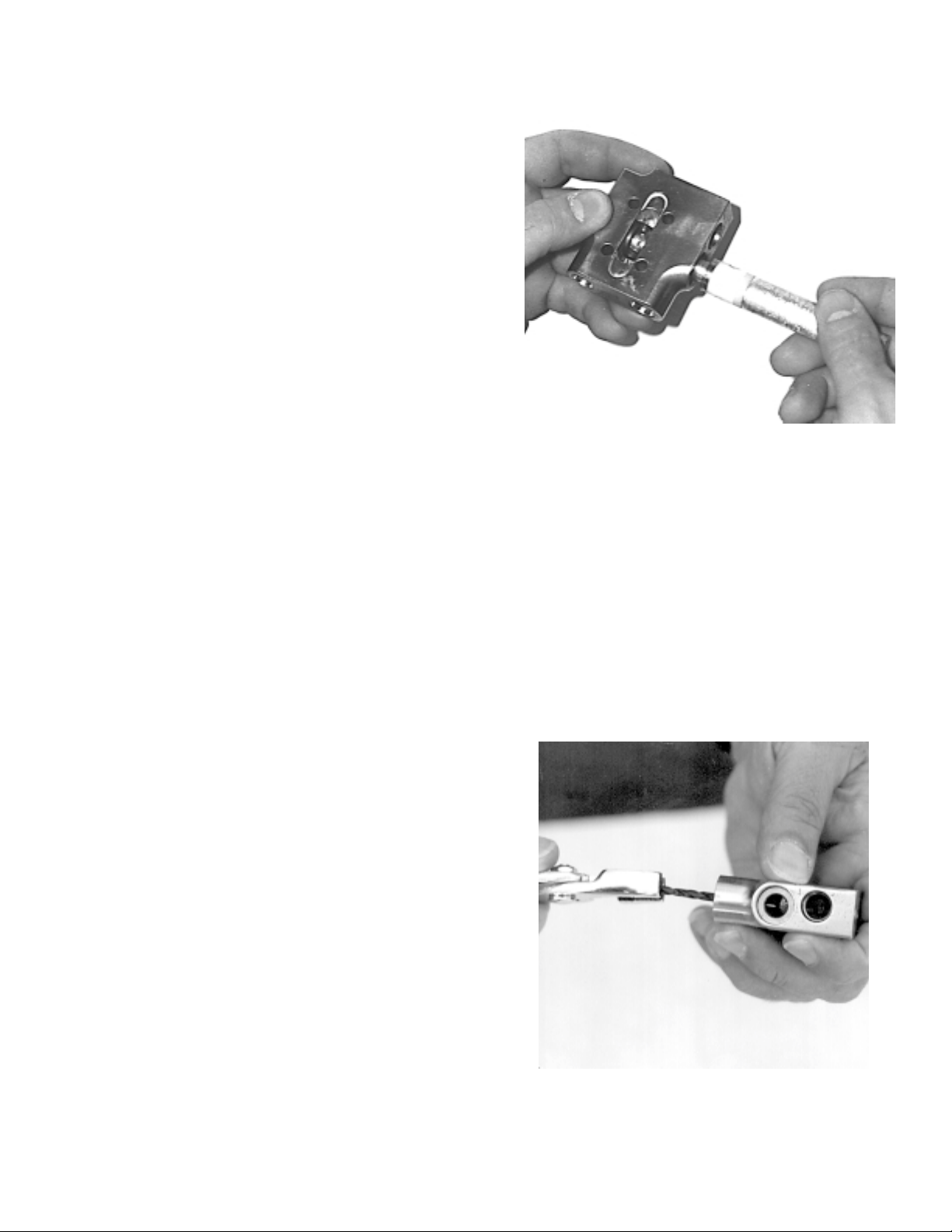
Fig. 3.4
14. Press firmly , or t ap with a hammer until the seal assembly bottoms
out in the 5104-1-1 (Gun Block), then gently remove the Seal
Alignment T ool.
15. Hold the 9301-4-2 (Resin Seal Alignment Tool) firmly with a pair of
pliers.
16. Insert the tapered end of the 9301-4-2 (Resin Seal Alignment
Tool), into the 5104-1-1 (Gun Block) through the resin fitting port
on the back of the Gun Block.
17. Gently press and move the Seal Alignment Tool around until the
holes in the 5104-5-1 (Teflon Resin Seal) align with the resin port
in the 5104-1-1 (Gun Block). See Fig. 3.5
Fig. 3.5
10
SUPER PRO GUN &
SUPER PRO GUN II
Page 16
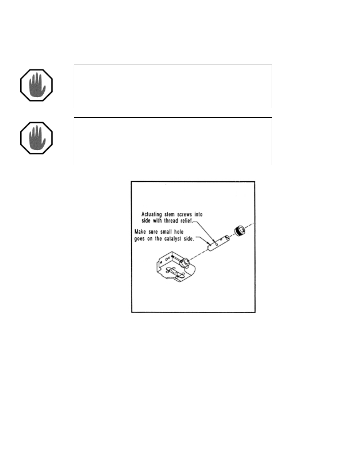
18. Install the 5104-2-1 (V alve Rod) through the resin side of the gun.
Use the 9301-5-1 (Seal Installation Tool) to center the V alve Rod
in the 5104-1-1 (Gun Block).
NOTE
Make sure that the Valve Rod is correctly aligned; the larger hole goes on the
resin side, while the smaller hole goes on the catalyst side. See Fig. 3.6.
NOTE
The middle hole, into which the actuating stem will be inserted, must also be
correctly aligned. One end of the hole has a relief in the threads, which
should face down. See Fig. 3.6.
Fig. 3.6
19. Install and hand tighten the 5104-8-1 (Packing Nut) onto the resin
side of the 5401-1-1 (Gun Block).
SUPER PRO GUN &
SUPER PRO GUN II
11
Page 17
20. Install the 5104-11-1 (Actuating S tem) into the 5104-2-1 (Valve
Rod).
NOTE
Use removable strength thread locking compound on Actuating Stem threads.
21. Actuate the 5104-1 1-1 (Valve Stem) back and forth 3 or 4 times,
then snug both 5104-8-1 (Packing Nuts) with 9301-2-3 (Packing
Bit) until firm. Again, actuate the Valve Stem back and forth 3 or 4
times.
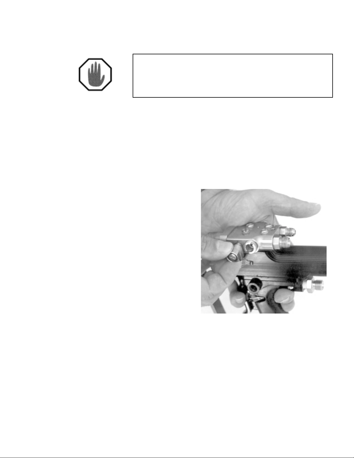
22. Install the 5104-32-1 (Plug), and the 7301-15-125 (O-Ring) in the
port provided on the catalyst side of the 5104-1-1 (Gun Block).
23. Install the 5104-32-1 (Plug) into the flush port on the resin side of
the 5104-1-1 (Gun Block). See Fig. 3.7
Fig. 3.7
24. Install the 5104-27-1 (Catalyst Fitting), and the 7301-10-903
(O-Ring) onto the 5104-1-1 (Gun Block).
25. Install the 5104-9-1 (Resin Fitting) and the 7301-14-904 (O-Ring)
onto the 5104-1-1 (Gun Block).
26. Insert the 5104-03-01 (Injector Assembly) and 5104-17-1
(Distribution Ring) into the 5104-20-1 (Mix Housing).
12
SUPER PRO GUN &
SUPER PRO GUN II
Page 18

27. Position the 5104-12-1 (Mix Housing Seal) onto the backside of
the 5104-20-1 (Mix Housing). See Fig. 3.8.
Fig. 3.8
28. Using the two 7102-1-6 (Socket Head Cap Screws), mount the
5104-20-1 (Mix Housing) onto the 5104-1-1 (Gun Block).
SUPER PRO GUN &
SUPER PRO GUN II
13
Page 19

Chapter
4
SUPER PRO GUN
SuperCutter Assembly 5101-01-01
See Figs. 9.13 - 9.20 for exploded schematic drawings
NOTE
The sharp edge of the Chopper Blades should be slightly dulled by stropping
them on cardboard prior to installation into Rotor Assembly. This intentional
dulling of the blades by the whetting process will avoid slicing and nicking of
the Rubber Roll and will assure longer life of both Blades and Rubber Roll.
See Fig. 4.1.
Fig. 4.1
14
SUPER PRO GUN &
SUPER PRO GUN II
Page 20

Rotor Assembly
1. Insert 9210-1-1 (Chopper Blades) between the 5103-28-1 (Rotor
Hub) and 5103-29-1 (Wedge Insert). The back edge of the Blade
must be bottomed against the Rotor Hub. See Fig. 4.2.
Fig. 4.2
2. Align the edges of the blade with the end of the 5103-28-1 (Rotor
Hub). Tighten the 7102-13-6 (Socket Flat Head Screw) in the
5103-29-1 (Wedge Insert) to secure the blades in place.
3. Wipe a small amount of grease on the 8402-1-1 (Air Motor) shaft.
4. Slide the 5103-03-01 (Wedge Rotor Assembly) onto the 8402-1-1
(Air Motor) shaft, so the 7102-14-6 (Set Screws) in the 5103-28-1
(Rotor Hub) ride on the flat of the chopper motor shaft.
NOTE
The rotor must be positioned on the Air Motor shaft so it aligns with the
Rubber Roll. See Fig. 4.3
SUPER PRO GUN &
SUPER PRO GUN II
15
Page 21

Fig. 4.3
Rubber Roll Assembly
5. Press the 5103-6-1 (Rubber Roll) onto the 5103-5-01 (Mandrel
Assembly). Secure the Rubber Roll by inserting the 7205-3-31
(E-Ring) into the groove in the Mandrel. See Fig. 4.4.
6. Insert the Mandrel/Rubber Roll Assembly into the top of the T-Slot
on the 5103-1-1 (Base Plate). Align the 5103-4-1 (Slide Adjust
Nut) with the T -Slot. See Fig. 4.5.
Fig. 4.4
16
Fig. 4.5
SUPER PRO GUN &
SUPER PRO GUN II
Page 22

7. Slide Rubber Roll Assembly toward the 5103-03-01 (Wedge Rotor
Assembly) and tighten the 7102-2-20 (Socket Head Cap Screw)
Rubber Roll Adjustment
1. Slightly loosen the 7102-2-20 (Socket Head Cap Screw), just
enough so the Rubber Roll Assembly will slide in the T-Slot. See
Fig. 4.6.
Fig. 4.6
2. Apply slight pressure of the Rubber Roll Assembly to the
5103-03-01 (Wedge Rotor Assembly), and tighten the 7102-2-20
(Socket Head Cap Screw).
NOTE
When making this adjustment, Rubber Roll must not be in contact with
Chopper Blade.
SUPER PRO GUN &
SUPER PRO GUN II
17
Page 23

Idler Adjustment
1. Slightly loosen the 7102-2-20 (Socket Head Cap Screw), just
enough so the Idler Assembly will slide in the T-Slot. See Fig. 4.7.
Fig. 4.7
2. Slide the 5103-7-01 (Sleeve w/ Bearing) until it just makes contact
with the 5106-6-1 (Rubber Roll).
NOTE
Proper adjustment has Idler Assembly touching the Rubber Roll, but still able
to rotate with minimum effort.
18
SUPER PRO GUN &
SUPER PRO GUN II
Page 24

Chapter
5
SUPER PRO GUN
Actuator Disassembly 5106-01-01
See Figs. 9.1 & 9.2 for exploded schematic drawings
1. Unscrew the two 5105-13-1 (Rear Screws), and the two 5105-12-1
(Front Screws) to remove the 5106-00-01 (Cylinder Body
Assembly) from the 5105-00-01 (Gun Handle Assembly).
2. Remove the two 5106-4-1 (Cylinder Caps) from the 5106-1-1
(Cylinder Body). Remove and discard the two 7301-3-020
(O-Rings) from the 5106-4-1 (Cylinder Caps).
3. Push the 5106-7-1 (Actuator Piston) out of the back of the
5106-1-1 (Cylinder Body). Remove and discard the 7301-3-020
(O-Ring) from the Actuator Piston.
NOTE
Discard all parts to be replaced by repair kit. All remaining parts should be
thoroughly cleaned, inspected for damage, and replaced if necessary.
SUPER PRO GUN &
SUPER PRO GUN II
19
Page 25

Chapter
SUPER PRO GUN
Handle Disassembly 5105-00-01
See Figs. 9.3 & 9.4 for exploded schematic drawings
1. Remove and discard the 5105-7-1 (Cylinder Gasket), and the
5105-6-1(Toggle Washer) from the 5105-5-1 (Porting Plate).
2. Remove the 5105-5-1 (Porting Plate) from the 5105-1-1 (Gun
Handle).
6
3. Remove the 5105-4-1 (Porting Plate Gasket),
5105-3-1 (Slide Valve), and the 9203-2-1 (Compression Spring)
from the 5105-1-1 (Gun Handle). Discard the Porting Plate Gasket
and Compression Spring.
4. Remove the two 7102-8-8 (Slotted Pan HD Mach Screws) to
remove the 5105-2-1 (Trigger Guard).
5. Remove 7102-10-12 (Slotted Flat Head Screw), and slide the
5105-16-01 (Trigger Assembly) out from under the 5105-14-1
(Trigger S tem).
6. Remove the 5105-10-1 (Trigger Nut) from the 5105-1-1 (Gun
Handle).
20
SUPER PRO GUN &
SUPER PRO GUN II
Page 26

7. Remove and discard the 5105-9-1 (Trigger Nut Seal), and the
7304-4-1 (Lip Seal) from the 5105-10-1 (Trigger Nut)
NOTE
Discard all parts to be replaced by repair kit. All remaining parts should be
thoroughly cleaned, inspected for damage, and replaced if necessary.
SUPER PRO GUN II
Handle Disassembly 5110-7-1
See Figs. 9.5 & 9.6 for exploded schematic drawings
1. Remove and discard the 5110-6-1 (Cylinder Gasket), and the
5105-6-1(Toggle Washer) from the 51 10-1-1 (Porting Plate).
2. Remove the 5110-1-1 (Porting Plate) from the 5110-7-1 (Gun Handle).
3. Remove the 5110-5-1 (Handle Gasket) and the 5110-2-1 (Slide Valve).
NOTE
For two stage trigger, chopper gun handle only. Remove the 5110-3-1
(Detent Plate).
Remove the 9203-2-1 (Compression Spring) from the 5110-7-1 (Gun
Handle). Discard the Gun Handle Gasket and Compression Spring.
4. Remove the two 7102-8-8 (Slotted Pan HD Mach Screws) to
remove the 5105-2-1 (Trigger Guard).
5. Remove 7102-10-12 (Slotted Flat Head Screw), and slide the
5105-15-01 (Pivot Plate) out from under the 5110-4-1
(Trigger S tem).
6. Remove the 5105-10-1 (Trigger Nut) from the 5110-7-1 (Gun Handle).
7. Remove and discard the 5105-9-1 (Trigger Nut Seal), and the
7304-4-1 (Lip Seal) from the 5105-10-1 (Trigger Nut)
Discard all parts to be replaced by repair kit. All remaining parts should be
thoroughly cleaned, inspected for damage, and replaced if necessary.
SUPER PRO GUN &
SUPER PRO GUN II
NOTE
21
Page 27

Chapter
7
SUPER PRO GUN
Gun Block Disassembly 5104-00-01
See Figs. 9.9 - 9.12 for exploded schematic drawings
1. Remove the four 5106-6-1 (Mounting Screws), and the four
5106-3-1 (Mounting Seals) to remove the 5104-00-01 (Gun Block
Assembly) from the 5106-00-01 (Gun Actuator Assembly).
2. Remove the two 7102-1-6 (Socket Head Cap Screws) to remove
the 5104-20-1 (Mix Housing) from the Gun Block Assembly.
3. Remove the 5104-12-1 (Mix Housing Seal), and the 5104-17-1
(Distribution Ring) from the 5104-20-1 (Mix Housing).
4. Remove the 5104-03-01 (Injector Assembly), from the Gun Block
Assembly.
5. Remove the 5104-32-1 (Plug) from the 5104-1-1(Gun Block).
6. Remove the 5104-32-1 (Plug), and the 7301-15-125 (O-Ring) from
the 5104-1-1 (Gun Block).
7. Remove the 5104-9-1 (Resin Fitting), and the (7301-14-904
(O-Ring) from the 5104-1-1 (Gun Block).
8. Remove the 7701-3-6 (Catalyst Fitting), and 7301-10-903
(O-Ring), from the 5104-1-1 (Gun Block).
9. Remove 5104-11-1 (Actuating Stem) from the 5104-2-1 (Valve
Rod).
10. Remove both 5104-8-1(Packing Nuts) from the 5104-1-1 (Gun
Block).
11. Gently tap the 5104-2-1 (Valve Rod) from Gun Block using the
9301-5-1 (Seal-Installation Tool).
12. Remove 5104-10-1 (Center Spacer).
22
SUPER PRO GUN &
SUPER PRO GUN II
Page 28

13. Using the 9301-5-1 (Seal Installation Tool), force the Seal
Assembly out of the Gun Block.
NOTE
Seal Assembly consists of; two 5104-7-1 (Packing Rings), two 5104-4-1
(Relief Spacers), two 5104-3-1 (Secondary Seals), One 5104-6-1 (T eflon
Catalyst Seal), and one 5104-5-1 (T eflon Resin Seal).
Flush Valve Disassembly Procedures:
1. Remove and discard the 5104-21-1 (Flush Valve Split Seal) from
the 5104-24-1 (Flush Valve Body).
2. Remove the 5104-02-01 (Flush Elbow Assembly) from 5104-22-1
(Flush Valve Neck).
3. Remove the 5104-22-1 (Flush Valve Neck) and 5104-26-1 (Flush
V alve Seal) from the 5104-24-1 (Flush Valve Body). Discard the
5104-26-1 (Flush Valve Seal).
4. Remove the 5104-23-1 (Flush Seal Body) from the 5104-25-1
(Flush V alve Button).
5. Remove the 9203-2-3 (Compression Spring) from the
5104-24-1(Flush Valve Body).
6. Remove and discard the 7301-3-007 (O-Ring) from the 5104-23-1
(Flush Seal Body).
7. Remove and discard the 7301-11-008 (O-Ring) from the
5104-25-1 (Flush V alve Button).
Discard all parts to be replaced by repair kit. All remaining parts should be
thoroughly cleaned, inspected for damage, and replaced if necessary.
SUPER PRO GUN &
SUPER PRO GUN II
NOTE
23
Page 29

SUPER PRO GUN
SuperCutter Disassembly
5103-00-01
See Figs. 9.13 - 9.20 for exploded schematic drawings
1. Unscrew the 5103-14-1 (Cover Nut) and remove the 5103-13-1
(Chopper Cover) from the 5103-00-01 (Roving Cutter Basic
Assembly).
Chapter
8
The remainder of the disassembly covered in this manual pertains to
the rubber roll and the rotor.
Rubber Roll Disassembly
2. To remove the Rubber Roll Assembly, loosen the 7102-2-20
(Socket Cap Screw) enough to slide the 5103-4-1 (Slide Adjust
Nut) from the slot in the 5301-1-1 (Base Plate)
3. With a screw Driver, remove the 7205-3-31 (E-Ring), and slide the
5103-6-1 (Rubber Roll) off the 5403-5-01 (Mandrel Assembly).
24
SUPER PRO GUN &
SUPER PRO GUN II
Page 30

Rotor Disassembly
4. Loosen the two 7102-14-6 (Socket Cup Point Set Screws), and
slide the 5103-03-01 (8-Blade Rotor Assembly) off of the 8402-1-1
(Air Motor) shaft.
NOTE
Be very careful when handling the Rotor Assembly as the blades are sharp and
could cause injury.
5. Loosen the 7102-13-6 (Socket Flat Head Screws) used to secure
the 5103-29-1 (Wedge Inserts), and remove the 9210-1-1
(Chopper Blades) from the 5103-03-01 8-Blade Wedge Rotor
Assembly)
SUPER PRO GUN &
SUPER PRO GUN II
25
Page 31

SUPER PRO GUN &
SUPER PRO GUN II
Assembly Drawings
Chapter
9
26
SUPER PRO GUN &
SUPER PRO GUN II
Page 32

Fig. 9.1
SUPER PRO GUN &
SUPER PRO GUN II
27
Page 33

Fig. 9.2
28
SUPER PRO GUN &
SUPER PRO GUN II
Page 34

Fig. 9.3
SUPER PRO GUN &
SUPER PRO GUN II
SUPER PRO GUN
29
Page 35

Fig. 9.4
30
SUPER PRO GUN &
SUPER PRO GUN II
Page 36

Fig. 9.5
SUPER PRO GUN II
SUPER PRO GUN &
SUPER PRO GUN II
31
Page 37

Fig. 9.6
32
SUPER PRO GUN &
SUPER PRO GUN II
Page 38

Fig. 9.7
SUPER PRO GUN &
SUPER PRO GUN II
33
Page 39

Fig. 9.8
34
SUPER PRO GUN &
SUPER PRO GUN II
Page 40

Fig. 9.9
SUPER PRO GUN &
SUPER PRO GUN II
35
Page 41

Fig. 9.10
36
SUPER PRO GUN &
SUPER PRO GUN II
Page 42

Fig. 9.11
SUPER PRO GUN &
SUPER PRO GUN II
37
Page 43

Fig. 9.12
38
SUPER PRO GUN &
SUPER PRO GUN II
Page 44

Fig. 9.13
NOTE
These wedge rotors will not fit on the old style
“classic” pro gun choppers (58605-1). They are
for SuperPro and SuperPro II chopper
configurations. Please use the following part
numbers for rotors: 77730-1 (6 blade) or
77731-1 (8 blade).
SUPER PRO GUN &
SUPER PRO GUN II
39
Page 45

Fig. 9.14
40
SUPER PRO GUN &
SUPER PRO GUN II
Page 46

Fig. 9.15
SUPER PRO GUN &
SUPER PRO GUN II
41
Page 47

Fig. 9.16
42
SUPER PRO GUN &
SUPER PRO GUN II
Page 48

Fig. 9.17
SUPER PRO GUN &
SUPER PRO GUN II
43
Page 49

Fig. 9.18
44
SUPER PRO GUN &
SUPER PRO GUN II
Page 50

Fig. 9.19
SUPER PRO GUN &
SUPER PRO GUN II
45
Page 51

Fig. 9.20
46
SUPER PRO GUN &
SUPER PRO GUN II
Page 52

Fig. 9.21
SUPER PRO GUN &
SUPER PRO GUN II
47
Page 53

Fig. 9.22
48
SUPER PRO GUN &
SUPER PRO GUN II
Page 54

SUPER PRO GUN &
SUPER PRO GUN II
Page 55

SUPER PRO GUN &
SUPER PRO GUN II
Page 56

Corporate HQ & Mfg.
5148 1 13th Ave.
Clearwater, FL 33760 · USA
Phone: (727) 573-2955
Fax: (727) 571-3636
SUPER PRO GUN &
SUPER PRO GUN II
Manufacturing/Sales
1862 Ives A ve.
Kent, WA 98032 · USA
Phone: (253) 854-2660 (800) 448-6035
Fax: (253) 854-1666
Email: info@mvpind.com · Web: www .mvpind.com
© 2003 Magnum Venus Product s Manual Part No: PRO-MGS-22
 Loading...