

Page 1
PVSensor
Complete System # 5801
Procedure for Installation and Use
The PVSensor (PVS) system is designed to safely optimise LRTM or RTM mould fill. It is now possible to
monitor and control the in-mould pressure from 800mb to 2000mb. (The short term, safe over-pressure is
rated at 3 bar).
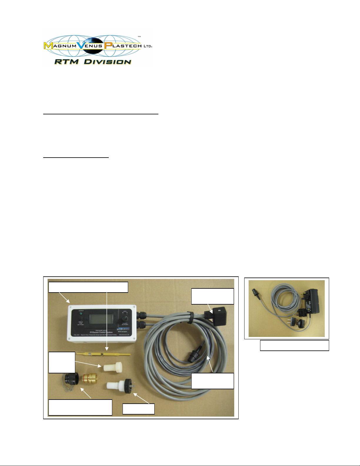
The system comprises:
• Electronic Display Module # 5798 – Operator controls and status LED
• Power Supply Unit # 5799 - 240/110vAC input, 12vDC output
• PVSensor # 5797 - A PTFE bodied precision electronic pressure sensor to fit a mould insert.
• Machine Control # 5789 - Output solenoid to control the resin flow of meter mix machinery.
Kit contains complete mounting bracket set and conversion fittings for Patriot SSB and
Megaject MkIV / MkV machines.
• Universal Insert with spring Clip # 6316, and Adapter # 6317
ELECTRONIC DISPLAY MODULE AND POWER PACK:
The Electronic Module houses the circuitry that manages the signal from the PVSensor and allows the
setting of the required mould pressure set-point and hysterisis. It also provides Actual Pressure readings
from the sensor in the mb range. The scale is x 10, as individual millibar changes would be too rapid and
confusing to read. Therefore a reading of 101 is actually 1010 mb (101 x 10).
Electronic Module & Trimmer tool
PVSensor
Socket
Power Supply Unit ( PSU )
PVS
Dummy
Plug
Machine control
lead
Universal Mould Insert,
Spring Clip and adapter
PVSensor
PVSensor Instruction Manual. Issue-08 25/06/2008 Page 1 of 8
Page 2
RETRO FITTING THE ELECTRONIC MODULE TO YOUR MACHINE:
1.
2.
-
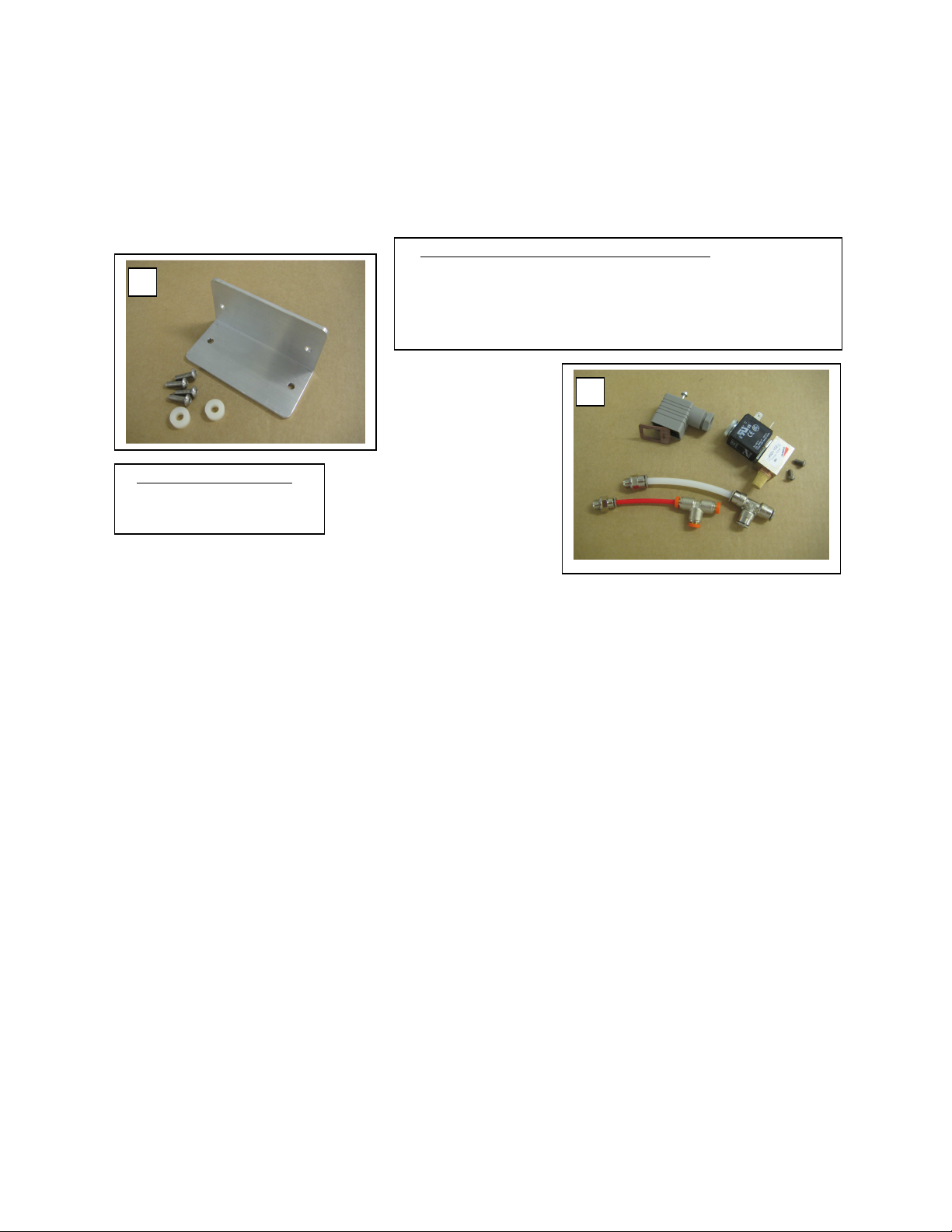
Retro Mounting Kit
.
1
2
If your PVSensor system was not factory fitted you will need to fit the mounting bracket and make some
minor changes to the machine’s air circuit. The PVSensor is supplied complete with, Machine Control
Solenoid Valve assembly # 5789, and fixing bracket, spacers and screws to mount the Electronic Module
to the SSB chassis, or the Megaject Cabinet. See Appendix A.1, A.2 and A.3 for full instructions.
Machine Control solenoid assembly # 5789 includes:
- Solenoid Socket.
- Solenoid Valve & silencer with mounting screws to SSB or MkIV / MkV.
- 6mm clear nylon pipe with Tee and stud fittings for SSB connection.
- 4mm red nylon pipe with Tee and stud fittings for MkIV & MkV connection.
Retro Mounting Kit includes:
Mounting Bracket, 4 x Bolts and
2 x Spacers.
CONNECTING THE ELECTRONIC MODULE TO THE MACHINE:
With the power switched OFF, connect the 12vDC PSU to the socket on the left hand end of the
Electronic Module.
Connect the 3 way, black socket to the injection machine plug now fitted as standard on all
standard Magnum Venus Plastech meter mix machines.
This plug can be found flush mounted on the side of older Megaject SSB model chassis, on the
rear of Patriot SSB chassis, or on the back of the yellow Megaject MkIV and MkV machine
cabinets.
Switch the power ON, and assuming the mould is not under vacuum supply, the atmospheric
pressure on the electronic display screen should read between 95 and 105 (950 to 1050 mb),
dependent upon weather conditions.
SETTING UP THE ELECTRONIC MODULE:
PVSensor Instruction Manual. Issue-08 25/06/2008 Page 2 of 8
For the PVSensor system to operate, the Electronic Module must be connected to the machine via
the Machine Control Solenoid Valve assembly.
Whilst pressing, and holding in the left hand button on the Electronic Module, adjust the right hand
knob to select the desired set-point value (at which the operator is to be warned that the maximum
set pressure has been reached). This should be about 10-20 mb BELOW atmospheric pressure.
E.g. If atmospheric pressure reads 100 on the digital display (1000 mb) then set the control unit
pressure (when pressing the left hand button) to read 99 or 98. (990 or 980 mb). If this pressure
setting in the mould is reached during injection the system will send a signal to the machine to
slow down the injection rate or stop the machine.
The PVSensor set-point cannot be adjusted when the output solenoid is energized. (LED is on).
Page 3
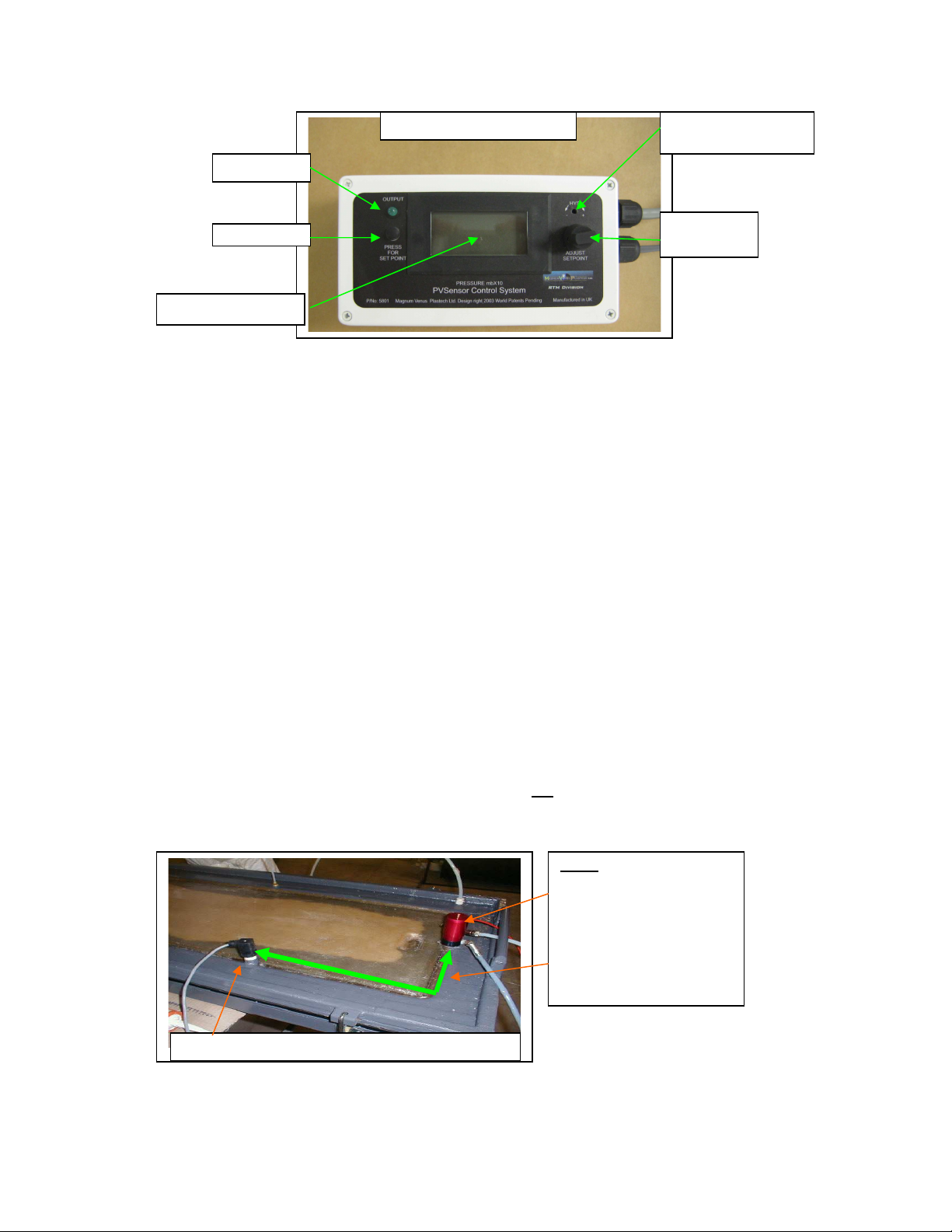
Green LED
Electronic Module Controls
Hysterisis Adjustment
– use Trimmer tool
Set-point
adjustment
LCD Display x 10mb
OPERATING THE PVSENSOR:
The resin pressure within the mould will be continuously monitored and once the set-point has
been reached a green LED will illuminate on the left hand side of the unit. This also provides a
signal to the Machine Control solenoid valve mounted within the machine.
This signal will reduce the flow of resin to the mould by slowing the machine, or stopping it all
together, so that the mould’s internal pressure does not exceed the set-point. Once the pressure
drops back the machine will automatically speed up, or start again.
Once the set-point has been reached and the solenoid energized to stop the machine (LED on),
the pressure must fall by a given amount (Hysterisis) before the unit restarts the machine. This
prevents the system from continuously starting and stopping the machine as the mould pressure
moves around the set-point (hunting). The Hysterisis is factory set and should not be adjusted
under normal circumstances.
POSITIONING AND FITTING THE SENSOR IN THE MOULD:
In LRTM moulds, the Sensor should be positioned in the resin feed channel using a mould insert
that is positioned between 300mm and 600mm from the resin input point.
For infusion applications this should be between 100mm and 200mm. If the PVS unit is to be
used solely to sense the mould pressure and not to control the machine, then the Sensor can be
sited anywhere in the mould using the Film Infusion Extension option # 5885.
It is important that the Sensor’s mould insert is installed in a vertical, or near to vertical position on
the mould’s upper (back) tool. NOTE: The Sensor is not designed to work if it is installed off
vertical by more than 30º and must not be installed, or used, inverted.
NOTE:
Injection Autosprue positioned
in the peripheral resin feed
channel.
The PVSensor positioned no
more than 600mm away from
the injection point.
PVSensor mounted vertically on upper (back) LRTM tool.
PVSensor Instruction Manual. Issue-08 25/06/2008 Page 3 of 8
Page 4

With the now standard Universal Insert laminated into the rear face of the LRTM tool, screw the
PVSensor
Complete System
# 5801
–
Parts supplied.
PVSensor clockwise into the Universal Mould insert Adapter supplied in the kit. It is important that
the PVS is screwed tightly down on the adapter so that it seals cleanly on the O ring; therefore
ensure that the top surface of the adapter is clean and smooth. - A little silicon grease smeared
onto this surface and the Sensor’s PTFE threads will help to achieve a good vacuum seal. DO
NOT OVERTIGHTEN as the PTFE Threads could become stripped.
Push the adapter firmly into the Universal mould insert and use the spring clip to retain the
adapter in the mould insert. (If desired, the old style PVS Insert # 1772 can still be used in place
of the Universal insert and adapter.)
Connect the four way PVSensor socket to the Sensor’s four pin, top plug and secure firmly in
position using the central retaining screw.
If the Sensor is not required to be used in the mould, then the Dummy Plug supplied can be used
to blank off the PVS adapter, and the Sensor can be moved to another mould.
NOTE: - For a long Sensor service life:
•
•
•
DO NOT
DO NOT
DO NOT
- Operate in an inverted position, or at an angle greater than 30º off vertical.
- Push any implement / tool into the Sensor’s PTFE cone.
- Allow release agents to flood the Sensor cone. NOTE: It may be necessary to protect
the open end of the Sensor during mould preparation and release coat application.
•
DO NOT
- Operate on automatic machine control without first confirming the safe set-point
pressure. (Simply check the set-point by pressing the left hand button on the unit and adjust
accordingly).
•
DO NOT
- Change the set-point when the Green LED is illuminated, as it will NOT provide an
accurate setting, therefore only change this setting when the Green LED is OFF
•
ALWAYS - E
nsure that the Sensor socket is firmly screwed to the Sensor during production use.
1 x Electronic Module # 5798
1 x Trim Tool # 3139
1 x Power Supply Unit # 5799
1 x PVSensor with O Ring # 5797
1 x PVS Dummy Plug with O Ring # 5785
1 x Machine Control – Solenoid Assembly # 5789
1 x Solenoid valve # 1160
1 x Silencer # 0882
1 x Coil # 1158
1 x Solenoid Socket # 5809
FITTINGS FOR RETROFIT TO PATRIOT SSB & MEGAJECT SSB
1 x 6mm Pushfit Tee # 0637
1 x 6mm Pushfit 1/8” Stud # 0620
300mm x Clear 6mm Nylon Pipe # 0208
1 x M4 x 20 Button Head Screws # 0309
FITTINGS FOR RETROFIT TO MEGAJECT MK4 & MK5
1 x 4mm Pushfit Tee # 0636
1 x 4mm Pushfit 1/8” Stud # 0619
300mm x Red 4mm Nylon Pipe # 0207
2 x M4 x 8 Button Head Screws # 0301
1 x Mounting Bracket # 6250
4 x M5 x 16 Button Head Screws # 1694
2 x M5 Nuts # 0320
2 x Nylon Spacers # 4336
1 x Universal mould Insert & Spring Clip # 6316 ( Insert # 6300) ( Spring Clip # 5834 )
1 x Universal Insert Adapter with 2 x o rings # 6317 ( O ring # 3265 ) ( Adapter # 6301)
PVSensor Instruction Manual. Issue-08 25/06/2008 Page 4 of 8
Page 5

APPENDIX A.1 - Retro-fit to Megaject MkIV and MkV machines.
other o
ption
s
.
Connecting the PVS to the
Electrical connection
Factory cut hole.
IF NOT drill 19mm hole
for Solenoid plug
Rear view of cabinet.
Internal view of PVSensor plug
MPG Regulator
Machine Control solenoid
assembly #5789
Tee in to 4mm red nylon
pipe between MPG and
MPG Regulator
Fix the Solenoid Valve through the 4.5mm hole at this point.
The exact position is NOT critical.
Megaject MkIV & MkV
PVSensor Plug inside the cabinet with
grey feed wire leading to the Solenoid
valve.
Note – The other 2 wires shown refer to
Power feed wires
to the solenoid
socket
Earth wire
1. Ensure machine is isolated from air and electrical supply before carrying out any modification or
maintenance.
2. Connect the Feed Wires (leading from the PVS plug mounted on the chassis), to the Solenoid Socket as
shown and making sure that the gasket is in place, replace the socket cover using the central retaining
screw.
3. Screw the Machine Control solenoid assembly on to the base of the yellow cabinet as per photo, using the
M4 x 12 button head screws provided.
4. Using the 4mm red nylon pipe, 4mm Tee and the 4mm stud provided, cut the 4mm red pipe leading from the
MPG block to the MPG regulator as per the photo. Insert the Tee and connect to the solenoid assembly
using the 4mm stud fitting.
5. Connect the Mounting Bracket on to the rear of the cabinet using the 2 qty M5 x 16 button head screws and
nuts provided.
6. Screw the PVS Electronic Module on to the top of the mounting bracket and connect the Module socket to
the machine mounted plug.
7. The PVSensor is now ready to set and connect to the mould.
PVSensor Instruction Manual. Issue-08 25/06/2008 Page 5 of 8
Page 6

APPENDIX A.2 - Retro-fit to Patriot SSB machines.
Connecting the PVS to the
Electrica
l connection
Soleniod Socket
and Feed Wire
2 x M5 Threaded
Mounting Inserts
Reset
Button
Sensor Plug
Machine Control
Solenoid Assembly
Tee into
6mm MPG
line
Patriot SSB
Power feed wires
to the solenoid
socket
Earth wire
1. Connect the Feed Wires (leading from the PVS plug mounted on the chassis), to the Solenoid Socket as
shown, and making sure that the gasket is in place replace the socket cover using the central retaining
screw.
2. Screw the Machine Control solenoid assembly on to the underside of the Reset Button mounted on the side
of the chassis as per photo, using the M4 x 20 button head screw provided.
3. Using the 6mm clear nylon pipe, 6mm Tee and the 6mm stud provided, cut the 6mm pipe leading from the
MPG block to the MPG regulator as per the photo, insert the Tee and connect to the solenoid assembly
using the 6mm stud fitting.
4. Connect the Mounting Bracket on to the rear of the chassis, - making sure that the 2 x spacers are
positioned in between, and fix to the chassis using the 2 qty M5 x 16 button head screws provided.
5. Screw the PVS Electronic Module on to the top of the mounting bracket and connect the Module socket to
the machine mounted plug.
6. The PVSensor is now ready to set and connect to the mould.
APPENDIX A.3 - Retro-fit to Megaject SSB machines.
1. Follow the retro-fit instructions described for the Patriot SSB. You may find that the PVSensor plug was not
factory fitted on earlier machines, or the hole drilled. If this is the case then a PVSensor Plug # 5788 suitable
for a Megaject SSB will need to be ordered from your local Magnum Venus Plastech distributor to complete
the installation, and ask for further instructions if required.
PVSensor Instruction Manual. Issue-08 25/06/2008 Page 6 of 8
Page 7

APPENDIX B
SENSOR REPAIR / CLEANING
The PVSensor measures pressures between 0 and 2000mb absolute. It is designed to work upright
and NOT inverted. This is in order that resin does not enter the small 1mm diameter hole leading to the
sensitive electronic chip placed within the Sensor’s top body.
Operated correctly in this upright position, no resin should accumulate within the cone entrance,
however when cleaning, releasing or polishing the mould, the Sensor is left in the mould in the inverted
position. - In these circumstances we recommend that the upturned cone is covered with a small foam
plug, such as PE foam or anything which protects the 1mm hole against ingress of dirt, cleaning fluid or
new release agent.
If it is found that the cone becomes contaminated, or partially blocked with resin or build up of debris
and ceases to sense the pressures we recommend the following cleaning process.
See attached diagram of cross section of Sensor
1.
Obtain a 1mm drill.
2.
Mark a drilling depth of 37mm on the drill bit, measured from the tip.
3.
Hold the drill between thumb and index finger and start to rotate the drill clockwise.
NOTE
: It is important not to simply push the drill bit into the 1mm hole at the top of the Sensor
without a drilling action, as any debris could be pushed forward damaging the Sensor’s
sensitive diaphragm.
4.
After drilling in a couple of millimetres remove the drill and tap out the debris. Continue this
action in small drilling depths and continue to tap out debris often until it is possible to read
pressure changes on the digital meter by blowing into the Sensor’s open cone end.
5.
NEVER drill deeper than 37mm.
6.
Damage to the PVSensor electronics could cause permanent damage to the PVSensor
system.
PVSensor Instruction Manual. Issue-08 25/06/2008 Page 7 of 8
Page 8

APPENDIX C
Sensor Specification Sheet
-
PARAMETER
Pressure range
Maximum overpressure
Sensitivity
Full scale span
Operating temperature
Linearity, Hysteresis Error
Type/Model; PV Sensor 0 -2bar ABSOLUTE
TYPICAL MEASUREMENT
2-30
90.0
3
90
-25 to +85
+/- 0.25% typ, +/-0.5% max. Span
UNIT
Psi(abs)
psi
m V/psi
M V
Deg C
PVSensor Instruction Manual. Issue-08 25/06/2008 Page 8 of 8
 Loading...