

Page 1

Patriot SSB Auto
Commissioning and instruction and maintenance manual
Issue 05
CONTENTS
Section Description Page
1.0 Machine Overview 2
1.1 Health & Safety General Overview 3
2.0 Instrumentation and Control Familiarisation 4-7
3.0 Priming SSB Fluid Sections 7-9
4.0 Machine Operation 9-11
5.0 Shut down 11
6.0 Routine Maintenance 11
7.0 Maintenance 12
8.0 Patriot Resin Pump 16
9.0 Catalyst Pump, CAV,OP valve and ratio system 22
10.0 Injection Head & Mixer Assembly 32
11.0 Solvent Pump 33
11.2 Solvent automatic head valve 34
12.0 RGA Resin Gel Alarm 36
13.0 SSB Auto Machine Doctor 38
14.0 Additional Machine Connections 41
15.0 Machine Air Circuit 42
Revision history 43
Patriot SSB Auto Instructions Issue 05 30/06//08
Page 1 of 43
Page 2
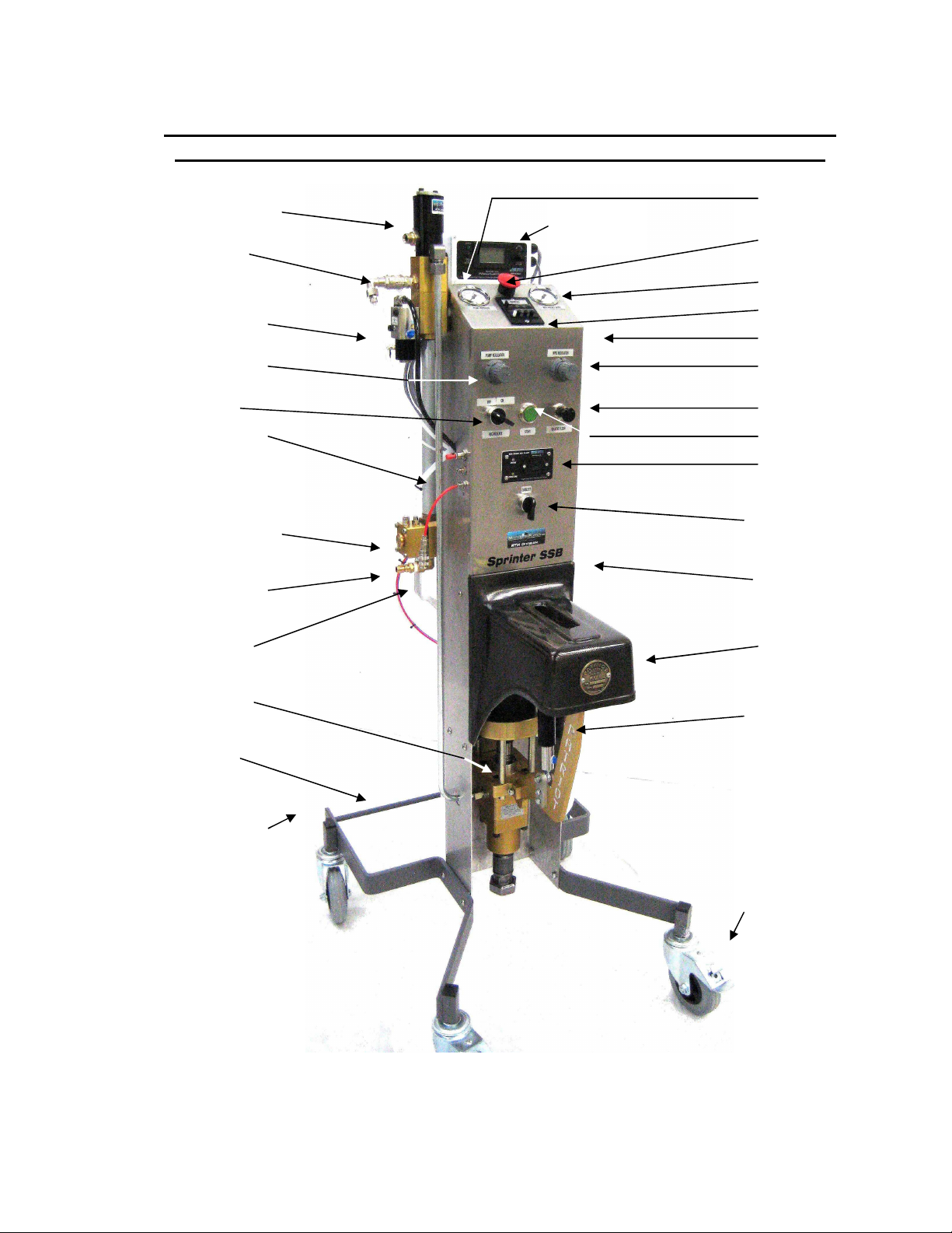
1.0 To enable understanding of machine controls please read the
following descriptions referenced to the general machine view
Resin automatic valve
Solvent automatic
valve
Catalyst automatic
valve
Pump speed regulator
Pump Start/Stop
recirculation
Static Mixer
Mould Pressure
injection hose pressure
Guard
Mixer outlet point
Catalyst Bottle 5L
Mount
Patriot Resin Pump
Solvent tank 20L
Mount
Optional Drum Trolley
fixing points
Optional PV
Sensor
system
Pump Speed air
pressure
Emergency stop/
Power ON/OFF
Mix resin pressure
Counter
Reset (Side mounted)
Mix Resin Pressure
Regulator
Solvent/Air Flush
Pump Start /Stop
Resin Gel Alarm (RGA)
MotoCat Ratio Control
Internal Lever enables
unlock of fluid section
for easy maintenance
Ratio arm Cover
Catalyst pump
Lockable Castor
wheels
Patriot SSB Auto Instructions Issue 05 30/06//08
Page 2 of 43
Page 3

1.1 Health & Safety - General over view of important health and safety
issues relating to this machine
The following instruction manual contains a number of references to controls and
procedures that will ensure safe operation of the machinery. The machines are designed
to process substances that are hazardous to health and therefore it is vital that any
materials that are introduced to the machinery have valid MSDS (material safety data
sheets) in place and that machine operators and maintenance staff are fully informed and
trained in the use of the materials and of the potential hazards.
Users are also advised to ensure that these operator instructions are correctly and
adequately made available to machine operators and maintenance staff.
Machine Guard
The Machine guard, which is supplied with this machine, must be correctly fitted at all
times during operation. Also during servicing, maintenance staff must ensure due care is
taken if it is found necessary to conduct any operational tests whilst the machine guard is
removed.
Residual Pressure
Due care should be exercised by maintenance staff to protect against any residual
pressures that may be present in the machine as discussed in the maintenance sections
Organic Peroxides
Particular note should be taken that materials utilised for the various fluid parts of the
machine are specifically selected and designed for use with Organic Peroxides and resins
The nature of organic peroxide catalysts can be reactive with certain metals and plastics.
It is therefore imperative that when renewing parts during maintenance, only genuine
MVP Ltd component parts and spare parts be fitted to the machine.
Leaks & Seals
Any leaks that become evident either compressed air or fluid from machine piping or
fittings must be investigated and corrected as soon as they become evident. Any fluid
leaks or spillages of resin, catalyst or solvent must be immediately cleaned from machine
parts or surrounding area. Cleaning materials used must be safely disposed of in
accordance with recommendations as described on the appropriate MSDS
Safety Notices
All safety use recommendation and warning labels displayed upon the machine cover and
chassis must be maintained clean and visible to the operator.
Cleaning external surfaces
Do not use solvent based cleaners on the counter or the Resin Gel Alarm (RGA) system.
All metal parts including the entire Stainless steel chassis and facia may be cleaned with
solvent cleaners.
Patriot SSB Auto Instructions Issue 05 30/06//08
Page 3 of 43
Page 4
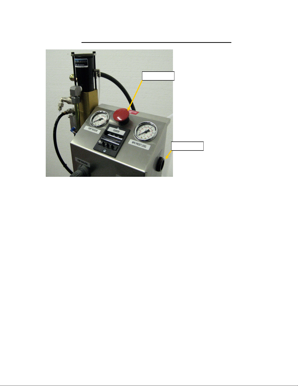
2.0 Instrumentation and control familiarisation
To switch Air supply
ON to machine.
E Stop Button
Reset Button
1. Release E
stop - Turn
counter
clockwise to
allow spring
up action
2. Press Blue
reset button
on side
Patriot SSB Auto Instructions Issue 05 30/06//08
Page 4 of 43
Page 5
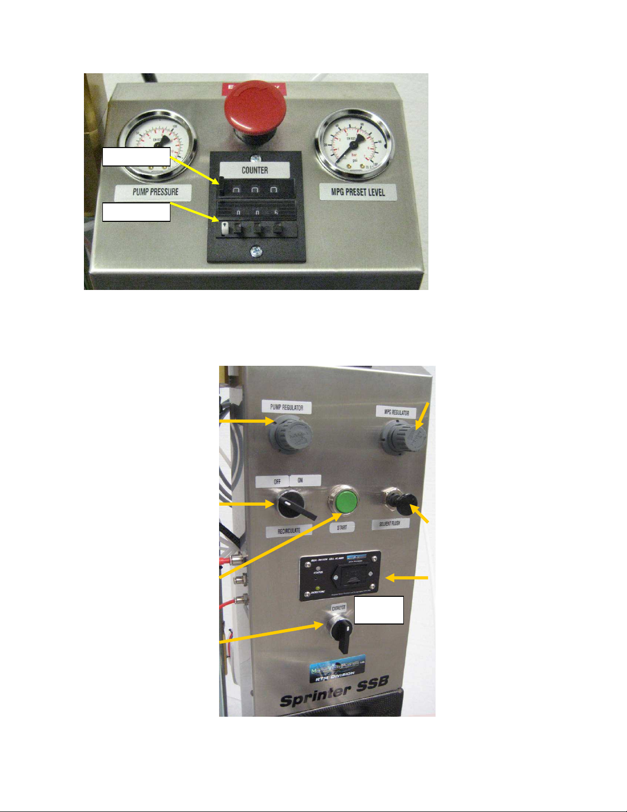
To set resin outlet line
install 9 vdc
→
+
ess
Counter reset
Count set
Note the PDC Counter can
only be adjusted when PDC
white button is continuously
pressed whilst pressing each
counter button to select
predetermined count number.
Note. If counter is set to zero
then it is NOT possible to pr
green start
Adjust air pressure
to pump motor to at
least 1 bar (15 psi)
To recirculate the
operate this control
to ON ( turn
clockwise ¼ turn)
To inject Press this
button IN
To adjust Catalyst
ratio turn to right to
increase ratio. Turn
to left to decrease
ratio
pressure limit, adjust
to at least 0.5 bar
(7 psi)
To flush head, Pull
OUT for at least 30
seconds.
Resin Gel Alarm. To
activate –
battery. See
Patriot SSB Auto Instructions Issue 05 30/06//08
Page 5 of 43
Page 6
during recirculation. It should be adjusted
downwards) during pump movement.
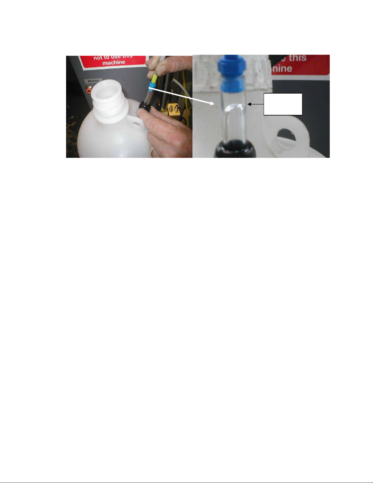
Catalyst
flow
The Catalyst Bottle mounted at the rear
of the machine is fitted with a glass tube
to allow observation of catalyst flow
to remain visible by tightening in position
Above is a typical view of the catalyst
flowing down the glass tube during
re-circulation. This flow should be
seen for each stroke (upwards or
Before proceeding to connect air supply to the machine ensure for safety reasons the
following steps are taken. Refer also to image files in Last section of this manual
• Emergency Stop/ ON/OFF button is pushed down and locked - Machine OFF.
• Solvent/Air flush switch is off (Pushed in)
• Pump Start/Stop recirculation Control is switched to OFF as marked (90º turn)
• PDC counter is set to zero 0000 counts and reset is pressed once firmly
• Catalyst Ratio arm guard is screwed into position.
2.1 Connect shop air supply to machine located at rear top of machine chassis (8mm
Push fit connector) Yellow 8mm pipe supplied
2.2 Switch on air by partially rotating anticlockwise RED Emergency Stop/ON/OFF button.
This will enable it to turn the air ON by spring UP action.
2.3 Press blue pushbutton marked “RESET”
2.4 Check machine pump operation by first clockwise increasing the Pump speed
regulator control to preset to 2 bar shown on Pump speed Pressure gauge.
Patriot SSB Auto Instructions Issue 05 30/06//08
Page 6 of 43
Page 7

2.5 Check Mix resin pressure regulator is preset at 1 bar shown on Mix resin pressure
gauge by clockwise increasing Mix resin regulator control.
2.6 Rotate to recirculation switch Pump control clockwise (90º)
2.7 The pump will now operate.
2.8. Turn Pump recirculation switch counter clockwise to OFF position
3.0 Priming SSB fluid sections. Catalyst, Resin, Solvent and pump
Lubrication.
NOTE - For safety reasons it is essential when carrying out any manual activity on the
lower guarded machine pump section that the machine is switched OFF.
3.1 Switch Machine OFF and for security isolate air by depressing E stop red button which
will lock down in OFF position
3.2 Fill Solvent cleaning tank with at least 5 litres of Acetone (see caution note below)
Maximum 20 litres. Use smaller white filler cap opening to do this. Replace cap (Do not fill
solvent tank through the large RED cap.)
Caution Note- DO NOT FILL the cleaning tank with solvent when the machine is fitted
with the SP3-NSH non solvent water based cleaner system tank. Use only water based
cleaner in these circumstances. E.g. RST-5 and HtwoO proprietary liquid cleaning
systems
The SP3 NSH tank is marked as such and is distinguished by external electrical heater
attached.
3.3 To enable access to fill the Catalyst bottle, first the black plastic catalyst feed pipe
bottle top union must be loosened to release the grip on the catalyst feed pipe. With this
done, unscrew the white bottle cap and fill bottle with the appropriate catalyst for
Polyester resin to be used. Replace cap and finger tighten the catalyst feed pipe once the
filter end is immersed and is touching the bottom of the catalyst bottle.
3.4 Place resin pickup pipe into suitable drum of pre accelerated polyester resin. Secure
pipe so that as resin container becomes empty (Lighter) the resin feed pipe does not pull
the container over causing a spillage. Also place resin recirculation pipe end securely
into resin container.
3.6 Set Catalyst ratio to Maximum Ratio by switching the MotoCat control to move the
Catalyst pump to the rear max. ratio. Note the motor will automatically stop when this
point has been reached.
Patriot SSB Auto Instructions Issue 05 30/06//08
Page 7 of 43
Page 8

3.7 Operate recirculation to ON position and observe Catalyst and Resin pipes prime with
their materials. Continue until recirculation both resin and catalyst recirculation pipes
indicate flow back into the resin tank and the Catalyst bottle to ensure full priming of all
fluid sections.
NOTE.
If the catalyst does not prime easily it is possible to loosen the catalyst pipe union at the
head catalyst inlet. (See Catalyst Auto Valve drawing 22422-8 pipe union part number
0153). By loosening this union the down stream air can easily escape during initial priming
of the pump. Once the catalyst fluid has reached the pump, stop priming and re tighten
this union 0153 before continuing thus preventing Catalyst spillage
This initial priming method is only used for initial priming of a new machine from empty. It
is NOT necessary to use this method again once the machine has been in use.
3.8. Stop pump and prepare to prime head block and mixer for the first time.
3.9 IMPORTANT. Attach the 1 metre priming Pipe securely with quick release connection
to Mixer outlet point. Secure the other end in a waste container. Alternatively the Turbo
Autosprue (TAS) may be connected but so that it does not open during this initial priming
exercise simply do not connect the 4 mm TAS red signal line. However do secure the
clear 10mm drain pipe safely to a waste container.
3.10. Set pre determining counter to at least 10 counts and press counter reset button
3.11 Press inject green button. The pump will start and then stop after the predetermined
volume of resin mix has been dispensed into the container.
3.12 The RGA Resin Gel Alarm will sound within n30 seconds (see separate section on
RGA at the end of this section 3.)
3.13 Operate (Pull) solvent Air flush control. Allow machine head and mixer to flush clean
and dry out with air flow for about 35 seconds. Return solvent /air flush control to off
position. (PUSH IN)
b/ The machine design has build in safety preventing inadvertent operation of the flush if
the operator attempts to flush during injection. The flush control will only be active when
the machine is NOT injecting
The machine is now fully primed and ready for first mix and gel test before production
operation.
3.14 Resin Mix gel time test
It is important that the mixed resin reactivity (gel time) needs to be checked before
injecting a mould. It is wise therefore to make a test mixture from the machine mix head in
Patriot SSB Auto Instructions Issue 05 30/06//08
Page 8 of 43
Page 9

order to determine this gel time exactly at the ambient temperature and for selected
catalyst ratio.
To carry out a mix and gel test set the desired catalyst ratio and then simply follow the
same procedure from stages 3.9 to 3.13 above but direct the mixed resin safely into a gel
test container. Once the resin mix sample has been dispensed and the machine has
stopped, place the resin outlet pipe securely into the waste container before flushing the
head and pipe.
3.15 General notes on gel time.
a/ It is wise to set and confirm gel times at least 30% longer than mould fill time
b/ Remember that UP resin will gel twice as fast for a 10°C increase in resin temperature.
c/ Be aware that cool resin is significantly more viscous than when at normal room
temperature. In these circumstances allow more time to fill the mould and thus more time
for gel time is needed to ensure mould fill without pre gel condition.
d/ As a guide, MVP’s experience has shown a general UP low viscosity resin suitable for
injection has given the following general specifications on gel time
Using 6% strength Cobalt Naphthalate ( 6% CN) as the primary accelerator and AAP
catalyst
0.1% CN = 1 hour gel time with 1% AAP catalyst
0.2% CN = 20-30 minutes gel time at 1 % AAP catalyst
0.3% CN = 15-25 minutes gel time at 1% AAP catalyst
A typical 20 minute gel time would be formulated with 0.2% CN with 2 % AAP catalyst
ratio setting.
These figures are given as a guide and must be checked for your chosen UP resin
system. Some resins are supplied already accelerated however users often add more CN
accelerator to speed u the resin gel time if found too slow.
4.0 Machine Operation
4.1 RTM or Light RTM operation
4.2 Adjust Catalyst ratio to required setting
4.3 Attach Mould to Mixer output point using 10 mm nylon pipe or via Autosprue® or
Turbo Autosprue brass quick connect. IMPORTANT –Ensure this is locked into position.
Notes a/ Additional lengths of 10mm pipe are available from MVP Ltd.
b/ The TAS 4mm red signal pipe is connected to the SSB chassis connection on
the left hand side 4mm central connector marked Autosprue signal.
Note- do not mistakenly connect to the lower 4 mm chassis connector as this
is a remote start optional connection and if connected to the Turbo AS it will
actually start the machine.
Patriot SSB Auto Instructions Issue 05 30/06//08
Page 9 of 43
Page 10

These are marked and located on the LH side of the chassis next to the Mixer
output point. see diagram illustration at end of this manual referring to additional
connections.
Note – The 6 mm Autosprue connection at this location is no longer required
for the latest Turbo Autosprue (TAS) and should remain plugged. However
this point can be utilised by the user as an air gun pressure connection point
or to the Vacuminder.
4.4. Injection operation start and stop
Injection is carried out by setting the Pre determining counter (PDC) lower number set to
the expected volume of resin required. Each digit count represents a volume of resin
approximately equal to 38 cc. To determine exactly the volume collect 10 strokes of resin
accurately from the recirculation resin hose end and observe how much it weighs or
volume for the 10 strokes. If 10 strokes measure 380 ml (0.38 Litres) then each stroke
(numeric count on the counter will give a volume of 38cc. .
Be aware that a count of ten should only be made once the mixed resin has filled the
mixer and pipe
Once the predetermined counter has been set and the PDC counter top LH reset button
has been pressed firmly and the outlet pipes are connected to the mould simply press in
the green start injection button. The machine will now open both the head resin valve and
catalyst valve and internally provide the machine control with a confirmation signal to
start. The machine will dispense/inject the PDC volume of catalysed resin. Speed of
injection can be adjusted by the pump speed regulator. Upon reaching the PDC set count
the machine will stop automatically and the head valves and Autosprue will close safely.
4.5. Once the machines stops, the Resin gel alarm (RGA) will sound after 30 seconds (if
flush is not operated) to warn that the head needs to be flushed. Operate the Flush pull
switch for a minimum of 30 seconds. As soon as this switch is activated to flush the alarm
(if sounding) will cease but the red flashing warning will only extinguish after 30 seconds
confirming that sufficient air drying time has elapsed.
Note if the flush control is pushed in, to stop flushing sooner than 30 seconds the RGA
alarm will sound once more warning that not sufficient time has been allowed for the
recommended air dry out time. If this happens simply operate the flush pull switch once
again and only push back in to stop after 30 seconds has elapsed which is confirmed by
the RGA red flashing light ceasing and the RGA going back into sleep mode (No lights
and no alarm.)
Note if a count of resin is set greater than required it is necessary to stop the machine
manually. To stop the machine under this circumstance simply hit the E stop followed by
unlocking the E stop and pressing the blue reset button. .For security reasons the
machine systems will not allow flush if the green start button is depressed ON. Only the
Patriot SSB Auto Instructions Issue 05 30/06//08
Page 10 of 43
Page 11

count reaching the pre determined count or hitting E Stop and resetting the machine to
ON will allow flush to take place.
Finally if a count on the PDC was set too little and more resin is required to fill the mould
simply press the PDC rest button followed by pressing the green start button once again.
As this selects the original count set, the machine will now continue to pump until the full
reset count is achieved. Stop the machine as described above in these circumstances
and record the number of extra counts the mould needed. This will allow a more accurate
count to be set for the next injection cycle on the same mould.
5.0 Shut down
5.1 Operate the pump to the down stroke limit by using of the recirculation switch. This
ensures that the resin pump piston shaft remains unexposed to air during shutdown and
thus lengthens the life of the shaft seal.
5.2 Turn off machine air supply by pushing the emergency stop button to OFF locked
position.
6.0 Routine Maintenance
General.
Ensure working parts of machine are kept clean. Also ensure all controls and indicators
remain clean. The gauges are glass faced and can be cleaned with solvent however all
other plastic controls should be cleaned with non solvent based cleaners. Remove all
spillages from machine. Immediately correct any air leaks or seepage of any fluid from
machine.
6.1 Resin pump. During normal use the resin pump lubrication cup needs to be topped up
with pump lube. This should be checked at least once a week during normal daily
production use. See separate sheet on internal part maintenance in section 9.0
6.2 Catalyst pump and feed and recirculation pipes. The catalyst pump needs no regular
maintenance however any seepage producing catalyst spillage from the machine from
catalyst pump top seal indicates catalyst pump top seal replacement. See separate sheet
on internal part maintenance in section 10.0.
Please note seepage of catalyst NOT producing leakage onto the workshop floor
from this point on the catalyst pump is acceptable.
Visually check security and condition of catalyst feed pipe from Catalyst bottle and smaller
recirculation pipe and all associated fittings. If any show signs of wear, seepage or
damage, replace with new parts immediately. Ensure Catalyst feed pipe is routed from
catalyst bottle to pump lower fitting around the right hand outside of the machine chassis
Patriot SSB Auto Instructions Issue 05 30/06//08
Page 11 of 43
Page 12

The catalyst inlet filter located within the catalyst bottle should be removed and cleaned in
solvent and water at least every 4 months.
The Catalyst bottle internals must remain clean. If catalyst appears to be discoloured or
any form of sediment is observed within the catalyst bottle remove and clean as
necessary and dry out before replacing with fresh catalyst and placing back into service.
Use only water through the catalyst system if cleaning is necessary. Do not use or pump
solvent based cleaners in the catalyst fluid section
6.3 Solvent Pump system. The Solvent tank requires no routine maintenance however if
dirt particles as sediment accumulate within solvent tank base remove and clean and refill
with fresh solvent.
The remaining solvent system should only be routinely maintained by weekly checks to
locate any leaks or damaged pipes which should be repaired immediately.
See separate sheet on internal part maintenance in section 12.0
6.4 Mixing head assembly. The Resin mix pressure sensor (Mould Pressure Guard MPG) has an internal diaphragm which should be renewed periodically. A renewal rate
after every 10,000 Kg mix usage is recommended. See sections 11.0 and 11.1
7.0 Maintenance
Important Safety Note All maintenance work on the machine must be carried out with the
air supply to the machine disconnected and due caution must be observed when opening
all fluid and pneumatic connections by using personal protection against possible
internal residue pressures.
The following sections describe seal and internal fluid section maintenance procedures
accompanied by assembly and parts drawings.
Maintenance feature for ease of access.
It is now possible to remove the entire Patriot fluid section once the air pipes and fluid
pipes have been disconnected. There are NO bolts holding this section in the machine.
Instead the unit is locked into position with an over centre lever lock.
It is a simple and rapid procedure to remove the pump and is recommended if any main
maintenance operations are to be carried out on this section.
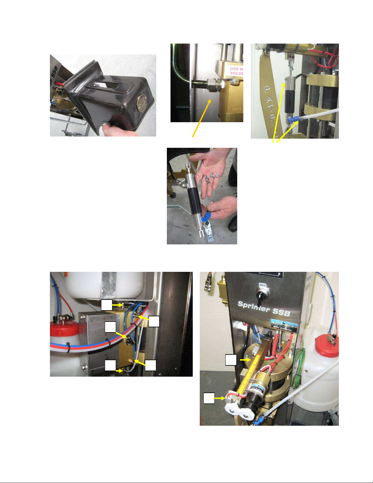
Proceed as follows.
1. Lift catalyst and resin intake wands above fluid levels and recirculate to empty both fluid
section.
2. Remove pump guard and the resin outlet and catalyst outlet pipes. Take care to mob
up slight fluid seepage from these unions as they will still have a small residue of fluid
Patriot SSB Auto Instructions Issue 05 30/06//08
Page 12 of 43
Page 13
1
2
3
4
5
1
2
Remove guard Disconnect resin outlet Disconnect Catalyst
inlet and outlet
3. Disconnect 5 pneumatic pipe connection at rear of pump air motor and 2 at front on
MotoCat .
Disconnect 5 pipes to pump air motor ↑
Disconnect 2 red MotoCat feed pipes
→
Patriot SSB Auto Instructions Issue 05 30/06//08
Page 13 of 43
Page 14

pe
ease of access.
1/ Red lever up
to unlock.
2/ The pump assembly can now be eased from
the machine. In the picture the catalyst pump has
already been unclipped. Note the resin intake pi
can remain connected to prevent residue fluid
spillage
The entire fluid
section may now
be bench
mounted for
Patriot SSB Auto Instructions Issue 05 30/06//08
Page 14 of 43
Page 15

The resin pump can be disengaged from the air motor by releasing the circlip (APP-9102)
and lifting the shell retainer (PAT-PA-9109) upwards. This allows removal of the two half
shell connectors (APP-9096). Remove the 4x bolts (F-HB-06C-24-GR8). The resin intake
pipe, if removed, should be disconnected at swivel fitting (4233)
The Patriot resin pump may now be removed for service
Patriot SSB Auto Instructions Issue 05 30/06//08
Page 15 of 43
Page 16

8.0 Patriot Resin Pump
Patriot SSB Auto Instructions Issue 05 30/06//08
Page 16 of 43
Page 17

General Note When rebuilding pump assemblies use
and component mating surfaces
Red
Grease (6706-2-1 1 oz) on seals
Seal replacement. – Piston shaft seals (PAT-LS -1016)
1. To replace piston shaft seals (PAT-LS -1016) first remove four bolts (CS-06C-32) from
lower inlet body (PAT-LS-1002)
2. Secure the upper outlet body (PAT-LS-1001) and push the piston shaft (PAT-LS-1008)
downwards. This will force the lower inlet body and upper body apart. Put the lower body
aside complete with the piston shaft assembly.
Patriot SSB Auto Instructions Issue 05 30/06//08
Page 17 of 43
Page 18

3. The one piston rod seal can be removed after first unscrewing the Packing nut (PATLS-1006).
4. Before replacing the new seals ensure that the entire housing is clean. Lightly grease
the seal housing and packing nut thread section. Check also the rod bushing (PAT-LS-
1005) for wear and damage and replace as necessary.
5. The seals must be pushed into the housing evenly. A simple way by which the new
seals can be installed is by first placing one seal (Lip down) into the outlet body so that it
rests horizontal. Now the packing nut can be screwed down upon the seal by hand which
will progressively push the first seal down with an even parallel force. Once screwed by
hand as far as possible, unscrew the packing nut and repeat this exercise with the second
seal (lip down).
6. Finally back off and retighten the packing nut so that it just makes contact with the
seals which are now firmly in their housing bottom position.
Seal replacement. – Piston seal (PAT-LS-1014)
7. Withdraw the piston assembly from the lower intake body and place aside taking care
not to drop or damage the high tolerance surfaces of the rod or larger piston diameter.
8. The piston seal (PAT-LS-1014) can be removed after lifting out the bush (PAT-LS -
1013).
9. Ensure the new seal is placed inside the lower intake body with the O ring lip seal
upper most as indicated. Also note the bush must be placed on top of the seal with the
wider edge down as indicated. Fit the O ring (0-E-035) over the bush before inserting the
piston and re assembling the upper outlet body.
Inlet Valve (PAT-LS-1015) Disassembly
1. Using a pair of Pliers squeeze the Ball Stop (VLS-2420) and remove it from the Inlet Valve (PATLS-1015).
Patriot SSB Auto Instructions Issue 05 30/06//08
Page 18 of 43
Page 19

2. Remove the Foot Valve Spring (3102-16-1) and Ball (PAT-LS-1017) from the Inlet Valve.
NOTE: Use care not to drop the hard chrome balls in the Inlet and Piston Bodies as they will
be damaged. Replace all parts provided in the repair kit. Use only original MVP parts.
•
Inlet Valve Assembly
1. Properly clean Inlet Valve (PAT-LS-1015) checking the ball seat area.
2. Install a new O-Ring (O-E-3-920) on the Inlet Valve, lubricate O-Ring and threads with Red Grease
(6706-2-1 1 oz).
3. Lightly grease the Inlet Ball (PAT-LS-1017) with Red Grease and place in the Inlet Valve.
NOTE: Use care not to drop the Inlet ball as it will be damaged.
4. Install the Foot Valve Spring (3102-16-1) onto the Inlet Ball, narrow side against the Ball.
5. Place the back of the Ball Stop (3102-16-1) on top of the Foot Valve Spring and into the grove in the
Inlet Valve, using a pair of Pliers squeeze the Ball Stop (VLS-2420) and push the front into the
grove. Set it aside for now.
•
Inlet Body Assembly –
6. Properly clean Inlet Body (PAT-LS-1002), lightly lubricate the threads and seal area with Red
Grease (6706-2-1 1 oz).
7. Screw the assembled Inlet Valve Assembly into the bottom of the Inlet Body (PAT-LS-1002),
lightly tighten.
8. Mount the Inlet Body into a vice by the flats on the Inlet Valve.
NOTE: Secure the pump vertically in
the vice by the flats on the Inlet Valve
or the Inlet Body. Use care not to
damage the pump when clamping it
into a vice. Use a soft jawed vise or a
towel or rag between the vise and
pump.
•
Fluid Rod & Piston Assembly –
Patriot SSB Auto Instructions Issue 05 30/06//08
Page 19 of 43
Page 20

9. Properly clean Piston (PAT-LS-1007), Fluid Rod (PAT-LS-1008) and Piston Valve (PAT-LS-1009),
check ball seat area of the Piston Valve for damage or debris.
10. Install a new O-Ring (O-E-3-916) on the Piston Valve, lubricate O-Ring and threads with Red
Grease (6706-2-1 1 oz).
11. Lightly grease the Piston Ball (VLS-2427 and place in the Piston Valve.
NOTE: Use care not to drop the Piston Ball as it will be damaged.
12. Install the Spring (PAT-LS-1010) onto the Piston Ball, narrow side against the Ball.
13. Place the back of the Spring Retainer (PAT-LS-1011) on top of the Spring and into the grove in the
Piston Valve, using a pair of Pliers squeeze the Spring Retainer (PAT-LS-1011) and push the front
into the grove.
14. Screw the Piston Valve Assembly into the bottom of the Piston and tighten firmly. Check that the
Fluid Rod (PAT-LS-1008) is tightened onto the Piston (PAT-LS-1007).
•
Pump Assembly –
1. With the assembled Inlet Body mounted
in the vise slowly and firmly push the
Piston and Fluid Rod assembly all the
way down into the Inlet Body.
2. Carefully and firmly
push the assembled
Outlet Body onto the
Inlet Body until the
Fluid Rod extends
though the Packing
Nut.
Patriot SSB Auto Instructions Issue 05 30/06//08
Page 20 of 43
Page 21

3. Align the Inlet and Outlet Bodies and install the four Socket Headed Cap Screws (CS-06C-32).
Patriot SSB Auto Instructions Issue 05 30/06//08
Page 21 of 43
Page 22

9.0 Catalyst Pump - Catalyst pump parts drawing
Patriot SSB Auto Instructions Issue 05 30/06//08
Page 22 of 43
Page 23

9.1 Catalyst pump piston seal.
The Patriot SSB model is designed with a new type of internal Piston valve. This new
design has dispensed with the conventional small ball and spring metal to metal types
formally common in the industry.
In the new design the valve action is generated by the fact that the piston assembly has a
very small amount of “slop” or lost motion.
It is essential therefore that during any maintenance on the piston seal the correct
lost motion is set as detailed below and is observed before re assembly after
service of this section.
To access the pump piston seal or any other internal pump parts proceed as follows.
1 Adjust ratio to maximum
2/ Lift the filter end of the catalyst feed above the catalyst bottle fluid level, operate
recirculation to pump out catalyst from system. Continue to pump until air bubbles appear
in the return flow sight glass.
3/ Remove catalyst feed pipe from the inlet (assy. 0099) and the outlet pipe connection
(6150). The inlet fitting should only be hand tight. Take care to collect or wipe away any
residual catalyst as the fitting is opened
4/ Unclip top and bottom clevis pins to allow pump removal (4279)
5/ Unscrew by hand the lower catalyst block (PS 4282) from pump body.
6/ Unscrew outer tube (PS 0526). The pump cylinder (PS 0525) is now exposed.
Remove this by pulling and sliding off the pump shaft and piston assembly.
7/ Loosen locking nut 6256 and unscrew the piston retainer M4 screw (5692) using 2.5 AF
Allen key The piston assembly will remain upon the screw as it is removed.
8/ Remove the Piston assembly from the screw and unscrew the piston (4234) from the
retainer bush (4235). Withdraw the piston seal (1712).
9/ Replace with new seal. Observe the correct” lip up” orientation of the seal as detailed
on figure 33 below. Do not force seal onto piston (4234) unevenly. Best results are
obtained by placing seal in position (lip upper most) and hand tightening piston and bush
back together. Do ensure assembly is fully retightened. It should measure 13.5 mm
(0.524”) when tightened. Piston valve seal O ring (5684) may be renewed at this time.
Patriot SSB Auto Instructions Issue 05 30/06//08
Page 23 of 43
Page 24

Figure 33. Catalyst piston assembly lost motion setting (assy 0100)
Warning Notes.
If the piston seal assembly is not assembled as per the instructions concerning the lost
motion tolerance the following will occur.
a)
If there is no gap then the pump will seize solid on the down stroke when filled with
catalyst.
b)
If the gap is too great poor catalysation will be evident in the mix.
Important. Ensure the piston bush (4235) is screwed onto the piston the correct way up.
The four small V grooves on the bush MUST be uppermost as shown
Patriot SSB Auto Instructions Issue 05 30/06//08
Page 24 of 43
Page 25

The reassembly of the piston assembly using the piston retaining screw must only be
done when the Piston shaft is mounted back through the top block.
The screw should be set at the right position to set the desired 0.5 to 1.0 mm (0.020” to
0,040” ) lost motion gap and locked in position with locking nut 6256 however we
recommend medium thread locking solution is used to secure its correct position as an
additional security measure. (I.e. Loctite® 243)
Do not attempt to remove the top piston rod clevis (4278) from the shaft as this is
permanently thread locked together.
The remaining parts are reassembled in the reverse order
9.2 Catalyst pump Piston shaft seal
The top seal (0535) can be removed and replaced by following the above description to
remove the pump and disassemble. The piston assembly must be removed so that the
piston rod can be withdrawn and top seal housing (4236) and spacer (4237) can be
pushed forward from the top of the top block to remove and gain access to piston rod seal
(0535).
9.3 Catalyst Over pressure Valve (O/P valve)
Patriot SSB Auto Instructions Issue 05 30/06//08
Page 25 of 43
Page 26

The Catalyst Over pressure valve (OPV) is a pressure switch designed to stop the
machine pumping in the unlikely event of catalyst fluid section blockage causing high
pressure. This unit has been factory set and tested by MVP. It will trigger the machine
pump OFF for pressures higher than 24 bar (350 psi)
The OPV is mounted inside the machine covered chassis on the left hand side and
secured on a robust nylon clip.
If for any reason the user needs to install new O ring seals (0750) then only the front
Stainless steel body (1032) should be unscrewed from the pressure switch brass body.
Do not disturb the Brass body end cap setting as this will invalidate the factory pressure
setting.
9.4 Catalyst Ratio arm - MotoCat
Patriot SSB Auto Instructions Issue 05 30/06//08
Page 26 of 43
Page 27

There are no serviceable parts associated with the above assembly and no lubrication is
necessary. Periodically check for and tighten any loose screws and fittings if noted.
Patriot SSB Auto Instructions Issue 05 30/06//08
Page 27 of 43
Page 28

10.0 Injection Head and Mixer assemblies
Patriot SSB Auto Instructions Issue 05 30/06//08
Page 28 of 43
Page 29

10.1 Catalyst Auto valve assembly. – CAV
Servicing notes.
The catalyst auto valve needs little servicing as all components are suitable for both MEKP
and recommended AAP catalysts
The movement of the spool as indicated from the aluminium air cylinder end should be
between 4 and 5 mm. Any less or greater can cause Catalyst to flow incorrectly so ensure
this movement is observed to be correct by measurement using callipers after service and
before using the machine in production.
Take care not to damage or scratch the spool internal body 6369 when O ring 3316 needs
replacing.
Patriot SSB Auto Instructions Issue 05 30/06//08
Page 29 of 43
Page 30

The valve should only need servicing if air or catalyst is noted to weep from between the air
cylinder 6078 and Stainless steel body 6067. In this case the O ring 3316 should be
renewed.
If catalyst appears to weep back to the catalyst bottle during injection mode then the internal
spool O rings (6004) need replacing.
If catalyst is observed to weep from the injection nozzle during recirculation mode then the
small front O ring (6079) needs replacing. .
Injection Recirculation
Illustration of Catalyst
Auto valve cross
section showing
catalyst flow and
correct position of air
actuator for
A. injection flow
And
B. recirculation flow
Patriot SSB Auto Instructions Issue 05 30/06//08
Page 30 of 43
Page 31

10.2 Auto Resin Valve assembly - RAV
Caution Note. For safety reasons - Always ensure that the Resin Auto valve above is
locked into the head top position with the two securing lock M5 screws 4081
Patriot SSB Auto Instructions Issue 05 30/06//08
Page 31 of 43
Page 32

10.3 Head Mixer and Mould pressure Guard (MPG)
Patriot SSB Auto Instructions Issue 05 30/06//08
Page 32 of 43
Page 33

11.0 Solvent pump NEW SP3 (Jan 2003 onwards)
Note. With the introduction of the new Stainless Steel SP3 Solvent pump system on models
supplied from January 2003 it is possible to upgrade previous machine models with this unit.
It is a simpler design over the former SP2 system and has greater cleaning efficiency as
there is greater throughput of air to the pump and thus to the mixing head.
Patriot SSB Auto Instructions Issue 05 30/06//08
Page 33 of 43
Page 34

11.1 SP3 assembly
11.2 Solvent valve Assembly 58742-PLAS
. The automatic solvent head valve may be serviced. However note the important use of
thread locker solution (recommend Loctite 242 between parts 3 and 6. This needs to be
disassembled if the main solvent seal 19 needs renewing.
Patriot SSB Auto Instructions Issue 05 30/06//08
Page 34 of 43
Page 35

Patriot SSB Auto Instructions Issue 05 30/06//08
Page 35 of 43
Page 36

12.0 Resin Gel Alarm – RGA
Start – Green
Alarm
- Red
flashing
Power on
Injecting
- Yellow
Battery low
-Yellow flashing
The RGA unit is set to operate only when injection takes place. On injection start both the
green light and yellow light illuminate.
If injection is either stopped or the machine stops pumping (stalled) for more than 60 -120
seconds the Top green light will change colour to Red flashing mode and an audible alarm
will sound.
If injection is restarted then the Red light changes back to Green and the alarm warning
stops.
At the end of injection when the counter or the operator stops the injection and proceeds to
flush the machine head the Red light will continue to flash for 30 seconds (without the
audible warning) and the RGA unit will then revert to sleep mode.
If the operator switches off the flush command earlier than 30 seconds the audible warning
will start again with the red light still on demanding that a full 30 seconds of flush and head
mixer air dry out is commanded.
Low battery.
9 VDC
battery (PP3
type)
Patriot SSB Auto Instructions Issue 05 30/06//08
Page 36 of 43
Page 37

The internal 9 vdc battery is accessed by sliding out the front battery draw. Under normal
use the standard PP3 9vdc battery should last for more than two weeks. If the battery has
insufficient volts the lower yellow light will flash. If this condition is observed immediately
renew the battery.
Gel time Changes
If the gel time is to be reset to another time interval it is necessary to access the rear of the
RGA enclosure. Here will be found a small blue adjuster wheel on the box rear face. By
rotational switching clockwise the time will be increased and decreased if rotated anti
clockwise
RGA Alarm time set switch.
Use small screwdriver to
adjust. DO NOT force beyond
stops
As previously stated, the time before the alarm is activated can be selected by the user,
based on the resin system being utilised. On the SSB machine model it is necessary to open
the control fascia to access this RGA rear position. This is achieved by setting the rotary
switch, located on the rear of the RGA, to the position for the required time as specified in
the following table.
SWITCH SETTING Pump inactivity time (minutes)
0 0.25
1 0.5
2 1
3 2
4 3
5 4
6 5
7 6
8 7
9 8
A 9
B 10
Patriot SSB Auto Instructions Issue 05 30/06//08
Page 37 of 43
Page 38

C 12
D 15
E 20
F 25
13.0 SSB Auto Machine Doctor
This table provides typical fault conditions their possible causes and remedies
Fault
symptom
Machine fails to
start on
recirculation or
injection
command
2. Pump speed set too
3. MPG set too low Set MPG pressure higher
ON injection
command
( when green
button is
pressed)
5. PDC Counter not
6. Catalyst over
5. Catalyst head valve
Possible cause Remedies
1. Air supply too low Ensure air supply at least 6 bar
(90psi)
Set at least to 1 bar and above
low
4. Auto head valves
NOT reached open
inject position and thus
not providing start signal
to machine
reset correctly or set at
zero
pressure valve operated
- Either the NRV4 has a
blockage OR the head
mixer is blocked.
has not fully opened
when commanded by
injection command
Check both Resin and catalyst head
valve have moved to open position.
Observe Metal pin at pneumatic
actuator has moved out.. Approx 8
mm for Resin valve and 5 mm for
catalyst valve. If not then increase
shop air pressure or service the
valve at fault.
Press reset firmly or set at least a
count of 5
Check Catalyst Over pressure valve
is NOT leaking small air volume
from brass body end cap
If this valve has an air leak then it
has triggered the machine to stop.
Investigate why the valve has
triggered as it indicates the catalyst
has found significant blockage.
Inspect NRV8 for signs of blockage
Check both the resin auto valve and
the catalyst auto valve have opened
.The Resin valve must fully open to
signal the catalyst valve to open.
Both should indicate their
respective open positions by the
Patriot SSB Auto Instructions Issue 05 30/06//08
Page 38 of 43
Page 39

Resin valve brass pin raised above
the black valve top by at least 7
mm. (0.276”)
The catalyst auto valve (CAV)
should show the movement open by
the aluminium pin raised by at least
5 mm (0.200”) from the closed
position.
Service the valve which is showing
signs of not fully opening.
6. Resin head valve
blocked .This condition
could happen if the
machine has been left
with resin in the system
for extended times
without use.
Internally clean and if necessary
renew internal parts.
Caution NOTE. Always replace the
resin valve locking M5 screws
securely after servicing the Resin
auto valve.
Catalyst flow
appears erratic
1. Air in catalyst feed
pipe or Fluid section
Re purge catalyst system.
Contaminated catalyst also causes
bubbles in system. To remedy
empty entire catalyst system
including catalyst bottle. Wash out
with clean water. Dry, and Refill
with fresh Catalyst
2. Catalyst Gassing -Clean catalyst system of
contamination.
- Preferably use AAP catalyst
system as MEKP has a greater
tendency to produce gas bubbles
more readily than the more stable
AAP systems
Resin flow has
bubbles or
appears erratic
1. Air leaks in the resin
feed intake system.
1.Check all joints for leaks in intake
pipe work and fittings on the resin
pickup fluid section
2. Resin filter blocked Clean resin intake filter
3. Resin Filler loading
too high
Lower viscosity of resin OR lower
pump speed until even flow on up
and down pump strokes is observed
Flush does not
clean efficiently
1.Low air supply
pressure
Ensure supply pressure between 6
to 8 bar (90 – 120 psi)
or appears
weak
2.solvent valve assy
blocked or broken
Check assy 58742-PLAS internal
seat and spring
Patriot SSB Auto Instructions Issue 05 30/06//08
Page 39 of 43
Page 40

3.Mixer partially blocked Check mixer and renew if
necessary
Catalyst pump
1. Worn top seal Renew seal
top seal
leakage
beyond top of
pump
2. Catalyst pump piston
Renew seal and pump shaft.
shaft
damaged/scratched
Resin pump top
1. worn top seal Renew seal
seal leaking
beyond pump
lube zone
2. Top seal worn quickly
due to non lube renewal
Observe recommended pump lube
renewal
3.resin pump left for
extended times in UP
Observe recommended service
notes on pump parking position
position causing shaft to
become dry
4.Filled resin use A shorter service life will be
expected if highly filled resin is
used. Service life depends on filler
type and filler micron size. Use only
coated fillers with 5 micron filler
particle size
Patriot SSB Auto Instructions Issue 05 30/06//08
Page 40 of 43
Page 41

Additional SSB
Connections
Patriot SSB Auto Instructions Issue 05 30/06//08
Page 41 of 43
Page 42

Machine air circuit
Patriot SSB Auto Instructions Issue 05 30/06//08
Page 42 of 43
Page 43

Issue record – Revision history
Issue 05 dated 30/06/08 arh
– All reference to hand operated head solvent valve deleted .Also NRV2 deleted. Now using automatic air
operated solvent valve assy 58742-PLAS
Patriot SSB Auto Instructions Issue 05 30/06//08
Page 43 of 43
 Loading...