

Page 1

Megaject MKIV
Manufacturing Technology Centre,
Chilsworthy Beam,
Gunnislake,Cornwall,PL18 9AT, UK
Tel: +44(0)1822 832621 Fax: +44(0)1822 833999
e-mail: rtm@plastech.co.uk
http://www.plastech.co.uk
Instruction Manual
Revision 1_2
Machine Serial Number: KO30141
Megaject MK IV Issue 1_2 25/11/2003 Page 1 of 31
Page 2

Contents
1. Megaject MK IV Overview
Introduction
Injection Head
Machine Front Guard
Catalyst System
Solvent Tank
2. Operating Controls
3. Commissioning and Set-up Procedures
4. Filling/Refilling Solvent Tank
5. Setting Catalyst Percentage
6. Recirculating & Repriming
Recirculating
Repriming
7. Injecting & Flushing
Before Injection
Injection
Flushing
8. Optimising Output
9. Shutdown Instructions
10. Maintenance
Maintenance Schedule
Replacing Resin Pump Seals
Replacing Catalyst Pump Seals
Servicing Injection Head
Mixer Tubes
Resin & Catalyst Pipework
Catalyst Overpressure Valve
Machine Air Circuit
Solvent Pump
11. Appendices
Mould Pressure Guard
CATAL catalyst monitoring system
Resin Heaters
Revision History
Megaject MK IV Issue 1_2 25/11/2003 Page 2 of 31
Page 3
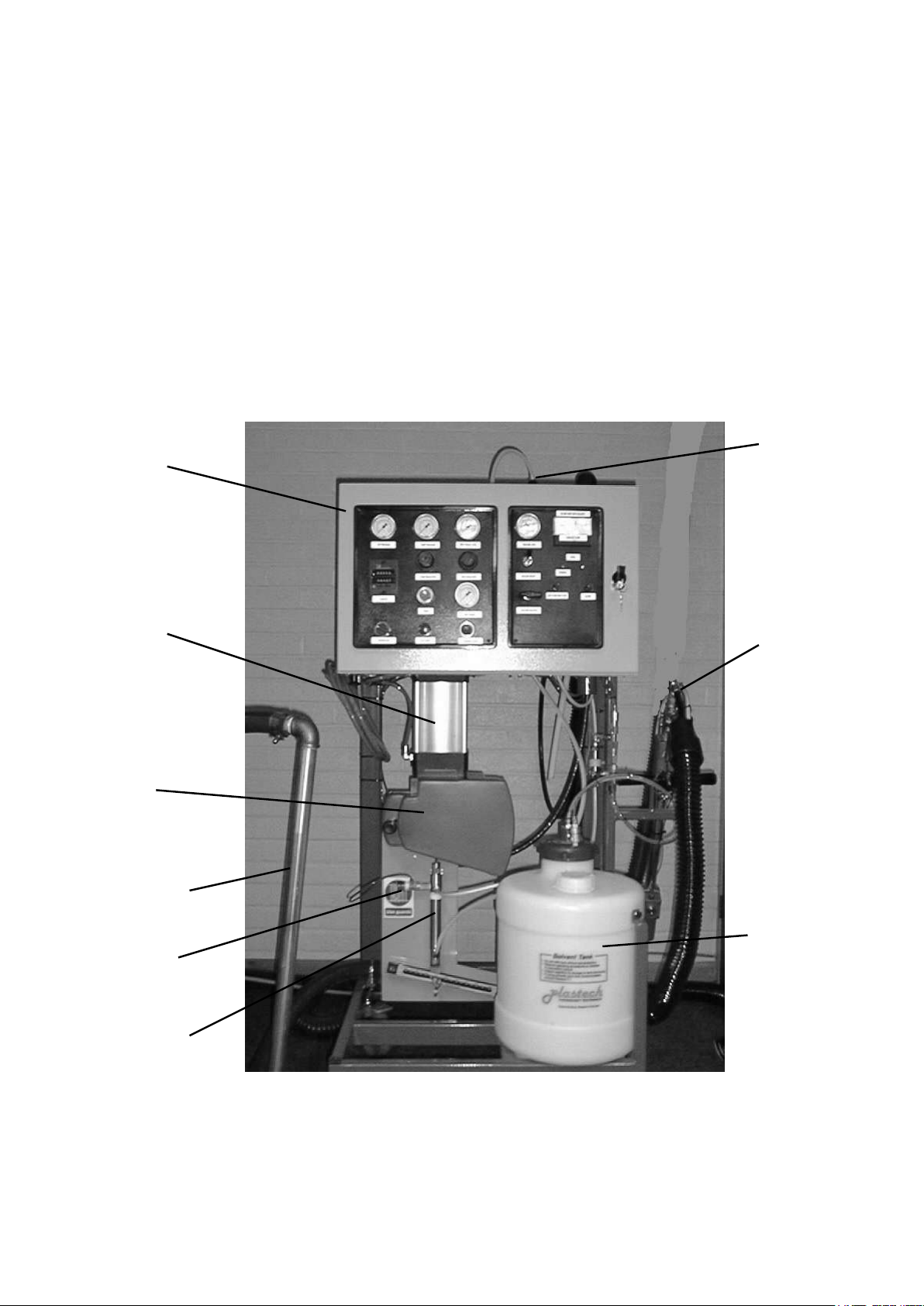
Catalyst Bottle
(behind)
Control
Cabinet
Pick up pipe
Injection
Head
Main Air
Cylinder
Catalyst Pump
Solvent Tank
Front
Guard
Catalyst Overpressure valve
Megaject Mk IV Overview
Introduction
This manual covers the operating and maintenance instructions of your particular model and
also includes details of options which may not be present on your machine. This will be
indicated at the relevant points.
This chapter shows the main machine components.
Megaject MK IV Issue 1_2 25/11/2003 Page 3 of 31
Page 4
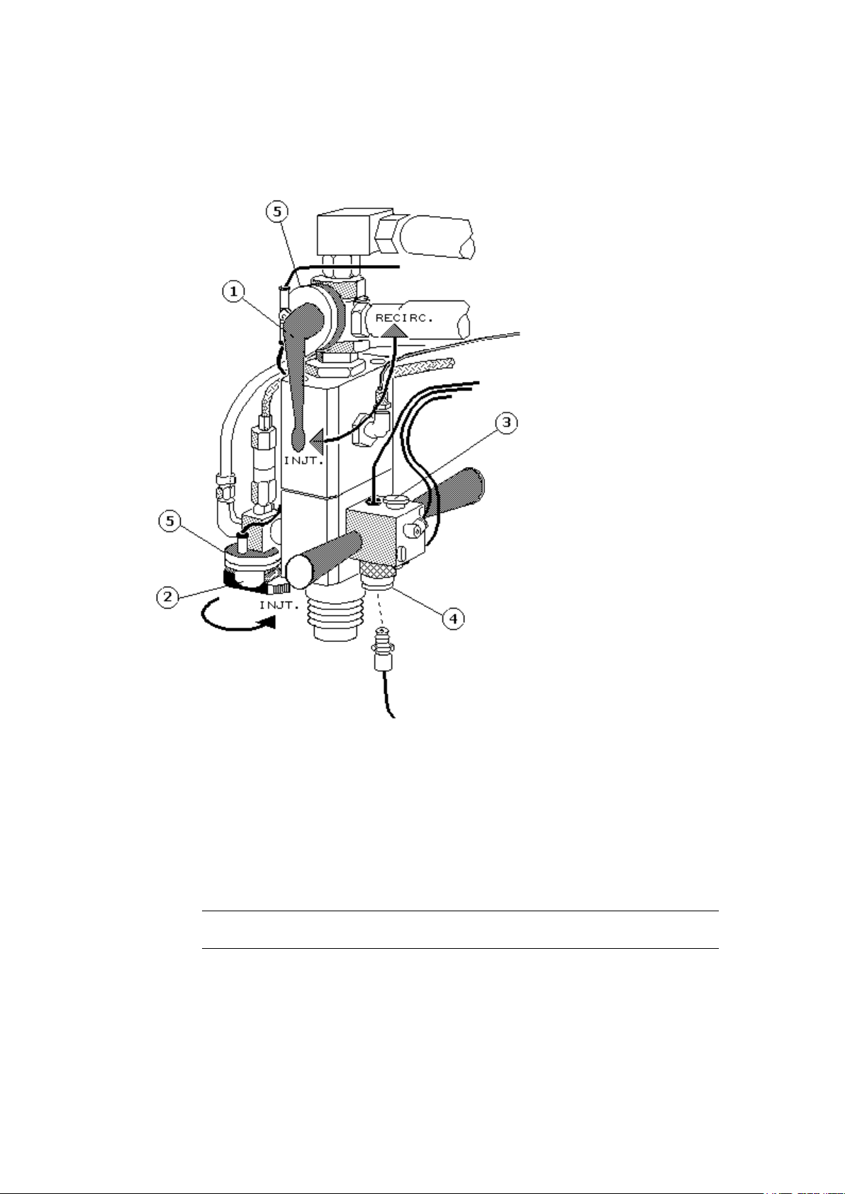
Injection Head
1. Resin recirculation valve. Swaps the resin stream between the injection and
the recirculation position. (90° movement)
2. Catalyst recirculation valve. Swaps the catalyst stream between the injection
and recirculation positions. (180° movement)
Note: Recirculation valves must be turned to their full extent for correct
operation i.e. 90° for resin and 180° for catalyst
3. Thumb Start Switch. Used to start machine for injection. Will only operate
when recirculation valves are in the injection position.
4. Autosprue Connector (for use with Autosprue option only)
5. Resin and Catalyst Interlock Switches. Check that both resin and catalyst
recirculation valves are in the inject position.
Megaject MK IV Issue 1_2 25/11/2003 Page 4 of 31
Page 5
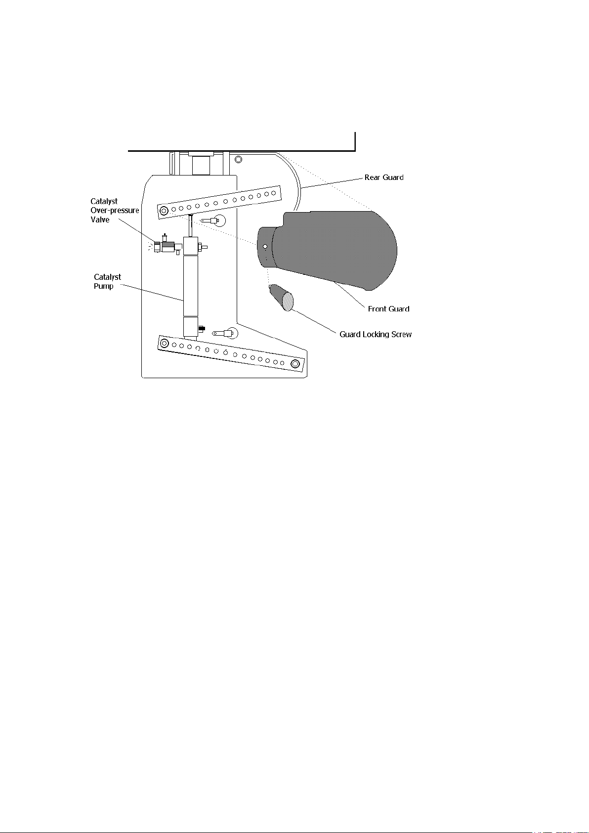
Machine Front Guard
1. Pump Front Guard. The linkage between the resin pump, catalyst pump and
the catalyst ratio arm is guarded to prevent any injury from moving machine
parts during the operation of the machine. The guard locking screw holds the
front guard in position. Removal of the guard will stop the machine.
Catalyst System
1. Catalyst Pump. Operated by the main resin pump. Catalyst ratio is indicated on
the ratio arms. On Megaject PF machines for use with phenolic resins (000067/68), two 316 stainless steel slave pumps are provided, with the catalyst ratio
determined by adding the two ratios.
2. Catalyst Overpressure Valve. If during the operation of the machine, the
catalyst system becomes blocked for any reason causing the catalyst to exceed a
pre-set pressure, the catalyst overpressure valve will activate and stop the
machine. Refer to Megaject Doctor for fault finding.
3. Catalyst Container. Catalyst store with feed and return pipes attached.
Megaject MK IV Issue 1_2 25/11/2003 Page 5 of 31
Page 6
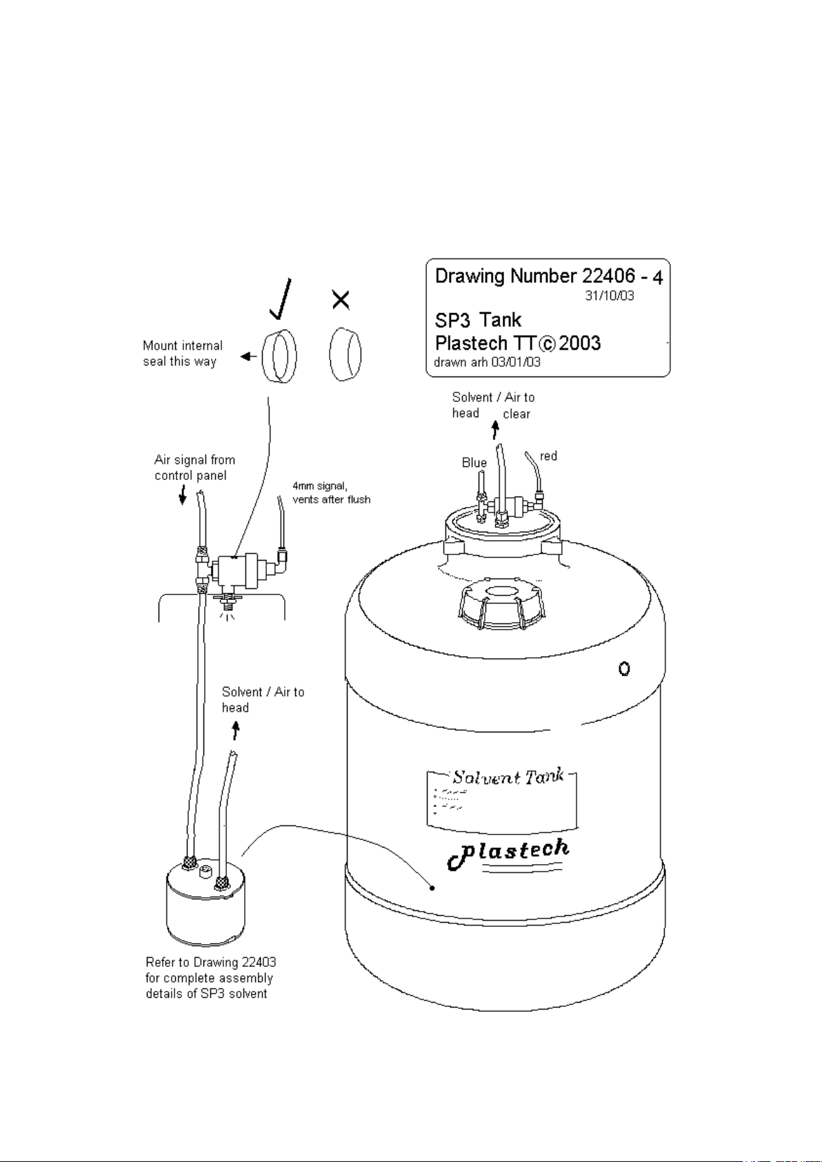
Solvent Pump NEW SP3
Note. With the introduction of the new Stainless Steel SP3 Solvent Pump System on
models supplied from January 2003 it is possible to upgrade previous machine models
with this unit. It is a simpler design over the former SP2 system and has greater
cleaning efficiency as there is greater throughput of air to the pump and thus to the
mixing head.
Megaject MK IV Issue 1_2 25/11/2003 Page 6 of 31
Page 7
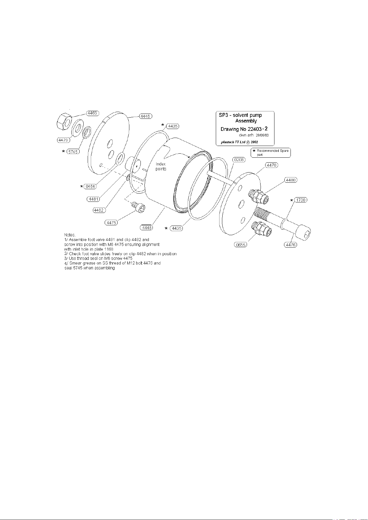
SP3 Assembly
Megaject MK IV Issue 1_2 25/11/2003 Page 7 of 31
Page 8
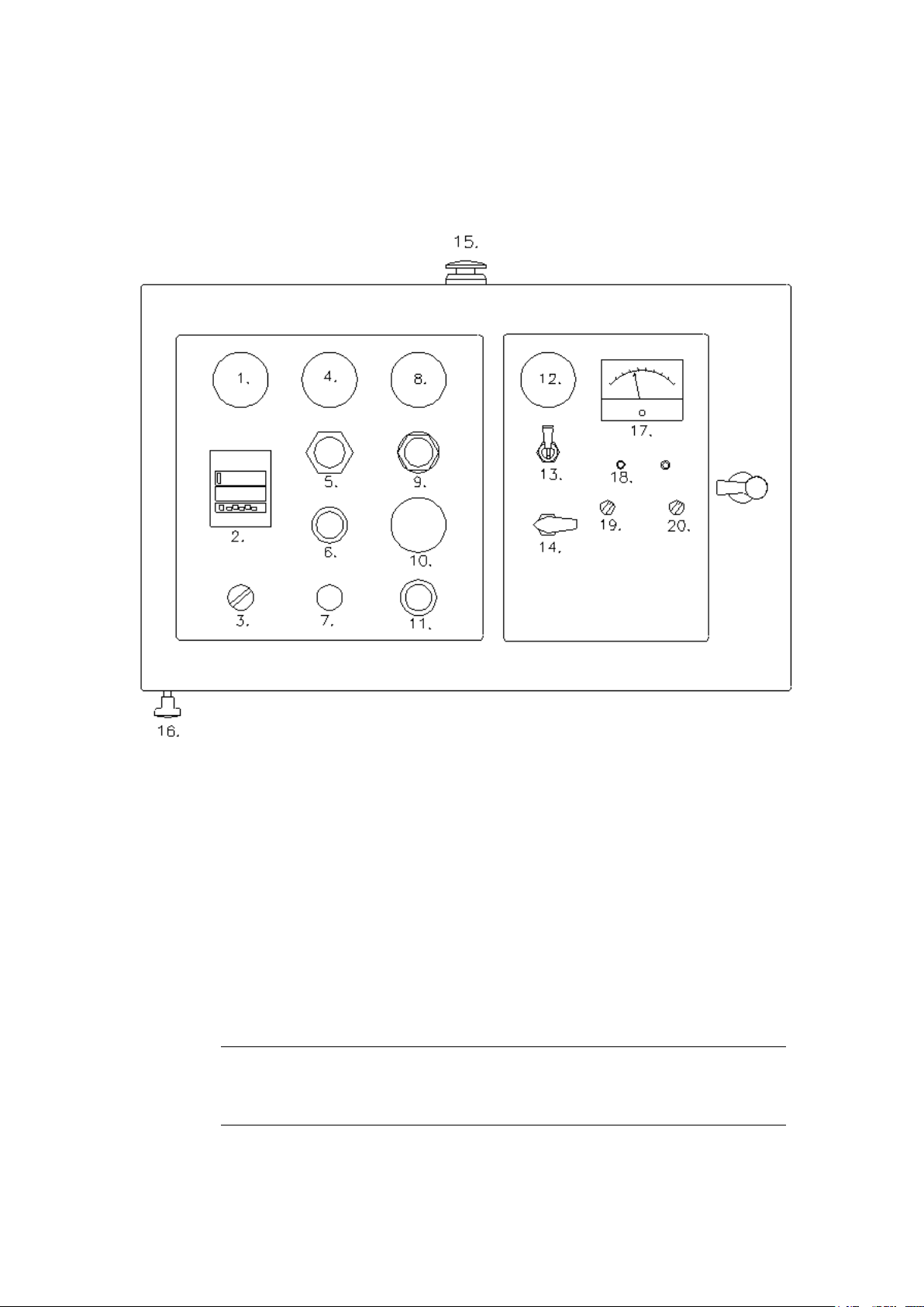
Operating Controls
Note: Some options may not appear on your machine
1. Incoming Air Pressure Gauge.
Indicates incoming air pressure to the machine.
2. Counters.
i) standard counter
Records the number of pump strokes of the machine. Each digit represents 100
cc’s (0.1 litres) of resin displaced.
ii) Pre-Determined Counter (PDC)
The pre-determining counter contains two readouts. The upper readout displays
the machine output count during injection. The lower readout displays the preset
count entered by the operator. Each digit represents 100 cc's (0.1 litres) of resin
displaced.
Megaject MK IV Issue 1_2 25/11/2003 Page 8 of 31
Page 9

To preset the counter, push white arrow lever on counter down and whilst
holding down - set the predetermined amount of strokes required with the
individual digit buttons and then release the white arrow lever. (Range 0-99.9
litres)
3. Recirculation Switch.
Turn to right to run the machine in recirculation mode (‘on’). Turn to left to stop
machine running in recirculation mode. (‘off’)
4. Pump Speed Pressure Gauge
Measures air pressure being sent to the resin pump air motor.
5. Pump Speed Pressure Regulator
Adjusts air pressure fed to the resin pump air motor, with reading shown on pump
speed pressure gauge.
6. Start Button (PDC machines only)
Begins machine operation. Will only operate when resin and catalyst recirculation
valves are in the inject position.
7. Air Purge Switch. (pull to operate)
Air purges excess resin\solvent from the injection head. Operates until pushed back
to stop.
OPTION: MPG Control Unit (automatically controls pump speed –
see Appendices)
8. MPG Preset Level Gauge
Indicates the maximum injection pressure selected by the operator
9. MPG Preset Regulator
Adjusts maximum injection pressure, with reading shown on MPG preset level
gauge.
10. Pump Signal gauge
Indicates pressure signal being sent to resin pump auto regulator. The lower
the pressure, the slower the pump speed.
11. Solvent Flush Button.
Activates the machine solvent flush cycle for approximately 30 seconds.
12. Mould Vacuum Level Gauge
Indicates level of vacuum achieved by the internal vacuum generator. With perfect
sealing of vacuum cavity, levels of -0.8 to -0.9 bar can be achieved.
13. Mould Vacuum On/Off.
Switches vacuum on/off. (Switch down for ON). Vacuum connection point is located
on rear of cabinet.
14. Mould Vacuum Isolator.
Isolates the vacuum generator from the remainder of the machine enabling air tight
vacuums to be held and read with the vacuum generator switched on or off. ( Switch
horizontal for isolate.)
15. Emergency Stop Button.
Removes all air pressure from the machine and deactivates the pull ‘on’ switch.
Megaject MK IV Issue 1_2 25/11/2003 Page 9 of 31
Page 10

16. Machine Pull ‘On’ Switch
Activates the machine. Deactivates in the event of either the emergency stop button
being pressed or if air supply falls below 1 bar.
OPTION: CATAL Catalyst Flow Monitor (see Appendices)
17. Analogue Flow Meter
Indicates level of catalyst flow in recirculation and injection modes
18. Green ‘ON’ LED
Indicates when the CATAL unit is operating. This will only occur when power
is supplied and the main pump is in motion.
19. Low\High Range Switch.
Adjusts scale resolution for differing catalyst flow rates.
20. Alarm Set Level
Adjusts the catalyst flow level at which an alarm will sound.
(on back of cabinet)
External power supply socket. (+/- 9V)
Remote LED large/small repeater socket (repeaters optional)
Whistle - not shown
Sounds when machine requires flushing (1 minute after end of injection). Operating solvent
flush button cancels whistle and resets timer.
Megaject MK IV Issue 1_2 25/11/2003 Page 10 of 31
Page 11

Commissioning & Set Up Procedures
CAUTION
Overalls and eye protection must be worn at all times during operation of the
machine.
CAUTION
Do not adjust the catalyst overpressure valve. If in any doubt about operation or
adjustment of any part of this machine please contact Plastech TT.
IMPORTANT NOTE
The resin pump upper collar must be filled with Plastech Pump Lubricant (supplied) to
clean and lubricate pump seals. Remove rear guard window and fill to approximately
10mm below top lip.
An oiler/lubricator must NOT be used in the air supply to the machine. Air must be
filterd and dry at 6-8 bar (85-115 psi).
The Megaject MK IV is tested and secured against leaks prior to despatch. It is
essential that the inlet tube connected to the resin pick up pipe and filter remain tight
and sealed at all times to prevent air ingress into the resin system.
We recommend the use of Acetone as the primary choice of cleaning solvent. If a
different solvent system is to be used please contact Plastech for details of changes
required.
Procedure
1. Connect earth lead from solvent tank to a suitable earth point. Ensure recirculation
switch is off. Connect 10mm air line (supplied) to workshop air supply. Pull the ON
switch down to the ON position. Observe incoming air pressure gauge reads a
minimum 6 bar at all times.
2. Place resin pick up pipe and resin recirculation pipe in resin container. Securely
anchor both pipes.
Note: If the machine is to be fed directly from a resin tank it may not be possible to use
the resin pick up pipe and filter supplied. A suitable in-line filtering system is
available from Plastech TT
3. Using the funnel provided, fill catalyst container to approx 3/4 full. For polyester
resin systems we recommend Acetyl Acetone Peroxide (AAP) catalyst (e.g.
Luperox 224).
Note: The use of MEKP is not recommended for RTM as product de-mould time is
significantly longer than with AAP. MEKP may also cause ‘gassing’ in the catalyst
system resulting in inaccurate catalyst flow and potential ‘wet spots’ in the
moulded part.
Megaject MK IV Issue 1_2 25/11/2003 Page 11 of 31
Page 12

Disclaimer: Plastech do not accept responsibility for the performance of Megaject
machines when using non recommended materials. For further information
contact Plastech TT.
4. Fill solvent tank following ‘Filling/Refilling Solvent Tank’ procedure.
5. Remove front guard and catalyst slave pump from the backplate. (DO NOT
remove any catalyst pump pipework.) Operate pump by hand until even resistance
is felt on both strokes and the lines are free of air. If difficulty is encountered
removing all air invert pump and continue operating by hand. Replace pump at
required percentage and refit guard.
6. Adjust pump output regulator to read 2 bar on the pump pressure gauge.
7. If MPG system is fitted, adjust preset regulator until preset level gauge reads 2
bar.
8. Ensure both resin and catalyst recirculation valves are in the recirculation position.
Turn recirculation switch ‘on’. Recirculate until a bubble free fluid flow is observed
at both the resin and catalyst containers and pump output is even on both
strokes. If air in the catalyst system persists turn the recirculation switch ‘off’ and
repeat procedure 6
Note: The recirculation switch should be used for recirculation only and must be turned
‘off’ when priming is complete.
9. Turn resin and catalyst recirculation valves to inject position.
10. Using either the start button (Predetermined counter machines only) or the thumb
start switch, pump 300cc’s (3 counts) into a waste container.
11. Pump 200 cc’s (2 counts) into a cup. DO NOT STIR.
12. The injection head must be flushed. Return resin and catalyst recirculation valves
to recirculate position. Place injection nozzle in a waste container. Operate the air
purge button to expel waste resin. Press the solvent flush button. This will reset
after approximately 30 seconds. Operate the air purge button to dry out the head
and mixer tube.
13. Check that resin in cup gels evenly and fully. If not, return to procedure 6.
Note: We strongly recommend that after injection, the recirculation valves are always
placed back into the recirculation position. This ensures that small amounts of
resin and/or catalyst do not leak forward into the head chambers. Major
movement of the pipes and/or day and night workshop temperature variations
could cause slight weeping into the head if the machine is idle and the
recirculation valves are not left in the recirculation position.
Megaject MK IV Issue 1_2 25/11/2003 Page 12 of 31
Page 13

Filling/Refilling Solvent Tank
Sufficient solvent levels are essential for the correct flushing of the machine. The solvent level
must not be allowed to fall below 5 litres as this may cause inefficient flushing.
Safety Note: Solvents are flammable. Care must be taken when handling solvents. Avoid
naked flames and sparks. Do not smoke in any area containing solvents.
When refilling solvent tank ensure earth clip is connected to dispensing container
Procedure
1. Remove small white filler cap from solvent tank. Refill tank to approx. 4/5 full.
Solvent level must always be high enough to cover top of pump chamber inside
the tank.
2. Replace cap
Megaject MK IV Issue 1_2 25/11/2003 Page 13 of 31
Page 14

Setting Catalyst Percentage
Megaject catalyst levels can be adjusted in the range 0.5% to 4.5% to suit differing resin
systems. This is achieved by movement of the catalyst slave pump along ratio arms directly
connected to the main resin pump.
Safety Note: Before altering catalyst percentage ensure that the resin and catalyst
recirculation valves are in the recirculation position. REMOVE air/power supply to the
machine. Any guards removed MUST be replaced before operation.
Procedure
1. Remove front guard where applicable
2. Remove ratio locking pins from the top and bottom joints of the catalyst slave
pump to the ratio arms by depressing the top of the pin, and then withdrawing.
3. Set catalyst slave pump to new required percentage on ratio arms and replace
top and bottom ratio locking pins.
4. Recirculate machine to ensure pump is correctly primed
5. If required, carry out a timed gel test, injecting approx 200 cc’s of resin into a
cup.
Megaject MK IV Issue 1_2 25/11/2003 Page 14 of 31
Page 15

Recirculating & Repriming
Recirculating
Recirculation of the machine should be carried out on a regular basis to ensure resin and
catalyst flows are even, free of air bubbles (observed through recirculation returns) and to
prevent sedimentation of any fillers/additives in the resin system.
Recirculation should be carried out at the start of each shift or if new material has been
added to either the resin or catalyst containers.
Procedure
1. Ensure both resin and catalyst recirculation valves are in the recirculate position.
2. Adjust pump pressure regulator until the pump pressure gauge reads approx. 2
bar. If MPG is fitted, adjust MPG preset level to approx. 1 bar.
3. Turn the recirculation switch to the ‘on’ position.
4. Allow machine to recirculate for required period. Ensure recirculating materials are
free of air bubbles and even on both pump strokes.
5. Turn recirculation switch to ‘off’ position.
Repriming
To be carried out when the operator wishes to change the resin/catalyst in a machine which
has already been commissioned.
Procedure
1. Remove pick up filter from fluid. Recirculate machine to empty fluid lines
2. To clean the lines and pump, place pick pipe in solvent container and recirculate
until clean solvent is observed at the recirculation pipe.
3. Place the recirculation pipe in a waste container. Place pick up pipe in new fluid.
Recirculate machine until all solvent is discharged and new fluid is observed at
the recirculation pipe.
4. Place recirculation pipe in fluid container with pick up pipe.
5. Continue recirculating until material is free of all air bubbles.
Note: If the new material is of a similar chemical type to the existing material,
then it may not be necessary to clean the system with solvent before loading the
new material.
Megaject MK IV Issue 1_2 25/11/2003 Page 15 of 31
Page 16

Injecting and Flushing
This procedure should be followed each time an injection or series of injections are carried
out.
Before Injection
Procedure
1. Check the pull ‘ON’ valve is on and the incoming air pressure gauge reads at least
6 bar.
2. Check recirculation switch is ‘off’.
3. Ensure there is sufficient resin, catalyst and solvent.
4. Check catalyst percentage is set to required level.
5. Adjust the pump pressure regulator to the required setting. (Suggested initial
setting – 1 bar)
Note: If MPG system is fitted, adjust the MPG preset regulator until the required
maximum injection pressure is indicated on the MPG preset level gauge.
(Suggested initial setting – 2 bar)
6. (PDC machines only) Set predetermined count to required count number. Press
counter reset button to set output count to zero.
Injection
Procedure
1. Place the injection nozzle into the mould injection port and hold.
2. Turn resin and catalyst recirculation valves to injection position.
3. Standard machine
press and hold thumb start button machine will inject until thumb start button is released.
OR
4. PDC machine
either:
i) press green start button machine will inject until predetermined count is reached.
or
ii) press and hold thumb start button machine will inject until thumb start button is released.
Megaject MK IV Issue 1_2 25/11/2003 Page 16 of 31
Page 17

Note: Pump pressure and MPG preset level (if fitted) can be adjusted during injection to
optimise the injection speed. DO NOT exceed the maximum safe injection
pressure for the selected mould.
5. Turn resin and catalyst recirculation valves to recirculation position.
6. Remove injection nozzle from mould
7. Place sprue plug in mould injection port.
Flushing
Procedure
1. Hold injection nozzle in waste container
2. Pull air purge button until excess resin is expelled.
3. Push solvent flush button. After approximately 30 seconds this button will reset.
The solvent flush button may be used a second time if necessary.
Note: If two or more injections are to be carried out consecutively, it may not be
necessary to flush the mixing head between shots. Approximately 1 minute after
the end of an injection, the whistle will sound indicating that the machine must be
flushed. Operating the solvent flush or continuing with the injection will cancel the
alarm.
Injection & Flushing when using an Autosprue™
When carrying out an injection through an Autosprue™, it is essential that the both the
Autosprue™ resin and signal pipes are connected to the injection head before starting
injection. The Autosprue™ MUST REMAIN CONNECTED to the injection head for the
flushing cycle. Only when flushing is complete may the Autosprue™ be disconnected.
Refer to Autosprue™ instructions for further details.
Megaject MK IV Issue 1_2 25/11/2003 Page 17 of 31
Page 18

Optimising output
Maximum output rate is dependant on various factors when pumping resin systems. The
following factors should be taken into account in order to achieve maximum mixed output.
1. Supply of air to the machine.
An air supply of sufficient pressure and volume flow rate must be supplied to the machine. To
check supply is sufficient, ensure that incoming air flow is at least 1200 litres/min at 8 bar
2. Resin viscosity.
High viscosity resins will reduce the potential output of any metering machine for a given
power input. Viscosity of the resin can be decreased by a) increasing the temperature. b)
Reducing filler loadings. c) Using viscosity modifiers
3. Pipe work restriction from pump to mixing head.
Fitting larger bore output hoses, or reducing the hose length can improve output of the
machine. This is an important criteria if long hoses (> 4 metres) or higher viscosity resins are
used.
4. Fillers
When using fillers, it is essential that the filler is well mixed and not allowed to settle out over
a period of time. A tank agitator may be used. Alternatively regularly recirculate the resin.
This may however reduce pump seal life. Filler particle sizes of 5m or less should be used. If
filter blockage is occurring, a larger mesh size should be used. Contact Plastech for further
details.
Megaject MK IV Issue 1_2 25/11/2003 Page 18 of 31
Page 19

Shutdown Instructions
Procedure
1. At the end of the day/shift switch off the machine air. Leave resin and catalyst
recirculation valves in the recirculation position.
2. The resin pump piston shaft should be parked at the bottom of its stroke. This ensures
any smears of resin on the pump shaft do not dry out causing excess seal wear
3. For shutdown periods, if any doubts exist about the stability of the resin system, it
should be reprimed with an unfilled, unaccelerated resin system. Once the system is full
of unaccelerated resin, pump approx 300cc’s (3 counts) of resin through the injection
head then flush. Do not leave the Megaject either empty or with a cleaning solvent in the
resin system. Under normal circumstances, catalyst may be left in the system for
extended periods.
4. If filled resin systems have been used filler may sediment at the bottom of the pump and
pipework. Under these circumstances a higher pump pressure may be required to start
the pump recirculating. If filler has formed a sediment around the bottom inlet ball valve
of the pump it may momentarily stick. In such circumstances continue to pump on
recirculation for 3 minutes which should ‘unstick’ the valve. The resulting flow will quickly
wash away sediment, allowing the pump to operate correctly. Should the problem
continue, the bottom resin pump ball valve must be serviced. (refer to service
instructions).
5. After a shutdown period, it is expedient to ensure the resin and catalyst systems are fully
primed. See commissioning instructions for details.
Megaject MK IV Issue 1_2 25/11/2003 Page 19 of 31
Page 20

Maintenance
The Megaject RTM Machine range has proved to be extremely reliable in service. To
maximise service life, it is important to keep the machine free from dirt and contamination
and follow correct procedures for use and maintenance as instructed in this manual.
Spares Ordering
To order spare parts for your machine, please indicate the relevant drawing ident number for
the part required.
Important Note: Read this section before attempting any maintenance of your
machine.
1. Eye Protection and protective clothing and gloves MUST be worn for all maintenance
operations.
2. Before carrying out any maintenance on this equipment, Remove air supply from machine.
3. Be aware that small residual pressures may exist in fluid lines even when the machine is
isolated from the air supply. Take care when removing fittings.
4. We recommend that if any work is to be carried out on the fluid sections (i.e. resin,
catalyst or solvent) that they are pumped empty prior to maintenance.
Maintenence Schedule.
(based on experience with standard recommended materials)
Every 1 tonne of resin pumped
1. Check general cleanliness of machine and ensure there are no leaks.
2. Check resin pump lubricant level
3. Clean resin filter. (Remove, clean with acetone, dry and replace).
4. Remove mixer shroud and check cleanliness of mixer tube.
Every 5 tonnes of resin pumped
1. Split injection mixing head. Examine internals for gelled resin or foreign objects. It
is not necessary to dismantle head Non Return Valves if the head appears to be in
good condition.
2. If MPG block is fitted, remove 4 M5 cap screws and examine parts. It is not
necessary to remove MPG diaphragm.
3. Remove catalyst filter. Clean with acetone, dry and replace.
Every 100 tonnes of resin pumped
1. Replace main resin pump seals
2. Replace mixer tube and mixer tube O ring.
3. Empty solvent tank, clean tank and filter.
Replacing Resin Pump Seals
Megaject MK IV Issue 1_2 25/11/2003 Page 20 of 31
Page 21

Important Safety Note All maintenance work on the machine must be carried out with the air supply
to the machine disconnected and due caution must be observed when opening all fluid and pneumatic
connections by using personal protection against possible internal residual pressures.
The following sections describe seal and internal fluid section maintenance procedures accompanied by
assembly and parts drawings.
Resin pump
Megaject MK IV Issue 1_2 25/11/2003 Page 21 of 31
Page 22

Resin pump service.
In order to service internal resin pump seals first pump out any resin from internals by placing system on
recirculation. It is also advisable to clean internals with solvent after resin removal before service. Do this
by recirculating 5 litres solvent through resin pump and finally pumping the solvent out of system.
Isolate machine from air supply
4.3.2 Piston Seal (0555) and Shaft seal (0549)
To access Piston seal (part 0555) remove 4 x M8 securing bolts (Part 0559). Slide Pump cylinder (0548)
and lower gold block assembly (0558) from piston.
The piston seal may now be removed by unscrewing seal retainer nut (0556). Replace seal observing that
the seal lip must face UP and valve ball (0554) is placed back into cage (0551)
NOTE If the shaft seal (0549) is to be replaced proceed further without re assembling the Piston and seal
The piston is re assembled in reverse order to the above. Observe that medium strength thread lock
should be used on piston bolt (0342)
To replace the shaft seal (0549) it is necessary to remove the top block (0546) from the machine. To do this
first remove the four M8 retaining bolts accessed from the underside of top block.. This will allow the top
block to be drawn down shaft away from the four square air motor pillars.
Using circlip pliers remove large circlip (0544). Remove washer (0545). Remove old seal (0549) and
discard. Install new seal and re assemble pump in reverse order. Note- O ring top and bottom seals (0547)
may be replaced during these service operations if found to be damaged.
Ensure pump assembly is evenly retightened with M8 tie bolts (0559)
When Pump is reinstalled in machine, renew pump seal lubricant in top seal block (0546)
Megaject MK IV Issue 1_2 25/11/2003 Page 22 of 31
Page 23

Replacing Catalyst Pump Seals
See drawings 22022/22042
Procedure
1. Remove catalyst pump from ratio arms. Disconnect inlet and outlet hoses at
swivel fittings
2. Unscrew bottom and top blocks from outer tube. Examine bottom block ball
bearing for pitting/damage. Replace if necessary.
3. Slide pump bore out of top block and remove from piston shaft
4. Replace pump bore outer tube O rings and lubricate using silicone grease.
5. Unscrew piston seal body from shaft. Examine piston ball and spring. Replace if
necessary.
6. Unscrew piston seal retainer. Remove and replace piston seal.
7. Remove top block from piston shaft. Unscrew top seal block from top block.
Remove shaft seals from top seal block and replace.
8. Remove felt washers and replace.
9. Reassembly is a reversal of the above procedure. When refitting the piston seal
retainer (part 0531) clean threads thoroughly. Place a small amount of Loctite
243 threadlock on the threads and screw in finger tight only.
Megaject MK IV Issue 1_2 25/11/2003 Page 23 of 31
Page 24

Servicing Injection Head
See drawing 22015
Note: During maintenance ensure resin and catalyst recirculation valves are in the
recirculate position. Avoid any cross contact of resin and catalyst.
Procedure
1. Remove air signal and solvent lines from the head. Using a 5mm allen key,
remove head block bolts. Split head into two sections. Remove head block O ring.
To remove NRV 3, first remove spring retaining pin at top of valve. Screw M8 bolt
partially into the valve and pull to remove from head.
2. NRV 2 may be unscrewed from the side port.
3. To remove NRV 1 unscrew from resin recirculation valve swivel fitting and then
remove from top head block.
4. To remove NRV 4, undo catalyst pipe swage fittings. Unscrew 3 way ball valve
from NRV 4. Unscrew NRV 4 from bottom head block.
5. Inspect all head block and NRV galleries. If hardened resin is evident, remove or
replace parts as necessary.
6. To disassemble all NRV’s, remove spring retaining pin. PTFE cone can be
replaced by removing spring from seat retainer.
7. When using a new PTFE cone, grind into NRV seat using thumb pressure only to
ensure a good seal. On reassembly a suitable hook must be used to stretch the
spring sufficiently to enable the retaining pin to be replaced.
8. Reassembly is a reversal of above procedures. Inspect head block O ring and
replace if necessary using a small amount of silicon grease to lubricate.
9. After reconnection of hoses and pipes, machine must be recirculated to expel air.
Note: We highly recommend catalyst and resin pipes are not removed from the recirculation
valves as leakage is inevitable.
Megaject MK IV Issue 1_2 25/11/2003 Page 24 of 31
Page 25

Mixer Tubes
See drawing 22020
Mixer tubes will only require replacement if partial or full gellation/sedimentation has
occurred in the injection head. They cannot be repaired and must be replaced.
To replace, remove mixer shroud from head. (If MPG option is fitted, signal pipes
must be removed first.) Remove mixer tube from shroud. Lightly grease new mixer
tube/shroud threads with silicon grease, ensure O ring is in position and replace in
mixer shroud.
Re-attach to mixer head and reconnect MPG pipes if applicable. (Blue pipe nearest to
mixer tube)
Resin and Catalyst Pipework
See drawing 22022/22028
If air is being drawn into the system, check integrity of all joints and connections
shown.
Joints should be tight and sealed correctly using a proprietary thread sealant. Do not
use sealant on cone and seat type joints.
Megaject MK IV Issue 1_2 25/11/2003 Page 25 of 31
Page 26

Catalyst Overpressure Valve
See drawing 22021
Under normal operational circumstances the catalyst overpressure valve is
maintenance free.
If catalyst leaks constantly from fitting (4), O rings (2) must be replaced
Important Note: It is essential that the internal spring tension is not disturbed in the event
of servicing this unit.
Procedure
To renew front O rings
1. Disconnect red signal pipe and clear overflow pipe. Unscrew whole assembly
from catalyst pump using 19 AF spanner on the forward stainless steel body
taking care of any small residual pressurised catalyst as thread seal is broken. DO
NOT disturb the spring tension end cap (0671).
2. Hold brass body (1035) and unscrew stainless steel body (1032). Pull shaft
(1034), and collar (1033) from body, replace O rings (0750) and reassemble.
Ensure shaft is reinserted with rounded end into the body.
3. Reassemble observing order illustrated in dwg. 22021. Ensure bodies (1032) and
(1035) are correctly screwed together using PTFE tape or similar thread sealant.
4. Reattach valve to catalyst pump using thread sealant.
5. Reprime catalyst system to remove any air from the system.
Machine Air Circuit
In case of problems, follow enclosed schematic diagrams to check the machine air circuits.
This circuit is specific to your machine. When contacting Plastech, please quote machine
serial number. (see front cover)
Megaject MK IV Issue 1_2 25/11/2003 Page 26 of 31
Page 27

Solvent Pump
See drawing 22036
Warning: Before commencing any work on the solvent system, ensure that the working
area is free from any sources of ignition.
To Test:
Turn on air supply to machine. Place injection nozzle in a waste container. Press solvent flush
button. Check solvent output from injection nozzle. Check inside tank during the flush cycle.
If air bubbles appear from the bottom of the solvent pump, either the foot valve or the
threaded joints in the solvent pump will require servicing.
To service solvent pump foot valve:
Procedure
1. Remove air supply from machine.
2. Remove 6mm blue air supply pipe. Mark position of 6mm clear solvent feed pipe
with tape. Unscrew fitting and remove pipe from top of solvent pump complete
with fitting cap and PTFE olive
3. Unscrew M8 cap screw holding tank to machine frame and remove tank.
4. Unscrew red solvent cap. Remove whole pump assembly. Solvent will drain from
the pump assembly as it is lifted. To completely empty solvent pump, turn upside
down and allow remaining solvent to pour out of solvent pipe fitting.
5. Secure pump body and unscrew solvent pump foot valve.
6. Examine filter for blockage and replace as necessary.
7. Using correct size drift, remove roll pin from foot valve.
8. Remove foot valve plunger. Replace O ring. Ensure correct size and grade O ring
is used.
9. Re-assemble foot valve using PTFE tape and/or silicone sealant on threads.
10. Replace pump assembly in tank and refit to machine frame.
11. Refit air supply and solvent feed pipes. Ensure that solvent feed pipe is pushed
through the fitting to the marked position and fitting olive is in the correct
position before tightening. Do not overtighten.
Megaject MK IV Issue 1_2 25/11/2003 Page 27 of 31
Page 28

Appendices
Mould Pressure Guard (MPG)
A fluid pump driven by a piston type air motor will deliver an amplified injection pressure.
For example; a standard machine uses an 11:1 air motor/pump ratio. This could result in the
actual pump pressure being amplified eleven times, thus 3 bar could become 33 bar when
the mould cavity becomes hydraulically full.
The MPG is designed to control the Megaject pump speed, and thus injection pressure, to
prevent injection pressure exceeding an adjustable preset limit.
Operation
Set the maximum injection pressure on the MPG preset level gauge using the MPG
regulator. (Suggested initial setting – 2 bar)
If the resin pressure is below the preset pressure, then the automatic regulator will
remain fully open allowing full mains pressure to the resin pump regulator.
If the resin pressure exceeds the preset level, the ‘MPG signal pressure’ will reduce
proportionally closing the automatic regulator and limit air pressure to the resin pump
regulator. This slows or stops the resin pump, reducing resin pressure until it
matches the preset level. During operation, a small leak of air will occur from the
MPG sensor block. This is normal.
The MPG preset level may be adjusted during an injection to achieve optimum pump
output speed at the safest injection pressure.
Several factors will affect the optimum setting of the MPG regulator, e.g. fibre volume
fraction, mould size and rigidity, resin viscosity, required resin delivery rate etc.
Megaject MK IV Issue 1_2 25/11/2003 Page 28 of 31
Page 29

CATAL Catalyst Monitoring System
The CATAL catalyst monitoring system provides a visual and audible indication of catalyst flow during
injection and recirculation.
Operation
Connect the Catal Power Supply to the Megaject. The connection is via the 5 pin DIN
socket located on the back of the Megaject control cabinet.
The Catal power supply is rated at 110 or 240v input, +/- 9V output. If you have the
incorrectly rated unit for your supply, please contact Plastech TT.
The catalyst flow monitor will operate only whilst the machine is pumping
Catalyst flow is indicated on the analogue gauge.
The sensor has been factory set to catalyst flow ranges typical in normal RTM
application i.e. 5kg/minute resin mix at 2% cat. ratio. When the flow range switch is
switched to ‘LOW FLOW’ position the system will indicate a catalyst flow as low as
6ml/minute (e.g. resin mix output of 1kg/minute at 0.5% catalyst). If indicating
towards the maximum level, move the range switch to ‘HIGH FLOW’. If meter
reading reaches top of meter, the sensor element may be moved upwards to
accommodate the higher flow. (see diagram).
It is not necessary to keep readjusting the sensor element. It is simply a coarse
adjustment setting depending on your normal output levels.
The operator can observe the flow rate of catalyst over a wide range of pump speeds
and percentage settings. The audible alarm can be set by turning the alarm setting
control clockwise from zero to a point just below the ‘running level’ (e.g. giving an
alarm when the catalyst flow drops below this setting).
Megaject MK IV Issue 1_2 25/11/2003 Page 29 of 31
Page 30

Resin Heaters
Important Note
It is essential that resin heaters are not left turned on with stationary resin in the system.
Uncatalysed resin will eventually cure at elevated temperatures and block the heater
channels..
Whilst the resin heater is on, the machine MUST be either recirculating or injecting.
At the end of a shift, turn off the resin heater and continue to recirculate the machine until
the resin has cooled to room temperature. It is then safe to turn off the machine.
Megaject MK IV Issue 1_2 25/11/2003 Page 30 of 31
Page 31

Revision History
Manual
Date
Revision
Code
Revised Content
MKIV
23/2/00
1_0
New Manual – revision from previous sections
MKIV Doctor
23/2/00
1_0
Revision code changed
Drawing Number
Revision
22001
3
22041
4
22042
7
22022
9
22015
11
22020
10
22021
3
22028
6
22036
9
22034
3
22039
2
Air Circuit
S/N
Revision codes appear on the front page of the manual.
e.g. Sprint1_0
Sprint = Machine Name
1 = major revision 1
0 = minor revision 0
Drawings included in this manual
Megaject MK IV Issue 1_2 25/11/2003 Page 31 of 31
 Loading...