

Page 1

MANUAL
MAGNUM VENUS PLASTECH
INNOVATOR MEGAJECT 3250 (8000) Rev: 05/2011
INNOVATOR MEGAJECT 5000 (8001)
Page 2

Innovator Megaject
Operations Manual
CORPORATE HEADQUARTERS and MANUFACTURING
5148 113th Ave. N. *Clearwater, FL 33760 * Tel 727-573-2955 * Fax 727-571-3636
TECHNOLOGY CENTER / WEST COAST MANUFACTURING
1862 Ives Ave. * Kent, WA 98032 * Tel 253-854-2660 * Fax 253-854-1666
MVP Plastech UK
Chilsworthy Beam, Gunnislake, Cornwall, PL18 9AT UK, * Tel:+44 (0) 1822 832621
Fax: +44 (0) 1822 833999
MAGNUM VENUS PLASTECH
2
Innovator Megaject Manual
Page 3

Innovator Megaject
Operations Manual
Table of Contents:
SAFETY WARNINGS
SECTION 1: GETTING STARTED
SECTION 2: CONTROL BOX INSTRUCTIONS
SECTION 3: OPERATING PROCEDURES
SECTION 4: FLUID SECTION MAINTENANCE & REPAIR
SECTION 5: CATALYST PUMP MAINTENANCE & REPAIR
SECTION 6: PATRIOT POWERHEAD
SECTION 7: INJECTION HEAD & MIXER ASSEMBLY
SECTION 8: SP4 SOLVENT PUMP ASSEMBLY
SECTION 9: PARTS DRAWINGS
SECTION 10: REVISON INFORMATION
MAGNUM VENUS PLASTECH
3
Innovator Megaject Manual
Page 4

The page is left blank intentionally
MAGNUM VENUS PLASTECH
4
Innovator Megaject Manual
Page 5

SAFETY WARNINGS INSTRUSTIONS:
OPERATING YOUR POLYESTER SYSTEM SAFELY
1. Introduction
Any tool, if used improperly, can be dangerous. Safety is ultimately the responsibility of
those using the tool. In like manner, safe operation of polyester processes is the
responsibility of those who use such processes and those who operate the equipment.
This manual outlines procedures to be followed in conducting polyester operations
safety. This system has been specifically designed for use of Polyester Resin, Gel-Coat,
and Methyl Ethyl Ketone Peroxides (MEKP) applications. Other formulations or blends
considered for use in this equipment is strictly prohibited without the expressed consent
by Magnum Venus Plastech Inc. Magnum Venus Plastech cannot eliminate every
danger nor foresee every circumstance that might cause an injury during equipment
operation. Some risks, such as the high pressure liquid stream that exits the spray tip,
are inherent to the nature of the machine operation and are necessary to the process in
order to manufacture the end-product. For this reason, ALL personnel involved in
polyester operations should read and understand the Safety Manual. It is very important
for the safety of employees involved in the operation that equipment operators,
maintenance and supervisory personnel understand the requirements for safe operation.
Each user should examine his own operation, develop his own safety program and be
assured that his equipment operators follow correct procedures. Magnum Venus
Plastech hopes that this manual is helpful to the user and recommends that the
precautions in this manual be included in any such program. Magnum Venus Plastech
recommends this Safety Manual remain on yo ur equipment at all times for your
personnel safety. In addition to the manual, Magnum Venus Plastech recommends that
the user consult the regulations established under the Occupational Safety & Health Act
(OSHA), particularly the following sections:
1910.94 Pertaining to Ventilation.
1910.106 Pertaining to flammable liquids
1910.107 Pertaining to spray finishing operations, particularly Paragraph (m) Organic
Peroxides and Dual Component Coatings.
Other standards and recognized authorities to consult are the National Fire Protection
Association (NFPA) bulletins as follows:
NFPA No.33 Chapter 14, Organic Peroxides and Dual Component Materials
NFPA No.63 Dust Explosion Prevention
NFPA No.70 National Electrical Code
NFPA No.77 Static Electricity
NFPA No.91 Blower and Exhaust System
NFPA No.654 Plastics Industry Dust Hazards
MAGNUM VENUS PLASTECH
5
Innovator Megaject Manual
Page 6

Type of Fire Extinguishing equipment recommended: Fire Extinguisher – code ABC,
rating number 4a60bc.
Extinguishing Media – Foam, Carbon Dioxide, Dry Chemical, Water Fog.
Copies of the above bulletins are available, at a nominal charge from:
National Fire Protection Association
470 Atlantic Avenue
Boston, MA 02210
Research Report No.11 of the American Insurance Association deal with “Fire,
Explosion and Health Hazards of Organic Peroxides”. It is published by:
American Insurance Association
85 John Street
New York, NY 10038
Local codes and authorities also have standards to be followed in the operation of your
spraying equipment. Your insurance carrier will be helpful in answering questions that
arise in your development of safe procedures.
1.2 Personal Safety Equipment
Magnum Venus Plastech recommends the following Personal Safety Equipment for
conducting safe operations of the Polyester Systems:
Magnum Venus Plastech recommends that the user consult the state and local
regulations established for all Safety equipment listed.
2.0 Material Safety
2.1 Hazards Associated with Laminating Operations
The major hazards which should be guarded against in polyester laminating operations
are those associated with:
1. The flammability and explosion dangers of the catalyst normally used – Methyl Ethyl
Ketone Peroxide (MEKP).
2. The flammability dangers of clean-up solvents sometimes used (Magnum Venus
Plastech recommends that clean-up solvents be non-flammable), and of resin diluents
used, such as styrene.
3. The flammability dangers of catalyst diluents, if used. (Magnum Venus Plastech
recommends that catalyst not be diluted.
4. The flammability dangers of the uncured liquid resins used.
5. The combustibility dangers of the cured laminate, accumulations of over spray, and
laminate sandings.
6. The toxicity dangers of all the chemicals used in laminating operations with respect to
ingestion, inhalation and skin and eye hazards.
MAGNUM VENUS PLASTECH
6
Innovator Megaject Manual
Page 7

2.2 Catalyst (Methyl Ethyl Ketone Peroxide)
MEKP is among the more hazardous materials found in commercial channels. The safe
handling of the “unstable (reactive)” chemicals presents a definite challenge to the
plastics industry. The highly reactive property which makes MEKP valuable to the
plastics industry in producing the curing reaction of polyester resins also produces the
hazards which require great care and caution in its storage, transportation, handling,
processing and disposal. MEKP is a single chemical. Various polymeric forms may exist
which are more or less hazardous with respect to each other. These differences may
arise not only from different molecular structures (all are, nevertheless, called “MEKP”)
and from possible trace impurities left from the manufacture of the chemicals, but may
also arise by contamination of MEKP with other materials in its storage or use. Even a
small amount of contamination with acetone, for instance, may produce an extremely
shock-sensitive and explosive compound.
Contamination with promoters or materials containing promoters, such as
laminate sandings, or w ith any readily oxidizing material, such as brass or iron,
will cause exothermic “redox” reactions which can become explosive in nature.
Heat applied to MEKP, or heat build-up from contamination reactions can cause it
to reach what is called its Self-Accelerating Decomposition Temperature (SADT).
Researchers have reported measuring pressure rates-of-rise well in excess of 100,000
psi per second when certain MEKP’s reach their SADT. (For comparison, the highest
pressure rate-of-rise listed in NFPA Bulletin NO.68, “Explosion Venting”, is 12,000 psi
per second for an explosion of 12% acetylene and air. T he maximum value listed for a
hydrogen explosion is 10,000 psi per second. Some forms of MEKP, if allowed to reach
their SADT, will burst even an open topped container. This suggests that it is not
possible to design a relief valve to vent this order of magnitude of pressure rate-of-rise.
The user should be aware that any closed container, be it a pressure vessel, surge
chamber, or pressure accumulator, could explode under certain conditions. There is no
engineering substitute for care by the user in handling organic peroxide catalysts. If, at
any time, the pressure relieve valve on top of the catalyst tank should vent, the area
should be evacuated at once and the fire department called. The venting could be the
first indication of a heat, and therefore, pressure build-up that could eventually lead to an
explosion. Moreover, if a catalyst tank is sufficiently full when the pressure relief valve
vents, some catalyst may spray out, which could cause eye injury. For this reason, and
many others, anyone whose job puts them in an area where this vented spray might go,
should always wear full eye protection even when laminating operations are not taking
place.
Safety in handling MEKP depends to a great extent on employee education, proper
safety instructions and safe use of the chemicals and equipment. Workers should be
thoroughly informed of the hazards that may result form improper handling of MEKP,
especially in regards to contamination, heat, friction and impact. They should be
thoroughly instructed regarding the proper action to be taken in the storage, use and
disposal of MEKP and other hazardous materials used in the laminating operation. In
addition, users should make every effort to:
A. Store MEKP in a cool, dry place in original containers away from direct sunlight and
away from other chemicals.
B. Keep MEKP away from heat, sparks and open flames.
MAGNUM VENUS PLASTECH
7
Innovator Megaject Manual
Page 8

C. Prevent contamination of MEKP with other materials, including polyester over spray
and sandings, polymerization accelerators and promoters, brass, aluminum and nonstainless steels.
D. Never add MEKP to anything that is hot, since explosive decomposition may result.
E. Avoid contact with skin, eyes and clothing. Protective equipment should be worn at all
times. During clean-up of spilled MEKP, personal safety equipment, gloves and eye
protection must be worn. Fire fighting equipment should be at hand and ready.
F. Avoid spillage, which can heat up to the point of self-ignition.
G. Repair any leaks discovered in the catalyst system immediately, and clean up the
leaked catalyst at once in accordance with the catalyst manufacturer’s instructions.
H. Use only original equipment or equivalent parts from Magnum Venus Plastech in the
catalyst system (i.e.: hoses, fitting, etc.) because a dangerous chemical reaction may
result between substituted parts and MEKP.
I. Catalyst accumulated from the purging of hoses or the measurement of fluid output
deliveries should never be returned to the supply tank, such catalyst should be diluted
with copious quantities of clean water and disposed of in accordance with the catalyst
manufacturer’s instructions.
The extent to which the user is successful in accomplishing these ends and any
additional recommendations by the catalyst manufacturer determines largely the safety
that will be present in his operation.
2.3 Clean-Up Solvents and Resin Diluents
WARNING
A hazardous situation may be present in your pressurized fluid system!
Hydrocarbon Solvents can cause an explosion when used with aluminum or
galvanized components in a closed (pressurized) fluid system (pump, heaters,
filters, valves, spray guns, tanks, etc.). T he explosion could cause serious injury,
death and/or substantial property damage. Cleaning agents, coatings, paints, etc.
may contain Halogenated Hydrocarbon Solvents. Some Magnum Venus Plastech
spray equipment includes aluminum or galvanized components and will be
affected by Halogenated Hydrocarbon Solvents.
A. There are three key elements to the Halogenated Hydrocarbon (HHC) solvent hazard.
a. The presence of HHC solvents. 1,1,1 – Trichloroethane and Methylene
Chloride are the most common of these solvents. However, other HHC
solvents are suspect if used; either as part of paint or adhesives formulation, or
for clean-up flushing. b. Aluminum or Galvanized Parts. Most handling
equipment contains these elements. In contact with these metals, HHC
solvents could generate a corrosive reaction of a catalytic nature.
b. Equipment capable of withstanding pressure. When HHC solvent contact
aluminum or galvanized parts inside a closed container such as a pump, spray
gun, or fluid handling system, the chemical reaction can, over time, result in a
build-up of heat and pressure, which can reach explosive proportions.
MAGNUM VENUS PLASTECH
8
Innovator Megaject Manual
Page 9

When all three elements are present, the result can be an extremely violent explosion.
The reaction can be sustained with very little aluminum or galvanized metal; any amount
of aluminum is too much.
A. The reaction is unpredictable. Prior use of an HHC solvent without incident (corrosion
or explosion) does NOT mean that such use is safe. These solvents can be dangerous
alone (as a clean-up or flushing agent) or when used as a component or a coating
material. There is no known inhibitor that is effective under all circumstances.
Furthermore, the mixing of HHC solvents with other materials or solvents, such as
MEKP, alcohol, and toluene, may render the inhibitors ineffective.
B. The use of reclaimed solvents is particularly hazardous. Reclaimers may not add any
inhibitors. Also, the possible presence of water in reclaimed solvents could feed the
reaction.
C. Anodized or other oxide coatings cannot be relied upon to prevent the explosive
reaction. Such coatings can be worn, cracked, scratched, or too thin to prevent contact.
There is no known way to make oxide coatings or to employ aluminum alloys, which will
safely prevent the chemical reaction under all circumstances.
D. Several solvent suppliers have recently begun promoting HHC solvents for use in
coating systems. The increasing use of HHC solvents is increasing the risk. Because of
their exemption from many State Implementation Plans as Volatile Organic Compounds
(VOC’s), their low flammability hazard, and their not being classified as toxic or
carcinogenic substances, HHC solvents are very desirable in many respects.
WARNING: Do not use Halogenated Hydrocarbon solvents in pressurized fluid
systems having aluminum or galvanized wetted parts.
NOTE: Magnum Venus Plastech is aware of NO stabilizers available to prevent
Halogenated Hydrocarbon solvents from reaction under all conditions w ith
aluminum components in closed fluid system. TAKE IMMEDIATE ACTION…
Halogenated Hydrocarbon solvents are dangerous w hen used with aluminum
components in a closed fluid system.
A. Consult your material supplier to determine whether your solvent or coating contains
Halogenated Hydrocarbon Solvents.
B. Magnum Venus Plastech recommends that you contact your solvent supplier
regarding the best non-flammable clean-up solvent with the heat toxicity for your
application.
C. If, however, you find it necessary to use flammable solvents, they must be kept in
approved, electrically grounded containers.
D. Bulk solvent should be stored in a well-ventilated, separate building, 50 feet away
from your main plant.
E. You should allow only enough solvent for one day’s use in your laminating area.
F. “NO SMOKING” signs must be posted and observed in all areas of storage or where
solvents and other flammable materials are used.
MAGNUM VENUS PLASTECH
9
Innovator Megaject Manual
Page 10

G. Adequate ventilation (as covered in OSHA Section 1910.94 and NFPA No.91) is
important wherever solvents are stored or used, to minimize, confine and exhaust the
solvent vapors.
H. Solvents should be handled in accordance with OSHA Section 1910.106 and
1910.107.
2.4 Catalyst Diluents
Magnum Venus Plastech spray-up and gel-coat systems currently produced are
designed so that catalyst diluents are not required. Magnum Venus Plastech, therefore,
recommends that diluents not be used. This avoids the possible contamination which
could lead to an explosion due to the handling and mixing of MEKP and diluents. In
addition, it eliminates any problems from the diluents being contaminated through rust
particles in drums, poor quality control on the part of the diluents suppliers, or any other
reason. If, however, diluents are absolutely required, co ntact your catalyst supplier and
follow his instructions explicitly. Preferable, the supplier should premix the catalyst to
prevent possible “on the job” contamination while mixing.
WARNING
If diluents are not used, it should be remembered that catalyst spillage, gun, hose
and packing leaks are potentially more hazardous, since each drop contains a
higher concentration of catalyst, and therefore will react quicker with over spray
and the leak.
2.5 Cured Laminate, Overspray and Laminate Sandings Accumulation
A. Remove all accumulations of overspray, FRP sandings, etc. from the building as they
occur. If this waste is allowed to build up, spillage of catalyst is more likely to start a fire,
in addition, the fire would burn hotter and longer.
B. Floor coverings, if used, should be non-combustible.
C. Spilled or leaked catalyst may cause a fire if it comes in contact with an FRP product,
over-sprayed chop or resin, FRP sandings or any other material with MEKP.
To prevent this spillage and leakage, you should:
1. Maintain your Magnum Venus Plastech System. Check the gun several times daily for
catalyst and resin packing or valve leaks. REPAIR ALL LEAKS IMMEDIATELY.
2. Never leave the gun hanging over, or lying inside the mold. A catalyst leak in this
situation would certainly damage the part, possibly the mold, and may cause a fire.
3. Inspect resin and catalyst hoses daily for wear or stress at the entry and exits of the
boom sections and at the hose and fittings. Replace if wear or weakness is evident or
suspected.
4. Arrange the hoses and fiberglass roving guides so that the fiberglass strands DO NOT
rub against any of the hoses at any point. If allowed to rub, the hose will be cut through,
causing a hazardous leakage of material which could increase the danger of fire. Also,
the material may spew onto personnel in the area.
MAGNUM VENUS PLASTECH
10
Innovator Megaject Manual
Page 11

2.7 Toxicity of Chemicals
A. Magnum Venus Plastech recommends that you co nsult OSHA Sections 1910.94,
1910.106, 1910.107 and NFPA No.33, Chapter 14, and NFPA No.91.
B. Contact your chemical supplier(s) and determine the toxicity of the various chemicals
used as well as the best methods to prevent injury, irritation and danger to personnel.
C. Also determine the best methods of first aid treatment for each chemical used in your plant.
2.8 Treatment of Chemical Injuries
Great care should be used in handling the chemicals (resins, catalyst and solvents) used
in polyester systems. Such chemicals should be treated as if they hurt yo ur skin and
eyes and as if they are poison to your body. For this reason, Magnum Venus Plastech
recommends the use of protective clothing and eye wear in using polyester systems.
However, users should be prepared in the event of such an injury. Precautions include:
1. Know precisely what chemicals you are using and obtain information from your
chemical supplier on what to do in the event the chemical gets onto your skin or into
the eyes, or is swallowed.
2. Keep this information together and easily available so that it may be used by those
administering first aid or treating the injured person.
3. Be sure the information from your chemical supplier includes instructions on how to
treat any toxic effects the chemicals have.
WARNING
Contact your doctor immediately in the event of any injury and give him the
information you have collected. If your information includes first aid instructions,
administer first aid immediately while you are contacting your doctor.
Fast treatment of the outer skin and eyes that contact such chemicals generally includes
immediate and thorough washing of the exposed skin and immediate and continuous
flushing of the eyes with lots of clean water for at least 15 minutes or more. These
general instructions of first aid treatment, however, may be incorrect for some chemicals;
that is why you must know the chemicals and treatment before an accident occurs.
Treatment for swallowing a chemical frequently depends upon the nature of the
chemical.
NOTE: Refer to your System User Manual for complete and detailed operating
instructions and service information.
MAGNUM VENUS PLASTECH
11
Innovator Megaject Manual
Page 12

3.0 Equipment Safety
WARNING
Magnum Venus Plastech suggest that personal safety equipment such as EYE
GOGGLES, GLOVES, EAR PROTECTION, and RESPIRATORS be worn when
servicing or operating this equipment. Ear protection should be w orn when
operating a fiberglass chopper to protect against hearing loss since noise levels
can be as high as 116 dB (decibels). T his equipment should only be operated or
serviced by technically trained personnel!
WARNING
Never place fingers, hands, or any body part near or directly in front of the spray
gun fluid tip. T he force of the liquid as it exits the spray tip can cause serious
injury by shooting liquid through the skin. NEVER LOOK DIRECTLY INTO THE
GUN SPRAY TIP OR POINT T HE GUN AT OR NEAR ANOTHER PERSON. (TREAT
THE GUN AS IF IT WERE A LOADED PISTOL.)
3.1 Emergency Stop Procedures
The following steps should be followed in order to stop the machinery in an emergency
situation
1. The ball valve located where the air enters the power head of the resin pump, should
be moved to the “OFF” or closed position. To do this, simply rotate the lever on the
ball valve 90 degrees. Doing this will cause all the system air to bleed out of the
system in a matter of a few seconds, making the system incapable of operating
NOTE: Step 2 is a precautionary step and should be followed whenever the
above mentioned ball valve is activated to the stop mode. Failure to do so, can
damage the regulators and components on reactivating to the “ON” position.
2. Turn all system regulators to the “OFF” position (counter-clockwise) position
NOTE: Verify that the Catalyst relief line, located on the catalyst manifold, and
the resin return line, located on the resin filter, are secured relieving catalyst and
resin fluid pressure.
3. Catalyst pressure in the catalyst pump can be eliminated by rotating the ball valve on
the catalyst manifold 90 degrees to the “open” or “on” position.
Note: The “open” or “on” position is when the ball valve handle is parallel (in line)
with the ball valve body. The “closed” or “off” position is when the ball valve
handle is perpendicular (across) the ball valve body.
4. Resin pressure in the resin pump can be eliminated by rotating the ball valve on the
resin filter 90 degrees to the “open” or “on” position. Place a container under the ball
valve to catch any resin that is ejected out of the valve.
MAGNUM VENUS PLASTECH
12
Innovator Megaject Manual
Page 13

3.2 Grounding
Grounding an object means providing an adequate path for the flow of the electrical
charge from the object to the ground. An adequate path is one that permits charge to
flow from the object fast enough that it will not accumulate to the extent that a spark can
be formed. It is not possible to define exactly what will be an adequate path under all
conditions since it depends on many variables. In any event, the grounding means
should have the lowest possible electrical resistance. Grounding straps should be
installed on all loose conductive objects in the spraying area. This includes material
containers and equipment. Magnum Venus Plastech recommends grounding straps be
made of AWG No.18 stranded wire as a minimum and the larger wire be used where
possible. NFPA Bulletin No77 states that the electrical resistance of such a leakage
path may be as low as 1 meg ohm (10 ohms) but that resistance as high as 10,000 meg
ohms will produce an adequate leakage path in some cases. Whenever flammable or
combustible liquids are transferred from one container to another, or from one container
to the equipment, both containers or container and equipment shall be effectively
bonded and grounded to dissipate static electricity. For further information, see
National Fire Protection Association ( NFPA) 77, titled “Recommended Practice on
Static Electrical”. Refer especially to section 7-7 titled “Spray Application of Flammable
and Combustible Materials”. Check with local codes and authorities for other specific
standards that might apply to your application. NEVER USE HARD MATERIALS SUCH
AS WIRE, PINS, ETC., TO CLEAR A PLUGGED GUN. HARD MATERIALS CAN
CAUSE PERMANENT DAMAGE. DAB WITH A BRISTLE BRUSH, BLOW
BACKWARDS WITH AIR UNTIL CLEAR WHILE WEARING A PROTECTIVE EYE
SHIELD. REPEAT AS MANY TIMES AS NECESSARY. DO NOT PERFORM ANY
MAINTENANCE OR REPAIRS UNTIL YOU HAVE FOLLOWED THE PRECAUTIONS
STATED ABOVE. IF YOU, AS AN EQUIPMENT OPERATOR OR SUPERVISOR, DO
NOT FEEL THAT YOU HAVE BEEN ADEQUATELY TRAINED OR INSTRUCTED AND
THAT YOU LACK THE TECHNICAL KNOWLEDGE TO OPERATE OR PERFORM
MAINTENANCE ON A PIECE OF MAGNUM VENUS PLASTECH EQUIPMENT,
PLEASE CALL MAGNUM VENUS PLASTECH BEFORE OPERATING OR
PERFORMING MAINTENANCE ON THE EQUIPMENT. IF YOU HAVE ANY
QUESTIONS REGARDING THE ABOVE PRECAUTIONS OR ANY SERVICE OR
OPERATION PRECEDURES, CALL YOUR MAGNUM VENUS PLASTECH
DISTRIBUTOR OR MAGNUM VENUS PLASTECH.
NOTICE: All statements, information and data given herein are believed to be
accurate and reliable but are presented without guaranty, warranty or
responsibility of any kind express or implied. The user should not assume that all
safety measures are indicated or that other measures are not required.
DANGER: Contaminated catalyst may cause Fire or Explosion. Before working
on the catalyst pump or catalyst accumulator, wash hands and tools thoroughly.
Be sure work area is free of dirt, grease or resin. Clean catalyst system
components with clean water only.
DANGER: Eye, skin and respiration hazard. The Catalyst, MEKP, may cause
blindness, skin irritation or breathing difficulty. Keep hands away from face.
Keep food and drink away from work area.
WARNING: Please refer to your catalyst manufacturer’s safety information
regarding the safe handling and storage of catalyst. Wear appropriate safety
equipment as recommended.
MAGNUM VENUS PLASTECH
13
Innovator Megaject Manual
Page 14

The page is left blank intentionally
MAGNUM VENUS PLASTECH
14
Innovator Megaject Manual
Page 15

SECTION
Innovator Megaject
GETTING STARTED
The Innovator Megaject uses the Patriot pumping system for accurate metering.
This manual provides information needed to properly operate and perform simple
maintenance and repair on this equipment.
Step-by-step operations procedures are provided.
This manual includes Installation, Start-up and Shut-Down instructions.
Step-by-step assembly and disassembly procedures are included for
each component.
Please read this manual carefully. Follow the steps in the order given, otherwise
you may damage the equipment or injure yourself.
Component Assemblies:
The Innovator Megaject consists of a number of components – these
components will have their own detailed manuals and drawings. For complete
repair and maintenance instruction please reference these manual.
Megaject Dispense Head
Innovator Megaject 3250: (8000)
Patriot Powerhead Manual – PAT-PH-3250
Patriot 1-1/4 Fluid Section Manual – PAT-LS-12270-PE
Patriot Metering Pump Manual – PAT-CP-0550
Innovator Megaject 5000: (8001)
Patriot Powerhead Manual – PAT-PH-5000
Patriot 1-3/4 Fluid Section Manual – PAT-LS-24050-PE
Patriot Metering Pump Manual – PAT-CP-0980
MAGNUM VENUS PLASTECH
15
Innovator Megaject Manual
Page 16

1. Unpack unit & components
2. Install the Catalyst pump onto the Slave Drive assembly.
3. Mount the Catalyst Jug Bracket
4. Install Catalyst Jug into the Catalyst Jug Bracket
5. Attach Catalyst Feed tube between the Catalyst Jug outlet and Catalyst
pump Inlet – trim the Feed tube as necessary to keep it always flowing up to
the Catalyst Jug outlet.
6. Install the Catalyst leak control tube from the top of the Catalyst Pump to the
port in the Catalyst Jug.
7. Connect the Catalyst Hose from the Catalyst Pump outlet to the Injection
head.
8. Attach Pickup Hoses to the inlet of the pump
9. Place Flush Tank in holder and attach air hose. Connect yellow Flush Tube
from Injection Head to Flush Tank.
Note: Be sure the Flush Tank connections are correct or the Equipment will
be damaged. It is important not to fill the Flush Tank more then 3/4 full or
solvent can get in the air system and cause damage.
Double check all hose fittings and connections are tight
The repair and maintenance of several components will require the use of
removable Loctite® 243 or equivalent thread lock compound, Lithium grease
(Lubriplate 08465) and Red Grease (6706-2-1).
MAGNUM VENUS PLASTECH
16
Innovator Megaject Manual
Page 17
SECTION
Innovator Megaject
CONTROL BOX INSTRUCTIONS
Connecting the system to an air supply
The machine is supplied with a 5 micron filter and should be connected to an unlubricated air supply. Ensure the maximum inlet air pressure marked on the filter
is not exceeded (1Mpa = 10 bar = 145PSI).
A pressure regulator for the air circuit is mounted inside the control box. This
should be adjusted so that the controls are supplied with a pressure of
approximately 6 bar (87 PSI=0.6MPa). The regulator will be set to 6 bar at the
factory prior to shipping.
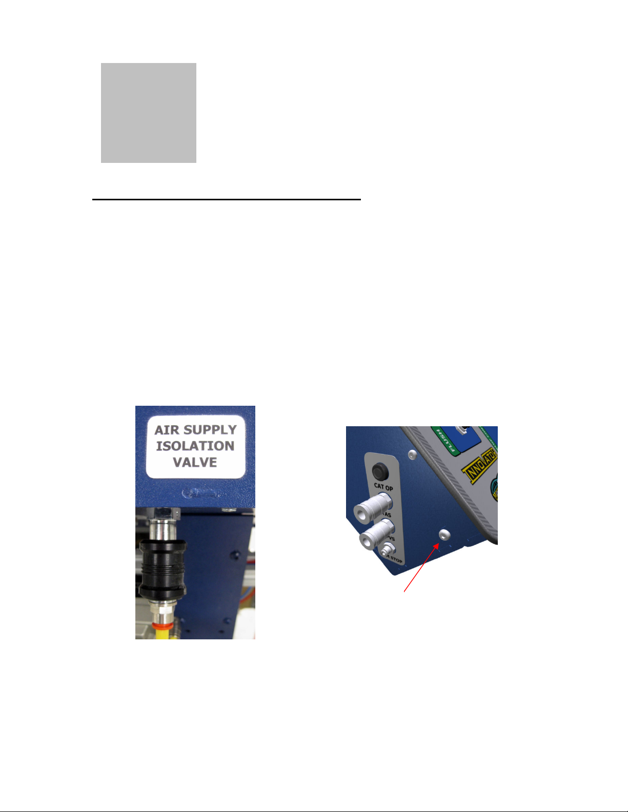
A sleeve valve, shown in figure 1.1 is provided on the rear of the enclosure so
that air may be isolated from the control box. Air should be removed from the
machine when it is not in use, by sliding the isolation valve sleeve away from the
control box.
Remove bolt from each side
to open lid.
Figure 1.1 – Air isolation valve Figure 1.2 – Lid securing bolts
In order to check that the control circuit air pressure is set correctly; open the lid
of the control box to access the regulator (with fitted gauge) by removing the two
lid securing bolts. A single bolt is positioned on each side of the control box; this
is illustrated in figure 1.2. The lid is hinged and can then be lifted upwards.
MAGNUM VENUS PLASTECH
17
Innovator Megaject Manual
Page 18

Locate the control circuit air pressure regulator (see section 5) and ensure that it
is adjusted to 6 bar (0.6 MPa) (ensure the slide valve is in the “ON” position). The
gauge is marked in Mega Pascal’s (MPa), where 1MPa = 10 bar = 145PSI.
Therefore the gauge should read 0.6.
NOTE: Exceeding the upper pressure or use of lubricated air could cause
permanent damage to the controls.
NOTE: When the isolation valve (sleeve valve) is in the off position, it is
possible that residual air pressures may still remain in the system.
Overview of controls
The Innovator control panel is shown in figure 2.1. Controls have been grouped
based upon function, to make the system as user friendly as possible.
Figure 2.1 – Innovator control panel
A brief overview of controls is as follows:
• Emergency Stop – Press this button in the event of an emergency to
place the system in a safe state. Twist and pull to release and allow
machine operation.
MAGNUM VENUS PLASTECH
18
Innovator Megaject Manual
Page 19

• Pump pressure
o Pressure gauge - This is the air pressure being supplied to the pump.
o Regulator – Adjust this to control the air pressure being supplied to
the pump and set the pump speed.
• Flush
o Press this button to operate the flush cycle.
• Start/Stop Controls
o Inject – Press to start the machine in inject mode.
o Recirculate – Press to start the machine in recirculation mode.
o Stop – Press to stop the machine in inject, recirculation or flush modes.
• Mould Pressure Guard
o Preset level gauge – Control signal air pressure being supplied to
Mould Pressure Guard (MPG) control.
o Regulator – Use this to adjust the MPG control signal air pressure.
• Stroke Count – The predetermining counter will count on each pump
stroke when the machine is in injection mode. The user can enter the
desired shot-count so that the machine stops automatically.
• RGA (Resin Gel Alarm) Indicator – If the RGA alarms, to alert the user
to the risk of resin curing in the machine, an audible alarm will sound and
this indicator will change from black to red.
Machine operations:
Before the system can be used the air isolation sleeve-valve must be moved to
the “ON” position and the E-Stop must be released. When air is initially supplied,
all controls should automatically reset to their non-operational state.
The various controls and operational modes are described in the following subsections.
Emergency Stop
When the E-Stop has been activated, the machine will enter a safe state. If the
machine is injecting, recirculating or flushing, the E-Stop is equivalent to pressing
the stop button.
NOTE: Residual pressures may remain in the system even though the E-Stop
has been activated and the air supply has been removed from the machine.
To de-activate the E-Stop, twist and pull to release.
MAGNUM VENUS PLASTECH
19
Innovator Megaject Manual
Page 20
Flush
Press the flush button to clean the injection head. The operator cannot initiate a
flush when the machine is in injection mode, therefore accidental flushing of the
system into a mould during an injection is not possible.
The flush system has an automatic timer function that will stop the flush cycle
automatically. The default duration of the flush is set between 30-60 seconds
during manufacture; however this can be adjusted by the user if required.
The flush cycle can be stopped at any time by pressing the stop button.
NOTE: Before the flush button is pressed, ensure that the outlet from the
mixing head is directed to a suitable waste container.
Mould Pressure Guard (MPG)
The machine features a Mould Pressure Guard (MPG), which is used to control
the maximum allowable pressure at the mixing head. This can be utilized to
provide line pressure control during an injection, or as a safety mechanism to
prevent the line pressure from exceeding the maximum working pressure of the
injection line to the mould.
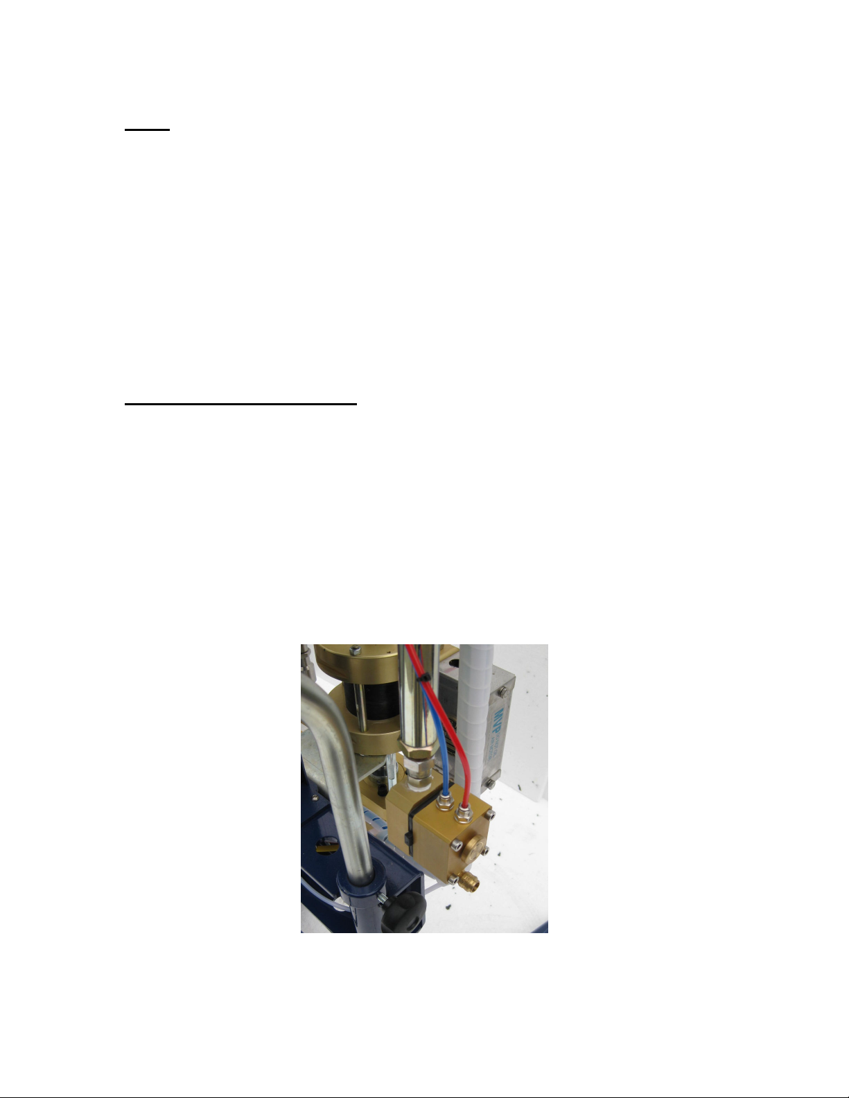
The MPG block is shown in figure 3.1. The blue air-line supplies air from the
MPG pressure regulator on the control panel. When fluid pressure at the injection
head exceeds the MPG preset level, shown on the MPG pressure gauge, the
internal diaphragm moves and leaks air from the red air line connected to the
control circuit. This causes the machine to slow and stop.
Figure 3.1 – Mould Pressure Guard (MPG) block
NOTE: The MPG control is active on both injection and recirculation modes. It
is correct to hear air leaking from the MPG block when the MPG is operational.
MAGNUM VENUS PLASTECH
20
Innovator Megaject Manual
Page 21

Catalyst over-pressure protection
The machine features catalyst over-pressure protection. In addition to the
industry standard inclusion of a pressure relief valve in the catalyst circuit, the
control circuit will detect the over-pressure condition and stop the pump from
running. In injection or recirculation modes, this is equivalent to pressing the stop
button.
For example, if during an injection the catalyst system is over-pressurized, the
injection will stop, the mixing head will return to the recirculate position and the
TAS signal will exhaust.
A visual indicator (see section 4) is provided on the side of the control box, which
will change from black to red in the event of a catalyst over-pressure condition.
To reset the over-pressure control circuit, the catalyst pressure must be relieved
and the reason for the condition must be remedied before the machine can be
operated in injection or recirculation modes.
Recirculation mode
Prior to and during operation in recirculation mode, use the pump pressure
regulator and gauge to suitably adjust the air pressure supply to the pump and
control the pump speed.
Press the recirculate button to start the machine, the pump will run and resin and
catalyst will be pumped around the system and returned to source.
Recirculation mode can not be entered when the machine is injecting.
To stop the machine, press the stop button.
NOTE: The MPG, PPVS and catalyst over-pressure controls are active
during recirculation.
Injection mode
Before an injection is started, ensure all external connections to the mould etc.
are correctly made. Also ensure that resin and catalyst lines are correctly primed
and that the required levels of materials are available. Ensure the level of fluid in
the flush tank is sufficient to clean the machine after the injection.
NOTE: When the system is initially primed with resin and catalyst, ensure
the machine is run in inject mode and resin is collected in a suitable
container from the mixing head and that air is purged etc. Once this has
been done, ensure the resin is correctly catalyzed by performing cup tests
prior to using the machine to inject a mould.
MAGNUM VENUS PLASTECH
21
Innovator Megaject Manual
Page 22
Prior to and during operation in injection mode, use the pump pressure regulator
and gauge to suitably adjust the air pressure supply to the pump and control the
pump speed.
Set the MPG set-pressure to the required pressure. Once the injection has
begun, the pump will stop running when the fluid pressure at the injection head
exceeds this setting. When the injection line pressure reduces below the MPG
set-pressure, the machine will continue to inject.
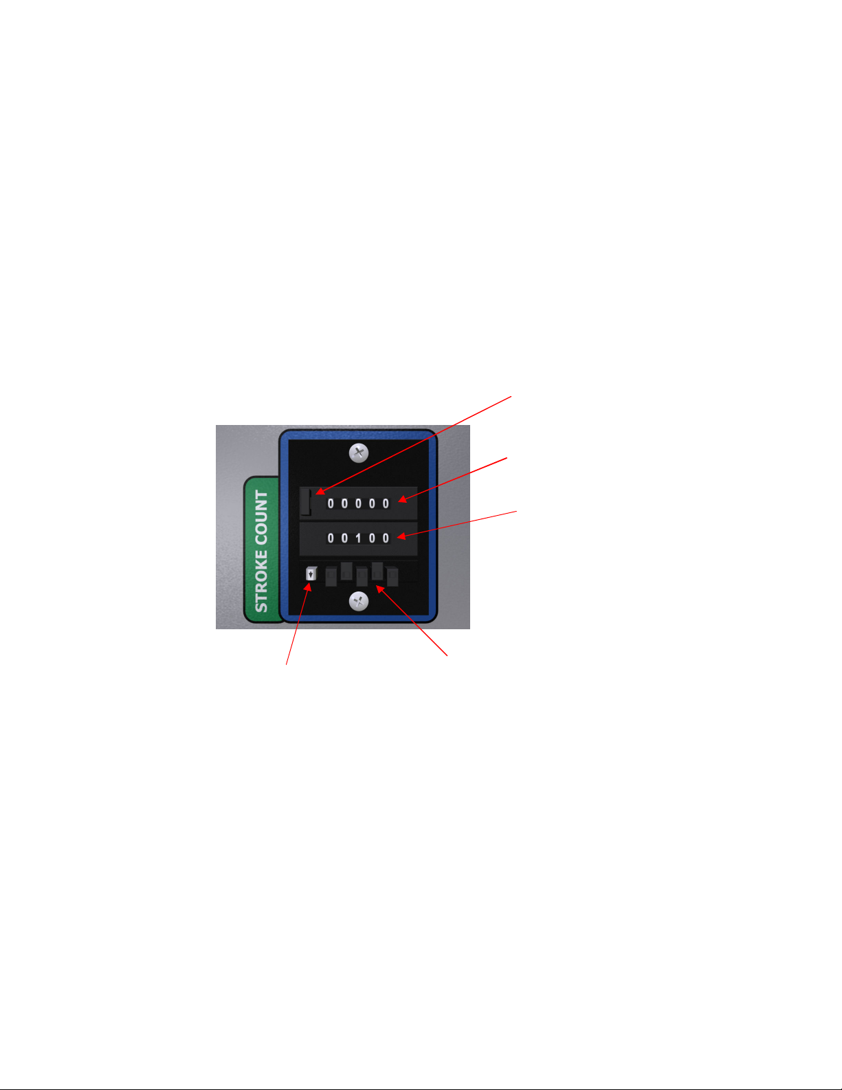
Adjust the predetermining counter to set the number of required pump strokes for
the injection. See figure 3.2 for an overview of the predetermining stroke counter.
To change the preset count, press and hold the white button with arrow decal
while pressing one of the black buttons under the preset count corresponding
with the digit to be modified.
Count reset button
Stroke count
Preset count
Press and hold when
adjusting preset count
Use these black buttons to
adjust preset count
Figure 3.2 – Predetermining counter
NOTE: The machine cannot be started in inject mode, if a previous injection
has stopped automatically when the shot count has been reached and the
stroke count has not been reset. Press the reset button on the predetermining
counter to reset the count and allow the machine to be started.
Press the inject button to start the machine in inject mode. The machine can not be
started in inject mode if it is operating in recirculation or flush modes. The injection
head will open, the TAS signal will pressurize and the pump will run. To stop the
machine and leave inject mode, press the stop button. If the predetermining counter
reaches the user set shot count, the machine will stop automatically.
If a PPVS sensor is being used the pump will stop when the mould pressure reaches
set-point. When the mould pressure drops to an acceptable level, the pump will run
once again.
MAGNUM VENUS PLASTECH
22
Innovator Megaject Manual
Page 23

RGA (Resin Gel Alarm)
The machine features a RGA (Resin Gel Alarm) system, designed to alert the
operator to the risk of catalyzed resin curing in the machine or mould during an
injection or prior the machine being flushed and cleaned.
When the inject button is pressed and the machine starts in injection mode, the
RGA becomes active. It monitors the time between pump strokes during an
injection and if the user-settable preset time is exceeded, an audible alarm will
sound and the visual RGA indicator on the control panel will change from black to
red.
The alarm is reset when the pump stroke changes direction in injection mode,
however in this case the RGA will continue to monitor the pump strokes and will
alarm again if the preset time between pump strokes is once again exceeded.
An example of this would be if the machine stalled during an injection due to a
higher than normal back-pressure in the injection line. The operator may increase
the injection pressure to make the pump stroke and therefore reset the alarm and
complete the injection.
The RGA is de-activated, so that it stops monitoring pump strokes and cancels
any active visual/audible alarms, by either flushing the machine or pressing the
RGA reset button.
The RGA reset button is hidden on the back of the control panel and can be
pressed by inserting a small screwdriver or equivalent through the hole marked
RGA reset. This is not intended to be used in normal operation and is provided
as a means to silence the alarm, if the pump cannot run and the machine cannot
be flushed.
A user configurable pneumatic timer, which can be adjusted between 20-300
seconds (0.3 – 5 minutes) is located in the control box. In addition, a factory set
timer of between 30-60 seconds is included in the RGA circuit to limit the
switching rate of the circuit. These two timers need to time-out in sequence in
order for the alarm to trigger. In practice if the mechanical timer is set to 5
minutes, if the duration of a pump stroke was to exceed around 5.5 – 6 minutes
during an injection, the alarm would trigger.
Guard Interlocks
If the machine is fitted with a slave arm guard that does not require a tool to open,
the guard will be fitted with an interlock to stop the pump running when it is opened.
In this case, if the guard is open, or not correctly closed, the machine will not
operate in injection or recirculation modes. Opening the guard while the pump is
operating will have the same effect as pressing the stop button.
MAGNUM VENUS PLASTECH
23
Innovator Megaject Manual
Page 24
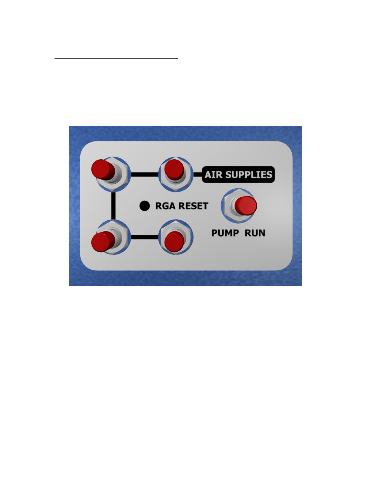
Control box user connections:
The rear of the control box, shown in figure 4.1, features the following connections:
• 4 air supplies – These can be used to supply machine options.
• Pump run signal – This signal is pressurized when the pump receives a
run signal. It can be used to control items such as resin heaters.
Figure 4.1 – Rear of control box
Signal connections are also supplied to the side of the control enclosure and are
illustrated in figure 4.2. The connections are as follows:
• Turbo Autosprue (TAS) – Use this to connect a TAS (or similar) valve to the
machine. The pilot signal will become pressurized when inject mode is active.
• PPVS Connector – Connect a pneumatic PV sensor (PPVS) here to
automatically control the system during an injection. The user can also
connect a “hold” or “pause” signal to the machine if required. When this
signal is leaked in injection mode, the machines pump will stop running.
When the signal is blocked, or no connection is made the pump will run.
• Stop – Connect a remote stop signal here. This function works similarly to
the stop button on the control panel and will stop the machine in inject or
recirculation modes when air is applied.
MAGNUM VENUS PLASTECH
24
Innovator Megaject Manual
Page 25

Catalyst over-pressure indicator
Turbo Autosprue (TAS)
PPVS or remote “pause” signal
Remote stop signal
Figure 4.2 – Side connections
The catalyst over-pressure indicator is also positioned on this connections panel.
It will turn red in the event of an over-pressure condition.
Control box configuration
The user can adjust the flush timer duration, the MPG response time and RGA
stroke timer and alarm volume. The procedures for doing this are described in
the following sub-sections. Use the air circuit for your machine controls to identify
the location of the components that require adjustment.
Many components in the control box are labeled to aid identification and
therefore locating items that may require adjustment should be relatively straight
forward with the aid of a circuit diagram.
The internals of a typical Innovator control box are shown in figures 5.1 & 5.2.
Some components have been marked for illustrative purposes; however it must
be emphasized that the appropriate air circuit should always be used as the
definitive reference.
MAGNUM VENUS PLASTECH
25
Innovator Megaject Manual
Page 26

RGA sub-assembly
PDC
Pump regulator sub-assembly
Figure 5.1 – Box lid internals
E-Stop sub-assembly
Valve plate sub-assembly
Control circuit pressure regulator
Figure 5.2 – Box base internals
NOTE: ALWAYS ENSURE THAT THE TUBE LOOMS THAT ARE RUN FROM THE
BASE OF THE BOX TO THE LID, ARE NOT KINKED AND POSITIONED
CORRECTLY TO THE SIDES OF THE ENCLOSURE WHEN THE LID IS CLOSED.
MAGNUM VENUS PLASTECH
26
Innovator Megaject Manual
Page 27

Flush timer adjustment
The flush timer duration can be increased or decreased by adjusting the flush
timer restrictor. This controls the rate of airflow out of the timer circuit reservoir,
and the speed that the pressure falls in order to actuate the automatic flush stop
valve.
To set the timer, simply adjust the restrictor and then time the flush cycle.
Continue this procedure until the desired flush time is obtained. Times of over 60
seconds are achievable with this circuit.
NOTE: If the restrictor is fully wound in, air flow will be blocked and the
timer will not operate.
MPG adjustment
The characteristics of the MPG control circuit can be modified by adjusting the
MPG restrictor. This component controls the rate at which air is supplied to the
pump speed control circuit. When the MPG, PPVS or catalyst over-pressure
devices leak air more air than can be supplied through this restrictor, the
pressure in the circuit falls and the pump stops.
When the circuit is once again sealed, the restrictor controls how quickly the
pressure builds within the circuit and therefore the time and speed in which the
pump restarts.
The slower the flow of air through the restrictor, the longer the pump will take to
restart.
NOTE: If this restrictor is fully wound-in, air flow will be blocked and the
pump will not start. Conversely, if too higher flow of air is supplied to the
circuit, safe and correct operation of the machine cannot be guaranteed.
The response of the pump can further be slowed if required, by the addition of an
air reservoir to the circuit. Contact MVP for further information.
MAGNUM VENUS PLASTECH
27
Innovator Megaject Manual
Page 28

RGA adjustment
The time between strokes permitted to pass before the RGA alarms and the
volume of the alarm whistle can be adjusted by the user.
The pneumatic RGA is located in the lid of the control box, behind the
predetermining counter. The mechanical timer is shown in figure 5.3. Turn the
knob to adjust the timer to the required time, between 20 – 300 seconds. The dial
shows seconds divided by 10, therefore to set the timer to 100 seconds, adjust
the dial to 10.
Figure 5.3 – RGA mechanical timer
The RGA alarm whistle volume can be changed by adjusting the flow controller
that is in line with the whistle.
MAGNUM VENUS PLASTECH
28
Innovator Megaject Manual
Page 29

SECTION
Innovator Megaject
OPERATING PROCEDURES
1. Pre-Start Check List for Innovator Megaject
2. First Time Start-Up for Innovator Megaject
3. Daily Start-Up for Innovator Megaject
4. Daily Shut Down for Innovator Megaject
The Check Lists are following:
MAGNUM VENUS PLASTECH
29
Innovator Megaject Manual
Page 30

PRE-START CHECKLIST
INNOVATOR MEGAJECT
ACTIVITIES MUST BE DONE IN THE SEQUENCE SHOWN, AND MUST BE TICKED
OFF AS COMPLETED.
ACTIVIT
ACTIVITY
Y NO.
Priority
1
2
3
4
5
6
7
8
9
10
11
12
Put on Respirator as specified for spray painting,
Protective Clothing, Eye Protection, and PVC Gloves
Have all Tools and materials available for pre-start checks.
Connect the 6mm air line to the to the air supply.
Slide the air valve on the back of the cabinet to OPEN position.
Twist & Pump E-Stop to allow machine operation
Check all catalyst & resin fitting to be sure they are tight
Fill pump packing nut 1/3 full with PAT-LS-OIL.
Fill the Catalyst Jug at least 1/2 full of catalyst.
Secure the Pick-up wand to the pump inlet
Place the Resin Pick-up wand in the resin supply container.
Place the end of the Resin Return Hose in the resin container.
Fill the Solvent Flush Tank 3/4 full.
Place the appropriate container under the Injection Head and
Test the Flush system by pressing the Flush Button.
THE UNIT IS NOW READY TO BE STARTED UP. GO TO – “FIRST TIME START-UP
INNOVATOR MEGAJECT”
ABNORMAL CONDITIONS OBSERVED AND CORRECTED
Abnormal Condition
aaaa when
corrected
OPERATORS NAME _____________________________DATE: _____________
SIGN OFF WHEN PRE-START CHECKS ARE COMPLETED: ____________________________
TICK WHEN
COMPLETED
MAGNUM VENUS PLASTECH
30
Innovator Megaject Manual
Page 31

FIRST TIME START-UP CHECK LIST
INNOVATOR MEGAJECT
ACTIVITIES MUST BE DONE IN THE SEQUENCE SHOWN, AND MUST BE TICKED
OFF AS COMPLETED. THIS SEQUENCE FOLLOWS ON FROM “PRE-START
CHECKLIST INNOVATOR MEGAJECT”
ACTIVIT
ACTIVITY
Y NO.
Priority
1
2
3
4
5
6
7
8
9
10
Put on Respirator as specified for spray painting, Protective
Clothing, Eye Protection, and PVC Gloves
Turn the pump regulator to zero
Adjust the catalyst percentage required with the slide arm Knob.
With all the material containers properly filled. Press the
Recirculation Button on the control panel.
Slowly increase the pump regulator so that the pump strokes
slowly and evenly.
Allow the pump to recirculate until the flow of Resin and Catalyst
back to there respective containers is free of bubbles.
Press the Stop button to take the unit out of recirculation mode
Test the catalyst and resin to the Injection head – Place a
suitable container under the injection head and press the Inject
button. After 4 or 5 strokes press the Stop button.
Check that the material properly cures
Properly dispose of the catalyst and resin.
Flush the Injection head as necessary into the appropriate
container.
ABNORMAL CONDITIONS OBSERVED AND CORRECTED
Abnormal Condition
OPERATORS NAME
________________________________
SIGN OFF WHEN START UP CHECKS ARE COMPLETED:
DATE:
____________
_______________________
TICK
WHEN
COMPLET
ED
aaaa when
corrected
MAGNUM VENUS PLASTECH
31
Innovator Megaject Manual
Page 32

ACTIVITIES MUST BE DONE IN THE SEQUENCE SHOWN, AND MUST BE TICKED OFF AS
COMPLETED. THIS SEQUENCE FOLLOWS ON FROM “FIRST TIME START-UP CHECKLIST”
ACTIVITY
NO.
Priority
1
2
3
4
5
6
7
8
9
10
11
12
13
14
15
DAILY START-UP
INNOVATOR MEGAJECT
ACTIVITY
Put on Respirator as specified for spray painting, Protective Clothing,
Eye Protection, and PVC Gloves
Check all hoses for damage.
Check all material supplies and fill or replace as needed.
Open main air supply slide valve on the back of the control box.
Press the recirculation button and allow the unit to recirculate for at least 20
strokes or until no bubbles are seen returning to the catalyst jug from the
recirculation tube.
Check that the catalyst percentage is set properly
Check resin pump pressure and adjust as necessary.
Check the MPG set pressure and adjust as necessary.
Set the desired number of counts o n the Counter Display.
Press the Stop button to take the unit out of recirculation mode.
It is always a good idea to do a gel test each morning and balance the fluid
pressures. So place the appropriate container under the injection head and
press the Inject button and pump 2 or 3 strokes. Then press the Stop button.
Press the Reset button on the Counter to reset the counter to zero.
Flush the injection head as necessary.
The unit is ready to inject a part – connect the injection hose to the injection
head and press the Inject button. If using a TAS (Turbo Autosprue), PPVS
or other options properly connect the control line to the control box.
When the injection is complete press the Reset button on the counter and
connect to the next part or flush.
Flush the injection head as necessary.
ABNORMAL CONDITIONS OBSERVED AND CORRECTED
Abnormal Condition
OPERATORS NAME
SIGN OFF WHEN START UP CHECKS ARE COMPLETED:
_______________________________
__________________________
DATE:
_____________
TICK WHEN
COMPLETED
aaaa when
corrected
MAGNUM VENUS PLASTECH
32
Innovator Megaject Manual
Page 33

DAILY SHUT DOWN CHECKLIST
INNOVATOR MEGAJECT
ACTIVITIES MUST BE DONE IN THE SEQUENCE SHOWN, AND MUST BE TICKED
OFF AS COMPLETED. THIS SEQUENCE FOLLOWS ON FROM “DAILY START UP
CHECKLIST”
ACTIVITY
NO.
Priority
1
2
3
4
5
Abnormal Condition
OPERATORS NAME
SIGN OFF WHEN SHUT DOWN CHECKS ARE COMPLETED:
MAGNUM VENUS PLASTECH
ACTIVITY
Put on Respirator as specified for spray painting, Protective
Clothing, Eye Protection, and PVC Gloves
Close TAS (Turbo Autosprue) or pinch injection hose to close the
mould
Press the Reset button on the Counter to reset the counter.
Flush the injection head and hose or TAS (Turbo Autosprue)
Disconnect the injection hose or TAS from the injection head.
Turn off the main air slide valve at the back of the unit.
ABNORMAL CONDITIONS OBSERVED AND CORRECTED
__________________________________
__________________________
33
Innovator Megaject Manual
DATE:
_______________
aaaa when
corrected
TICK WHEN
COMPLETED
Page 34

The page is left blank intentionally
MAGNUM VENUS PLASTECH
34
Innovator Megaject Manual
Page 35

SECTION
Innovator Megaject
FLUID SECTION MAINTENANCE
Innovator Megaject 3250: (8000)
The Innovator Megaject 3250 uses the Patriot 1-1/4” Fluid Section Assembly
(PAT-LS-12270-PE) – for detailed instructions for Repair & Maintenance of this
fluid section please reference the manual “Patriot 1-1/4” Fluid Section Manual
– PAT-LS-12270”.
Innovator Megaject 5000: (8001)
The Innovator Megaject 5000 uses the Patriot 1-3/4” Fluid Section Assembly
(PAT-LS-24050-PE) – for detailed instructions for Repair & Maintenance of this
fluid section please reference the manual “Patriot 1-3/4” Fluid Section Manual
– PAT-LS-24050”.
MAGNUM VENUS PLASTECH
35
Innovator Megaject Manual
Page 36

The page is left blank intentionally
MAGNUM VENUS PLASTECH
36
Innovator Megaject Manual
Page 37

SECTION
Innovator Megaject
CATALYST PUMP MAINTENANCE
Innovator Megaject 3250: (8000)
This Innovator Megaject uses the Patriot Catalyst Pump Assembly (PAT-CP-
0550) – for detailed instructions for Repair & Maintenance of this Catalyst Pump
please reference the manual “Patriot Catalyst Pump Manual PAT-CP-0550”.
SLIDE DRIVE STICKERS:
2%2.5% 1.5% 1%
FLIUD SECTION PAT-LS-12270 and PAT-CP-0550
.75%
PAT-RS-12 27-055
Innovator Megaject 5000: (8001)
This Innovator Megaject uses the Patriot Catalyst Pump Assembly (PAT-CP-
0980) – for detailed instructions for Repair & Maintenance of this Catalyst Pump
please reference the manual “Patriot Catalyst Pump Manual PAT-CP-0980”.
SLIDE DRIVE STICKERS:
FLIUD SECTION PAT-LS-24050 and PAT-CP-0980
MAGNUM VENUS PLASTECH
2%2.25% 1.5% 1%
37
.75%
Innovator Megaject Manual
PAT-RS-2405-098
Page 38

The page is left blank intentionally
MAGNUM VENUS PLASTECH
38
Innovator Megaject Manual
Page 39

SECTION
Innovator Megaject
POWERHEAD MAINTENANCE
Innovator Megaject 3250: (8000)
This Innovator Megaject uses the Patriot 3-1/4” Powerhead Assembly (PAT-PH-
3250) – for detailed instructions for Repair & Maintenance of this fluid section
please reference the manual “Patriot Powerhead Manual PAT-PH-3250”.
Innovator Megaject 5000: (8001)
This Innovator Megaject uses the Patriot 5” Powerhead Assembly (PAT-PH-5000)
– for detailed instructions for Repair & Maintenance of this fluid section please
reference the manual “Patriot Powerhead Manual PAT-PH-5000”.
MAGNUM VENUS PLASTECH
39
Innovator Megaject Manual
Page 40

The page is left blank intentionally
MAGNUM VENUS PLASTECH
40
Innovator Megaject Manual
Page 41

SECTION
Innovator Megaject
INJECTION HEAD & MIXER ASSY.
Following in this section are the instructions for the items listed below:
1. Auto Head Assembly
2. Catalyst Auto Valve Assembly - CAV
3. Resin Auto Valve Assembly - RAV
4. Head Mixer & Mould Pressure Guard (MPG)
5. Automatic Flush Valve Assembly
MAGNUM VENUS PLASTECH
41
Innovator Megaject Manual
Page 42

1. Auto Head Assembly
MAGNUM VENUS PLASTECH
42
Innovator Megaject Manual
Page 43

2. Catalyst Auto Valve Assembly – CAV
Servicing notes:
The catalyst auto valve needs little servicing as all components are suitable for
both MEKP and recommended AAP catalysts
The movement of the spool as indicated from the aluminium air cylinder end
should be between 4 and 5 mm. Any less or greater can cause Catalyst to flow
incorrectly so ensure this movement is observed to be correct by measurement
using callipers after service and before using the machine in production.
Take care not to damage or scratch the spool internal body 6369 when O ring 3316
needs replacing.
The valve should only need servicing if air or catalyst is noted to weep from
between the air cylinder 6078 and Stainless steel body 6067. In this case the O
ring 3316 should be renewed.
MAGNUM VENUS PLASTECH
43
Innovator Megaject Manual
Page 44

If catalyst appears to weep back to the catalyst bottle during injection mode then
B. Recirculation
the internal spool O rings (6004) need replacing.
If catalyst is observed to weep from the injection nozzle during recirculation mode
then the small front O ring (6079) needs replacing.
A. Injection
Illustration of Catalyst
Auto valve cross
section showing
catalyst flow and
correct position of air
actuator for
A. injection flow
And
B. recirculation flow
MAGNUM VENUS PLASTECH
44
Innovator Megaject Manual
Page 45

3. Auto Resin Valve Assembly - RAV
RAV – Instructions for use and Maintenance:
1. Use air signal on 4mm fitting 6080 to open valve, valve closes when signal
is removed
2. To replace the Main Seal (5873), remove Hex Head Screw (5832), Seal
(5837) and Washer (6059). Replace Seal (5837) with the recess against
the screw head. Use a small amount of removable thread lock compound
on the 5mm of exposed threads nest to Seal and Washer only. Do not over
tighten Hex Head Screw.
Note:
• Seal (5837) would normally be replaced by removing Nose Block
(5852 first. However it can be accessed / replaced by unscrewing the
Screw (5832) without removing the Nose Block (5852).
• If the shaft turns whilst removing Screw apply signal air pressure to
open connector (6080) this aids locking the shaft against rotation.
• It is essential that screw is not over tightened and only a small
amount of locking compound is used
• After renewing Seal ensure correct operation and sealing efficiency
between open and closed positions before production use.
3. To replace Shaft Seal (6004), remove Main Seal (5837). Disconnect Signal
Pressure. Unscrew to remove Cylinder Top (6167). Caution the top is
under spring pressure. Remove Spring (5825) and Limiter (5835). Pull
Piston Shaft (5827) upwards. Either cut Seals off Shaft without scratching
grooves in shaft and replace or replace Shaft (5828) complete with Seals
fitted. Shaft (5828 may be unscrewed form Shaft (5827) by firmly gripping
both close to piston (5830). Reassemble using a small amount of thread
lock compound on threads and PTFE sealer paste on Shaft end next to
piston base hole (5830). Do not grip and turn shaft beneath O-ring seal
grooves.
Caution Note. For safety reasons - Always ensure that the Resin Auto
valve above is locked into the head top position with the two securing lock
M5 screws 4081
MAGNUM VENUS PLASTECH
45
Innovator Megaject Manual
Page 46

MAGNUM VENUS PLASTECH
46
Innovator Megaject Manual
Page 47

4. Head Mixer and Mould Pressure Guard (MPG)
MAGNUM VENUS PLASTECH
47
Innovator Megaject Manual
Page 48

5. Automatic Flush Valve Assembly 58742-PLAS
The Automatic Solvent Flush Valve may be serviced. NOTE, however the
important use of thread lock compound between parts 3 and 8. These two parts
need to be disassembled if the main solvent seal 19 needs renewing so ensure
that a thread lock compound is used when reassembling.
MAGNUM VENUS PLASTECH
48
Innovator Megaject Manual
Page 49

Yellow outlet tube connects
Inlet air tube loops up and
SECTION
Innovator Megaject
SP4 SOLVENT PUMP ASSEMBLY
SP4 Solvent Pump Assembly – The SP4 performs a 200cc solvent purge
followed by an air purge to thoroughly clean and purge the injection head and
mixer. It is contained in a 3 gallon Stainless Steel flush tank. During the flush
cycle only the SP4 solvent pump will be pressurized to force out the solvent
contained inside and then purges with air for the reminder of the flush cycle.
The SP4 is activated by pressing the Flush button on the control panel and will
operate for 30 to 60 seconds. The duration of the flush / purge cycle can be
adjusted as previously noted in the Section 2 – Control Box configuration.
Connecting the SP4 – Connect the yellow outlet tube from the outlet side of the
solvent pump through the outlet fitting to the flush neck on the flush valve of the
injection gun.
Connect the red 4mm tube to the fitting on the inlet side of the quick exhaust.
Connect the 1/4" pump inlet air tube to the other side of the inlet quick exhaust.
down through the inlet fitting
and connects to the inlet of
the solvent pump
1/4” Pump inlet air tube
from injection gun flush
valve to the outlet of the
SP4 solvent pump.
MAGNUM VENUS PLASTECH
49
Red 4mm flush signal line
Flush Tank
Innovator Megaject Manual
Page 50

On the inside of the flush tank the there are two (2) connections to the flush pump.
• The pump inlet air tube connects to the inlet side of the SP4 solvent pump
through the inlet fitting.
• The Yellow flush tube from the injection gun / mix head extends down
through the outlet side fitting and connects to the outlet of the solvent pump.
Note: it is important that the solvent level in the tank be at no less then 1/3
full or so that there is 25mm (1”) of solvent above the SP4 solvent pump.
This will allow the SP4 solvent pump to properly refill with solvent after
each use.
Maintenance – The SP4 Solvent Pump is basically maintenance free however it
might be necessary to replace the O-ring (0464) on the Pump Foot Valve (4481).
It is important to keep the inside of the flush tank clean and free of dirt, debris
and glass fiber as these can prevent the Pump Foot valve from sealing properly.
MAGNUM VENUS PLASTECH
50
Innovator Megaject Manual
Page 51

SECTION
Innovator Megaject
PARTS DRAWINGS
1: Patriot Fluid Section Parts Drawings:
PAT-LS-12270-PE MEGAJECT INNOVATOR FLUID SECTION ASSY
PAT-SD-3100 PATRIOT SLAVE DRIVE ASSEMBLY
PAT-LS-12270-R-SK SEAL KIT – RTM (SSB)
2: Patriot Catalyst Pump – PAT-CP-0550 Drawings:
PAT-CP-0550 CATALYST PUMP ASSEMBLY
PAT-CP-0550-SK SEAL KIT – PATRIOT CATALYST PUMP
3: Patriot Powerhead Parts Drawings:
PAT-PH-3250 3-1/4” PATRIOT POWERHEAD 2” STROKE ASSEMBLY
PAT-PH-3250-SK SEAL KIT – 3-1/4” PATRIOT POWERHEAD
PAT-PH-5000 5” PATRIOT POWERHEAD 2” STROKE ASSEMBLY
PAT-PH-5000-SK SEAL KIT – 5” PATRIOT POWERHEAD
4: SP4 Solvent Pump Parts Drawings:
82006_01 SP4 FLUSH TANK OUTLET ASSEMBLY
82004_01 SP4 PUMP ASSEMBLY
82005_01 SP4 FLUSH TANK INLET ASSEMBLY
82007_01 SP4 FLUSH TANK ASSEMBLY
83002_02 MEGAJECT INNOVATOR AIR CIRCUIT
5: Injection Head Parts Drawings:
82009_01 MPG VALVE ASSEMBLY
22021_04 CATALYST OVERPRESSURE VALVE ASSEMBLY
MAGNUM VENUS PLASTECH
51
Innovator Megaject Manual
Page 52

MAGNUM VENUS PLASTECH
52
Innovator Megaject Manual
Page 53

MAGNUM VENUS PLASTECH
53
Innovator Megaject Manual
Page 54

MAGNUM VENUS PLASTECH
54
Innovator Megaject Manual
Page 55

MAGNUM VENUS PLASTECH
55
Innovator Megaject Manual
Page 56

PAT-LS-12270-R-SK PATRIOT SEAL KIT - RTM
MAGNUM VENUS PLASTECH
56
Innovator Megaject Manual
Page 57

MAGNUM VENUS PLASTECH
57
Innovator Megaject Manual
Page 58

MAGNUM VENUS PLASTECH
58
Innovator Megaject Manual
Page 59

MAGNUM VENUS PLASTECH
59
Innovator Megaject Manual
Page 60

MAGNUM VENUS PLASTECH
60
Innovator Megaject Manual
Page 61

MAGNUM VENUS PLASTECH
61
Innovator Megaject Manual
Page 62

MAGNUM VENUS PLASTECH
62
Innovator Megaject Manual
Page 63

MAGNUM VENUS PLASTECH
63
Innovator Megaject Manual
Page 64

MAGNUM VENUS PLASTECH
64
Innovator Megaject Manual
Page 65

MAGNUM VENUS PLASTECH
65
Innovator Megaject Manual
Page 66

MAGNUM VENUS PLASTECH
66
Innovator Megaject Manual
Page 67

MAGNUM VENUS PLASTECH
67
Innovator Megaject Manual
Page 68

MAGNUM VENUS PLASTECH
68
Innovator Megaject Manual
Page 69

Page 70

70
Innovator Megaject Manual
MAGNUM VENUS PLASTECH
Page 71

71
Innovator Megaject Manual
MAGNUM VENUS PLASTECH
Page 72

72
Innovator Megaject Manual
MAGNUM VENUS PLASTECH
Page 73

73
Innovator Megaject Manual
MAGNUM VENUS PLASTECH
Page 74

74
Innovator Megaject Manual
MAGNUM VENUS PLASTECH
Page 75

SECTION
Innovator Megaject
REVISION INFORMATION:
REV: 05/2010 Document was created – not formally released but
forwarded to several people.
Rev: 05/2010A Updated the Controls Section – Added SP4 Solvent
Pump information. Added Component Manual
information to the back cover.
Rev: 08/2010 Added SP4 Solvent Pump information & drawings.
Rev: 10/2010 Updated SP4 Solvent Pump information &
drawings. Changed Pump to PAT-LS-12270-PE
Rev: 02/2011 Added the Air Circuit (83002_02), MPG Valve
(82009_01) and Catalyst Overpressure (22021_04)
to the drawing section. Included the 5” Powerhead
option for the 15:1 Units.
Rev: 05/2011 Updated the manual to include the both version of
the Innovator Megaject units (Innovator Megaject
3250 (8000) & Innovator Megaject 5000 (8001)).
The manual now includes the PAT-LS-24050 fluid
section and PAT-CP-0980 catalyst pump options.
MAGNUM VENUS PLASTECH
75
Innovator Megaject Manual
Page 76

The page is left blank intentionally
MAGNUM VENUS PLASTECH
76
Innovator Megaject Manual
Page 77

MAGNUM VENUS PLASTECH
CORPORATE HEADQUARTERS and MANUFACTURING
5148 113th Ave. N. *Clearwater, FL 33760 * Tel 727-573-2955 * Fax 727-571-3636
WEST COAST MANUFACTURING
1862 Ives Ave. * Kent, WA 98032 * Tel 253-854-2660 * Fax 253-854-1666
MVP Plastech UK
Chilsworthy Beam, Gunnislake, Cornwall, PL18 9AT UK, * Tel:+44 (0) 1822 832621
Fax: +44 (0) 1822 833999
www.mvpind.com
Included with this operations manual are the following component manuals:
MAGAJECT INJECTION HEAD
Innovator Megaject 3250: (8000)
PATRIOT POWERHEAD MANUAL PAT-PH-3250
PATRIOT 1-1/4” FLUID SECTION MANUAL – PAT-LS-12270
PATRIOT CATALYST PUMP MANUAL PAT-CP-0550
Innovator Megaject 5000: (8001)
PATRIOT POWERHEAD MANUAL PAT-PH-5000
PATRIOT 1-3/4” FLUID SECTION MANUAL – PAT-LS-24050
PATRIOT CATALYST PUMP MANUAL PAT-CP-0980
Rev: 05/2011
MAGNUM VENUS PLASTECH
77
Innovator Megaject Manual
 Loading...