

Page 1
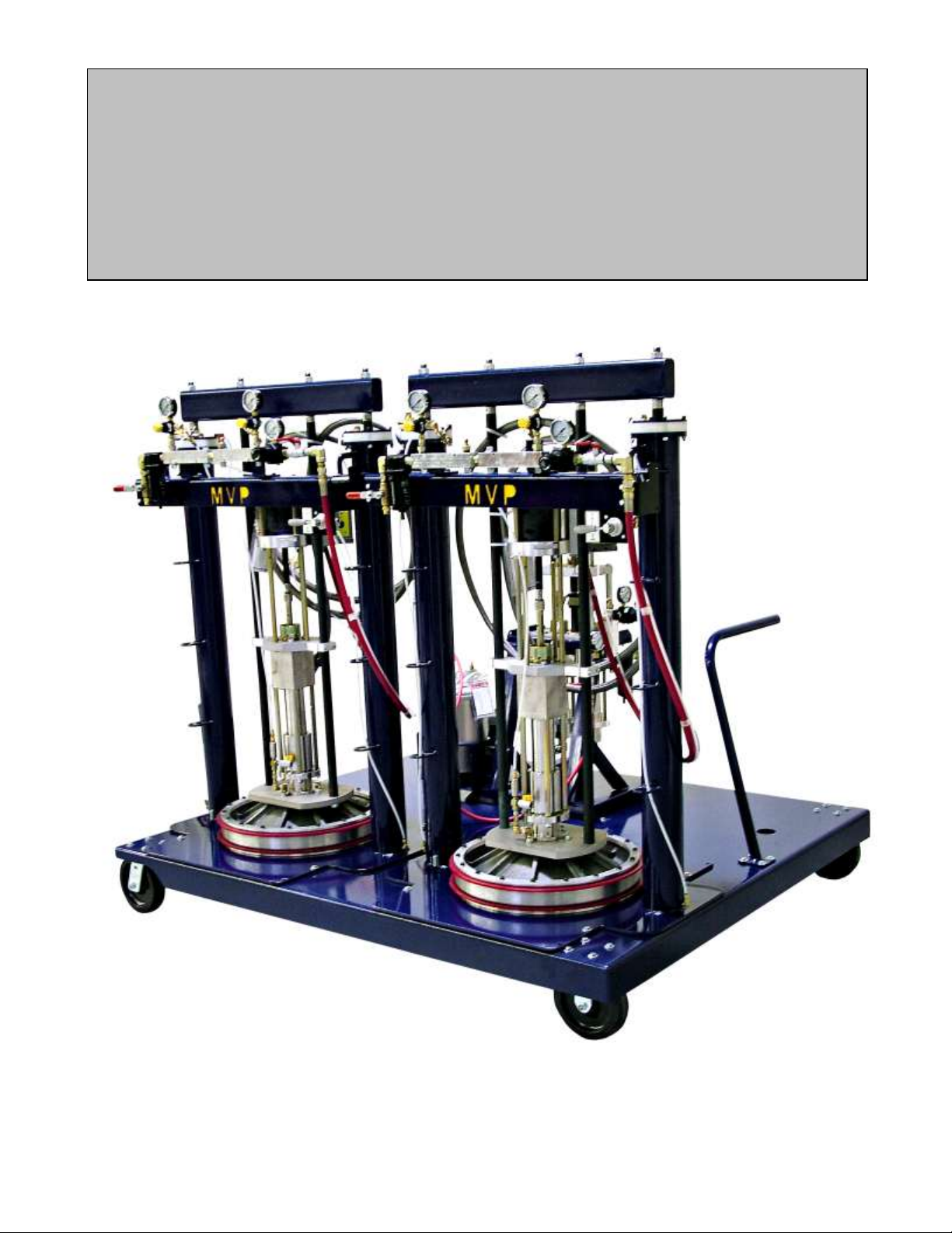
ULTRABOND
Methacrylate Adhesive Dispensing unit
IMP-DUO-54646
Start-Up Instructions
MAGNUM VENUS PLASTECH
UltraBond Start-Up Instructions Rev. 5/07
Page 2

Page 3

START-UP INSTRUCTIONS
1. Attach main air supply to the air manifold on both systems.
NOTE: The regulators marked pump, air lift and ram extraction should be set at zero on all
systems.
2. On the Duo Link unit fill solvent tank with solvent. Turn the air supply to the flush system to
60psi (4 bar). Check for solvent leaks and test flush system by flushing the dispensing head.
3. Located on the Ram units check and adjust the Ram Lower Limit. By adjusting the APD-1011
bracket the pump piston stop height can be adjusted in the drum. (see drawings below)
PRIMING ADHESIVE TO GUN
4. Move the rotary valve handle (06275) to the up position.
NOTE: Do not install static mixer tube to gun at this time.
5. Open the ball valve located off of the regulator and gauge marked airlift cylinder. To raise the
ram and barrel piston, slowly increase air regulator (marked AIRLIFT) to 15 to 20 psi.
6. While the barrel piston is going up, check that no hoses are kinking.
7. Once ram is to maximum up position, tape the Piston Boot (60531-1) the round piece of
plastic (use plastic boot as a template to make more before installing) to the top of the barrel
piston. Make sure that the round hole in the center of the plastic piston boot is centered with
the opening at the bottom of the barrel piston.
NOTE: If the 55-gallon drum has a plastic liner it is helpful to prevent the liner from being
pushed down into the drum. Use the ring from the drum top to hold the liner in place or
tape the liner to the outside of the drum. Inspect the drum for dents and damage, using
a dented or damaged drum can damage the piston seals and cause leaking.
8. Slide 55-gallon drum of adhesive onto the unit and center drum to the barrel piston.
9. Open ball valve (06276)) located at the top of the barrel piston; this will allow air trapped
between the barrel piston and the putty to escape.
10. To lower barrel piston down into the drum, push rotary valve (06275) handle to down position.
11. Once barrel piston has started into adhesive drum, slowly increase airlift regulator pressure 80
to 100 psi.
NOTE: Allow time for air to be pushed out of the ball valve (06276) at the top of the barrel
piston.
12. Once barrel piston has come to a complete stop, close ball valve (06276) at the top of the
barrel piston.
13. Remove the night cap or mixer assembly from the front of the dispensing block.
14. Pull the manual gun handle back to the open position, and leave in the open position.
Page 4

15. At the air manifold, slowly increase regulator marked pump. Do this for both of the ram
adhesive pumps.
16. Adjust pump regulators as needed to maintain a slow uniform movement of the adhesive
pumps.
NOTE: It may take more pressure for one drum of material than another as the viscosity may
be different.
17. At the Duo Link unit slowly increase the pump pressure as needed to maintain a slow uniform
movement of the Duo Link adhesive pumps.
18. Allow units to run until a steady flow of adhesive material is being dispensed out both sides of
the dispensing block with no air pockets.
19. Push the dispensing head handle to the close position.
20. Flush both sides of the dispensing head.
21. To build fluid pressure, push the priming button (09188) located on the Duo Link air manifold
that is labeled prime.
22. While pushing the priming button in, slowly increase the pump regulator, 80 to 90 psi for
maximum flow rates. Once pump has come to a stop, release priming button.
NOTE: For best results perform a ratio check at the dispensing head. The pump pressure on
the ram adhesive units should be kept as low as possible to prevent over riding the
inlet balls in the Duo Link unit. The pressure may need to be adjusted differently on two
ram units because of viscosity differences and to reach a 1:1 ratio.
NOTE: Apply a small amount of red grease on the dispensing head threads before installing
mix tube to gun.
23. Install mixing tube (05260) onto gun head, making sure there is a seal (02029-1) between the
mix housing and the adapter union fitting (54861-1). The static mixers (05271) have a notch
on one end that inner lock the four mixers together.
NOTE: The notch should face up when installing into the mix tube (05260).
Page 5

Daily - Startup & Shut-Down UltraBond Adhesive Unit
DAILY STARTUP
1. Check and refill all components and materials.
2. On the Duo Link unit close the relief valve on the flush tank lid.
3. On the ram adhesive pumps open the lockout ball valve (7702-2-2) to pressure up the system.
4. On the ram adhesive pumps slowly open the air ball valve (09350) to the pump.
5 On the Duo Link unit open the main air supply to pressure up the system.
6. On the Duo Link unit push and hold the priming button while slowly opening the air ball valve
to the pump.
7. Remove the night cap plug (HOD-1002).
8. Apply a small amount of red grease (7607-2-1) to the threads of the dispensing head.
8. Reassemble and attach static mixer assembly.
9. Check flush system for proper operation.
DAILY SHUT-DOWN
1. Drain water trap filter (06989) daily.
2. Thoroughly flush the dispensing head.
3. Remove static mixer tube and push the four static mixers (05271) out of tube.
4. Thoroughly clean mixers and mix tube with solvent.
5. On the ram adhesive units close the air ball valve (09350) to the pump.
6. On the ram adhesive units close the lockout ball valve (7702-2-2) to relieve air pressure from
the system.
7. On the Duo Link unit close the air ball valve to the pump
8. On the Duo Link unit close the lockout ball valve (7702-2-2) to relieve air pressure from the
system
9. Lift the relief valve on the flush tank lid to release flush tank pressure.
10. Install night cap plug (HOD-1002) to the front of the dispensing head.
NOTE: Do not leave barrel piston in 55-gallon drum if the system will be idle for more then two
weeks.
Page 6

Parts Drawing Section:
APD-1010 Assembly – Frame Work Ram Cylinder
APD-1000-ADH Frame Work Ram Cylinder assembly
Page 7

MAGNUM VENUS PRODUCTS
ASSY - FRAME WORK RAM CYL.
APD-1010
REV - 09/08/05 BT2
EXISTING RAM
POST
3
1
2
4
5
6
7
7
8
Page 8

ASSY - FRAME WORK RAM CYL. APD-1010
ITEM
PART NO. QTY
DESCRIPTION
PARTS LIST
6
09068 1
VALVE BRACKET
3
09343 1
BALL OPERATOR
2
09321 1
NORMALLY OPEN VALVE
1
APD-1009
1
MOUNT BRACKET
7
MPH-2534
2
POLY ELBOW
5
F-CS-832-04
2
CAP SCREW
4
F-CS-05C-20 2
CAP SCREW
8
APD-1011 1 SHAFT COLLAR
Page 9

5
43
36
21
39
44
41
41
33
RESIN PUMP (REF)
46
59
60
616263
6163 62
58
57
REV. A= ITEM 8 WAS 02805-16, ITEM 46 WAS 00404, DELETED ITEMS 42 (PF-HP-04) AND ITEM 51 (F-CS-05C-20) 4/23/07 JEM
48
49
50
53
47
52
54
38
55
56
4
6
39
31
12
39
36
31
31
43
45
40
28
29
26
29
27
7
30
1
2
39
24
35
38
5
2
23
22
3
MAGNUM VENUS PRODUCTS
ASSY - FRAME WORK RAM CYL.
- 09/07/05 BT2REV.
20
11
DETAIL
& RAM EXTRACTION
BLEED OFF VALVE
APD-1000-ADH
BARREL PISTON (REF)
8
32
2011
16
18
17
38
5
14
13
43
Page 10

2
O-B-342 4
O-RING
3
02005
2
CYLINDER ROD SEAL
4
02007 2
CYLINDER ROD WIPER
5
02576 10 WASHER
6
02668-18
8
SOCKET HEAD CAP SCREW
7
02685-24
18
SHOULDER BOLT
8
F-PH-832-28 2
PAN HEAD SCREW
11
06270
2
BARREL HOD DOWN KNOB
12
06271 2 CYLINDER ROD CLAMP COLLAR
13
06274 1
CHECK VALVE
14
CM-1005
1
BALL VALVE
16
PF-SW-04-04J-SS
1
SWIVEL ADAPTER
17
PF-HN-04-04J-SS 1
MALE CONNECTOR
18
PF-PT-04MMF-SS
1
FEMALE RUN TEE
20
APD-1005 2 BARREL CLAMP
21
APD-1003 2
SUPPORT ROD
22
60514-1
2
SUPPORT RING
23
60515-3 2
CYLINDER CAP
24
60517-1
2
LIFT CYLINDER PISTON
26
60519-11
1
BARREL PISTON
27
60519-13 1 TOP RING - BARREL PISTON
28
60519-5 1
BOTTOM RING - BARREL PISTON
29
60520-1
2
SEAL - BARREL PISTON
30
60521-1 18
SPACER - BARREL PISTON
31
APD-1004
2
CYLINDER ROD
32
APD-1001
1
FRAMEWORK LIFT CYLINDER
33
60533-1 1
SUPPORT PANEL
35
60539-1 2
MOUNT BRACKET - MANIFOLD
36
APD-1002
1
WELDMENT - SUPPORT BAR
38
F-HB-04C-12 8
HEX CAP SCREW
39
7201-1-12
8
HEX NUT
40
F-HN-832
2
HEX NUT
43
7701-6-2 5
POLY ELBOW
44
PF-HN-04TS-04 3
POLY CONNECTOR
45
06275
1
ROTARY VALVE
46
MPM-2568
1
BREATHER VENT
47
APD-1009
1
MOUNT BRACKET
48
APD-1011 1
SHAFT COLLAR
49
09321 1
NORMALLY OPEN VALVE
50
09343 1
BALL OPERATOR
52
F-CS-832-04
2
CAP SCREW
53
09068
1
VALVE BRACKET
54
MPH-2534 2
POLY ELBOW
55
60534-1 1
SUPPORT HOOK
58
PF-SE-04-SS
1
STREET ELBOW
59
APD-1007
1
MOUNTING BRACKET
60
6101-4-01
1
FLUSH TANK BRACKET
61
F-HB-06C-16 4
HEX BOLT
62
F-SW-06 4
LOCK WASHER
63
F-HN-06C 4 HEX NUT
57
MPM-2052-1 20 FT. TUBE
41
F-HN-04C-12 8
HEX NUT
56
APD-1010 1
RAM LIMIT VALVE ASSY
ITEM
PART NO. QTY
DESCRIPTION
OPTIONAL PARTS & ASSEMBLIES
ASSY - FRAME WORK RAM CYL. APD-1000-ADH
1
F-LN-05C
8
LOCK NUT
ITEM
PART NO. QTY
DESCRIPTION
PARTS LIST
Page 11

Corporate Headquarters/Manufacturing
5148 113th Ave.
Clearwater, FL 33760 USA
Ph: (727) 573-2955
Fax: (727) 571-3636
MVP Technology Center
1862 Ives Ave.
Kent, WA 98032 USA
Ph: (253) 854-2660
Fax: (253) 854-1666
E-mail: info@mvpind.com · Web: www.mvpind.com
MAGNUM VENUS PLASTECH
 Loading...