

Page 1
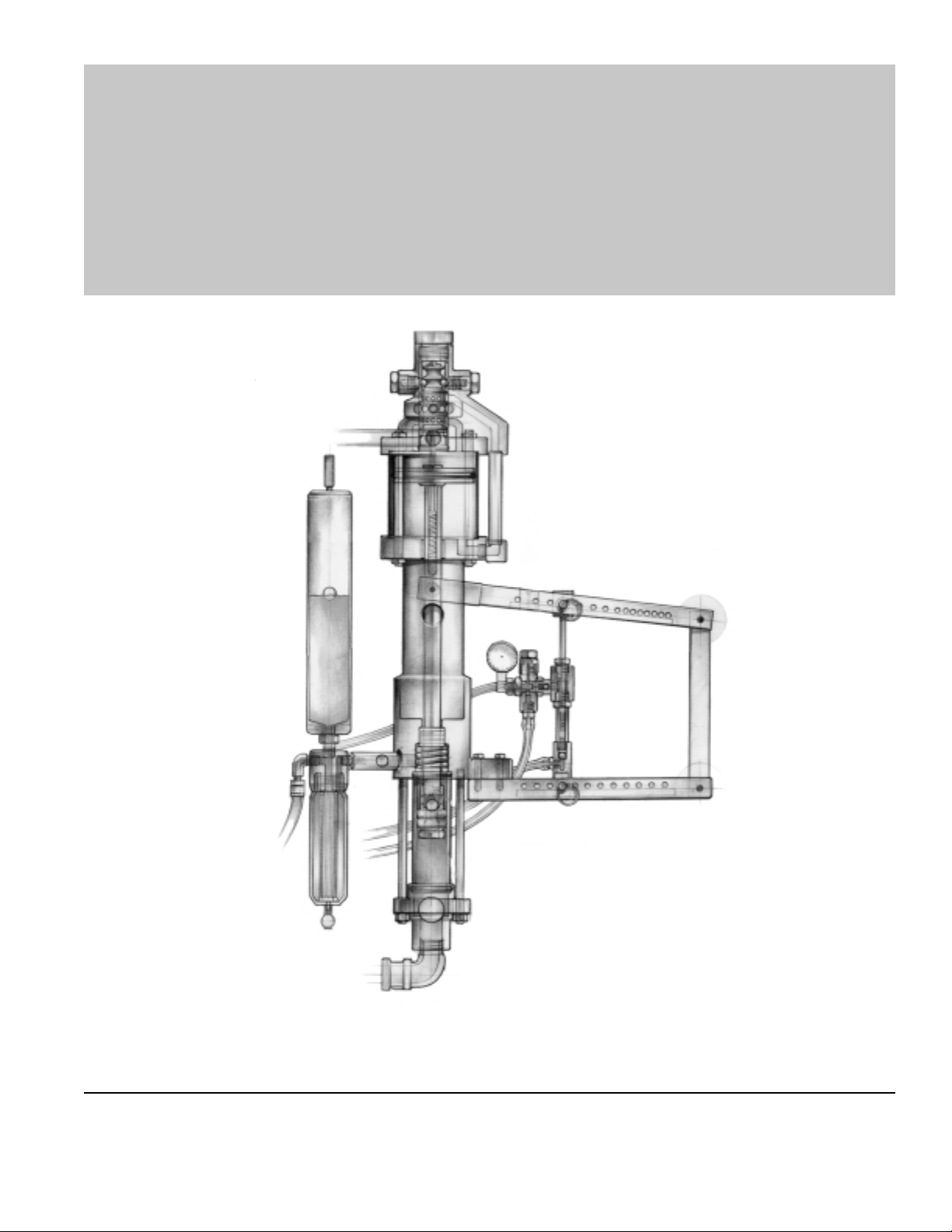
SUPERCHARGED
H.I.S.™
MAGNUM VENUS PRODUCTS
Operation Manual
P/N: 90084-1
SUPERCHARGED H.I.S.™
Revision 04.09.01
Page 2

Corporate HQ/Mfg. MVP T echnology Center
5148 1 13th A ve. 1862 Ives A ve.
Clearwater, FL 33760 Kent, WA 98032
Tel: (727) 573-2955 Tel: (253) 854-2660
Fax: (727) 571-3636 Fax: (253) 854-1666
SUPERCHARGED H.I.S.™
E-mail: info@mvpind.com · Web: www.mvpind.com
© 2001 Magnum Venus Product s Manual Part No: 90084-1
Page 3

H.I.S. SUPERCHARGED System
Operations Manual
T able of Contents
CHAPTER 1
Quick List
CHAPTER 2
Start-up Procedure
CHAPTER 3
Priming the Catalyst Pump
Priming the Resin Pump
CHAPTER 4
Creating a Proper Spray Pattern
CHAPTER 5
Shut-down Procedure
CHAPTER 6
Removing Materials from the System
CHAPTER 7
Reassembly of Resin Accumulator and Resin Filter
APPENDIX
Drawings
SUPERCHARGED H.I.S.™
Page 4

Chapter
11
1
11
H.I.S. SUPERCHARGED
1. Check all fittings for proper connection.
2. Fill solvent tank.
3. Prime the catalyst pump.
4. Prime the resin pump.
Quick List
5. Relieve fluid pressure from the unit by opening the ball valve under
the resin filter.
6. Insert the charging hose onto the resin accumulator.
7. Close the ball valve under the resin filter.
8. Adjust for proper spray pattern.
NOTE: These instructions include resin and catalyst pressurization procedures.
To avoid equipment malfunction or possible injury, please follow these
instructions. If you have any questions, please contact our Technical Service
Department at 800-448-6035.
SUPERCHARGED H.I.S.™
Page 5
Start-up procedure
The following steps should be followed when the unit is
new, has been recently repaired or has no material in the
system.
1. Check all fittings for proper connection.
Chapter
NOTE
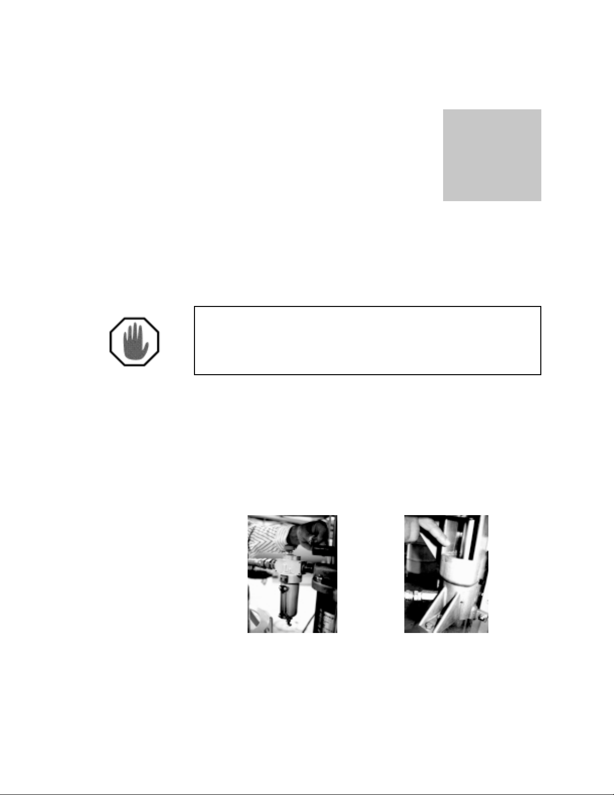
2. Fill resin pump power head oiler to designated mark on oiler using light
weight oil provided with the unit or available from MVP when supply is
depleted. (See Fig. 2A)
3. Fill resin pump cavity (center section) approximately 1/3 full using the oil
provided, or a standard 30 weight motor oil. (See Fig. 2B)
Fig. 2A Fig. 2B
4. Turn all regulators counter-clockwise so gauges will read zero when air
is connected to system. (See Fig. 2C)
5. Pull top quick pin from catalyst pump slave arm. (See Fig. 2D)
1
SUPERCHARGED H.I.S.™
Page 6
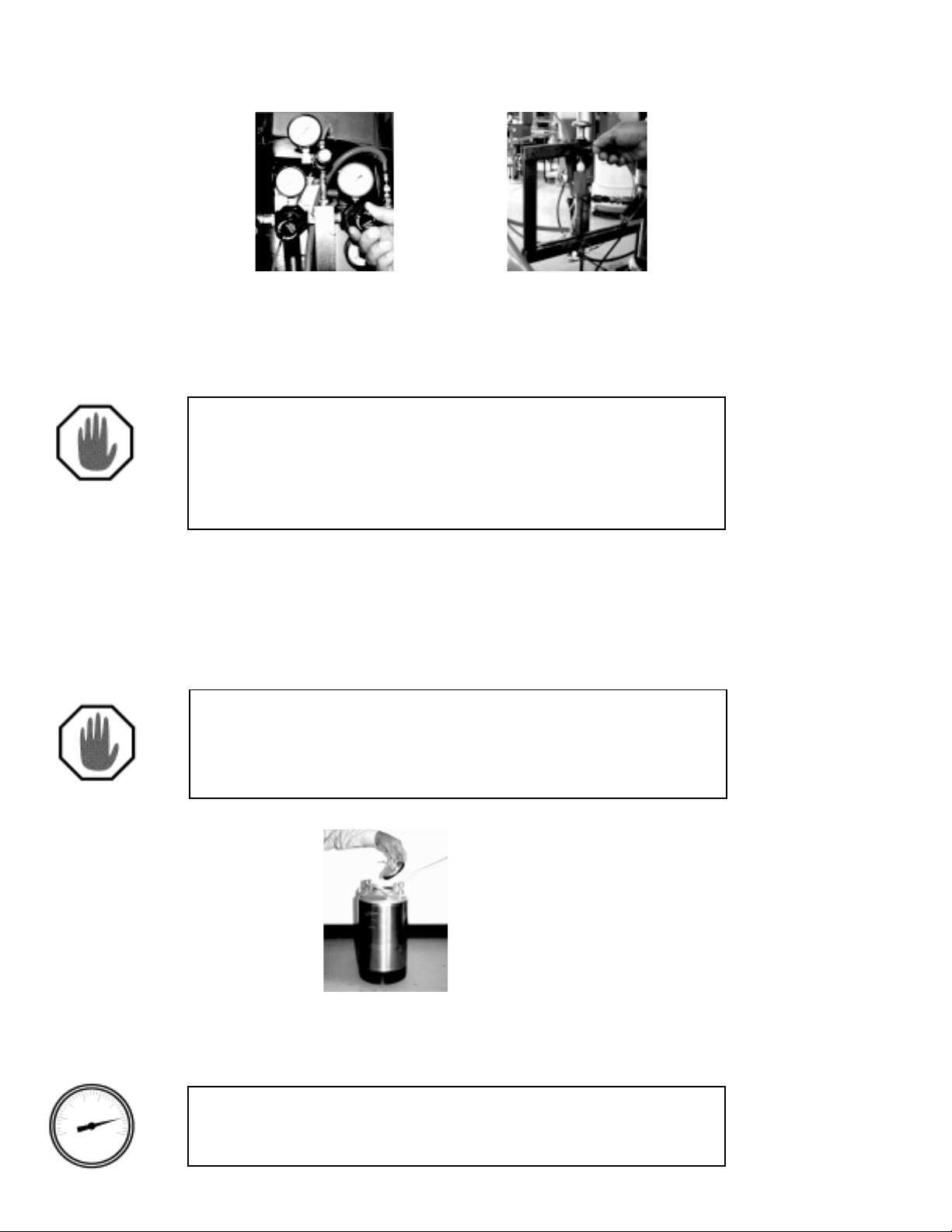
Fig. 2C
Fig. 2D
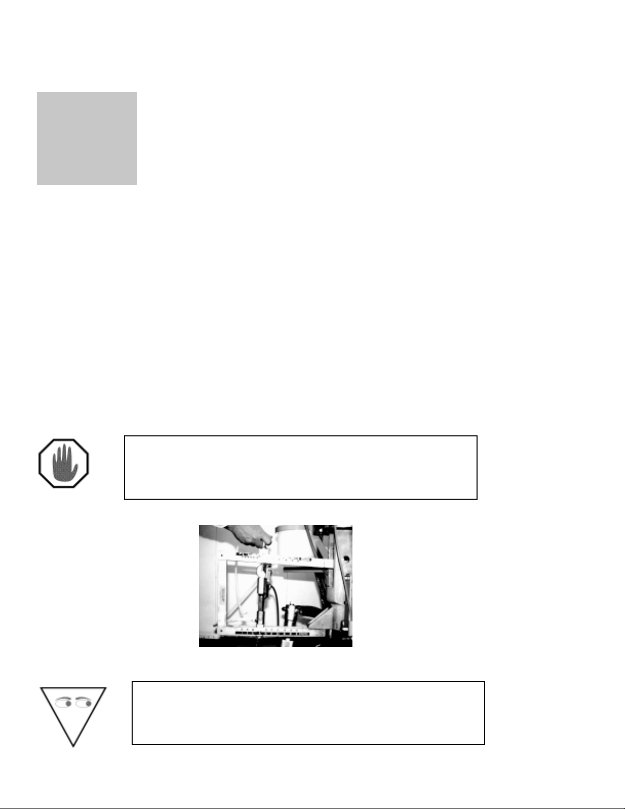
6. Slide catalyst pump toward the connecting arm and re-insert quick pin into
slave arm hole just in front of catalyst pump bearing block.
NOTE
This will allow resin pump to stroke, but prevent catalyst
pump from moving during start-up. Never have the
catalyst pump connected except when actually spraying
a laminate or damage to the catalyst system may occur.
7. Attach air source to manifold fitting.
8. Remove the lid from the flush tank and fill with clean suitable solvent.
Replace the lid. (See Fig. 2E)
NOTE
1/2” diameter (minimum) air hose with a recommended
100 psi of clean, dry air should be used for maximum
efficiency.
Fig. 2E
9. Slowly bring flush regulator up to 85 psi (turn clockwise).
CAUTION
Flush tank pressure should never be higher than 85 psi.
SUPERCHARGED H.I.S.™
2
Page 7
START-UP PROCEDURE
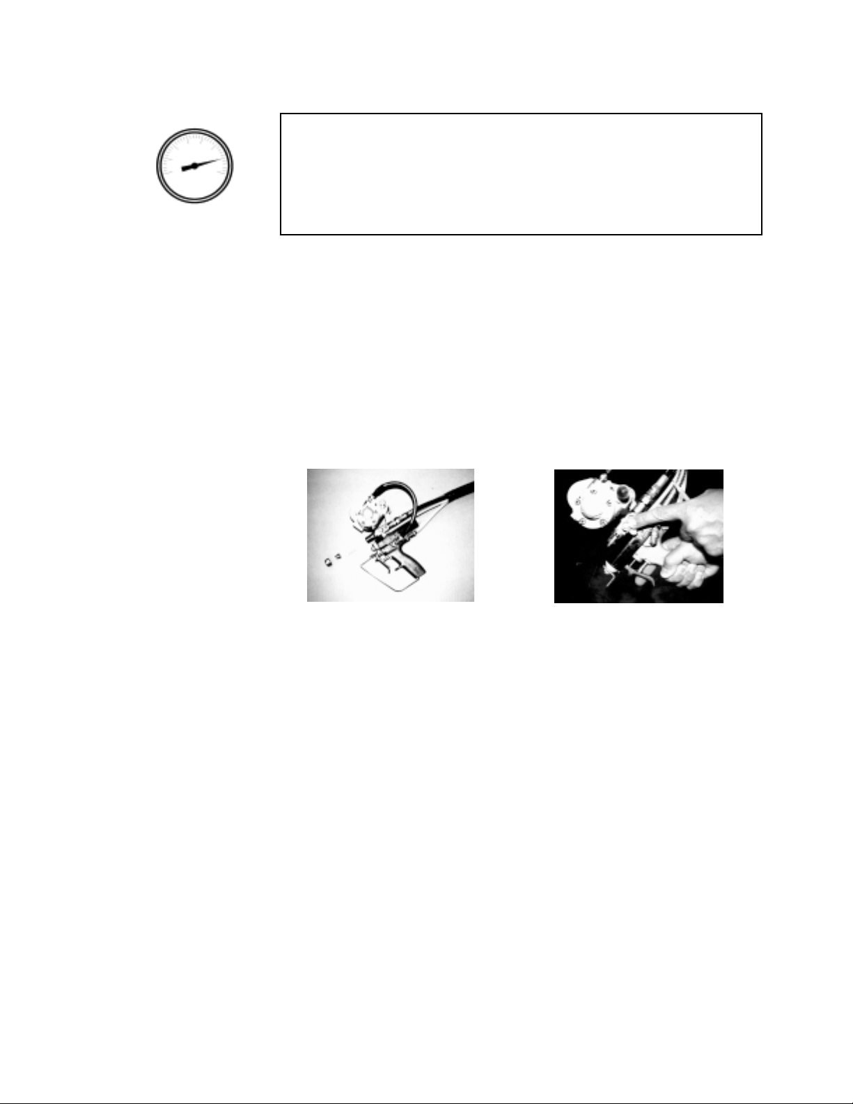
NOTE
Release pressure from flush system before any
corrective action takes place. To relieve pressure, turn
flush air control valve to off position and lift up on lever or
ring of relief valve located on top of flush tank.
10.Slowly open flush air control valve located on manifold.
1 1. Remove nozzle assembly, and turbulent mixer from gun. (See Fig. 2F)
12.Push flush button (located on the side of the gun block, see Fig. 2G)
untilsolvent exits the gun block. Release button and check entire flush
system for leaks.
Fig. 2F
Fig. 2G
13.Set the gun regulator (located on the manifold) between 90 and 100
psi.
14.Position gun over suitable container and pull trigger. Be sure gun
remains open during priming procedure.
3
SUPERCHARGED H.I.S.™
Page 8
Chapter
33
3
33
Priming the Catalyst Pump
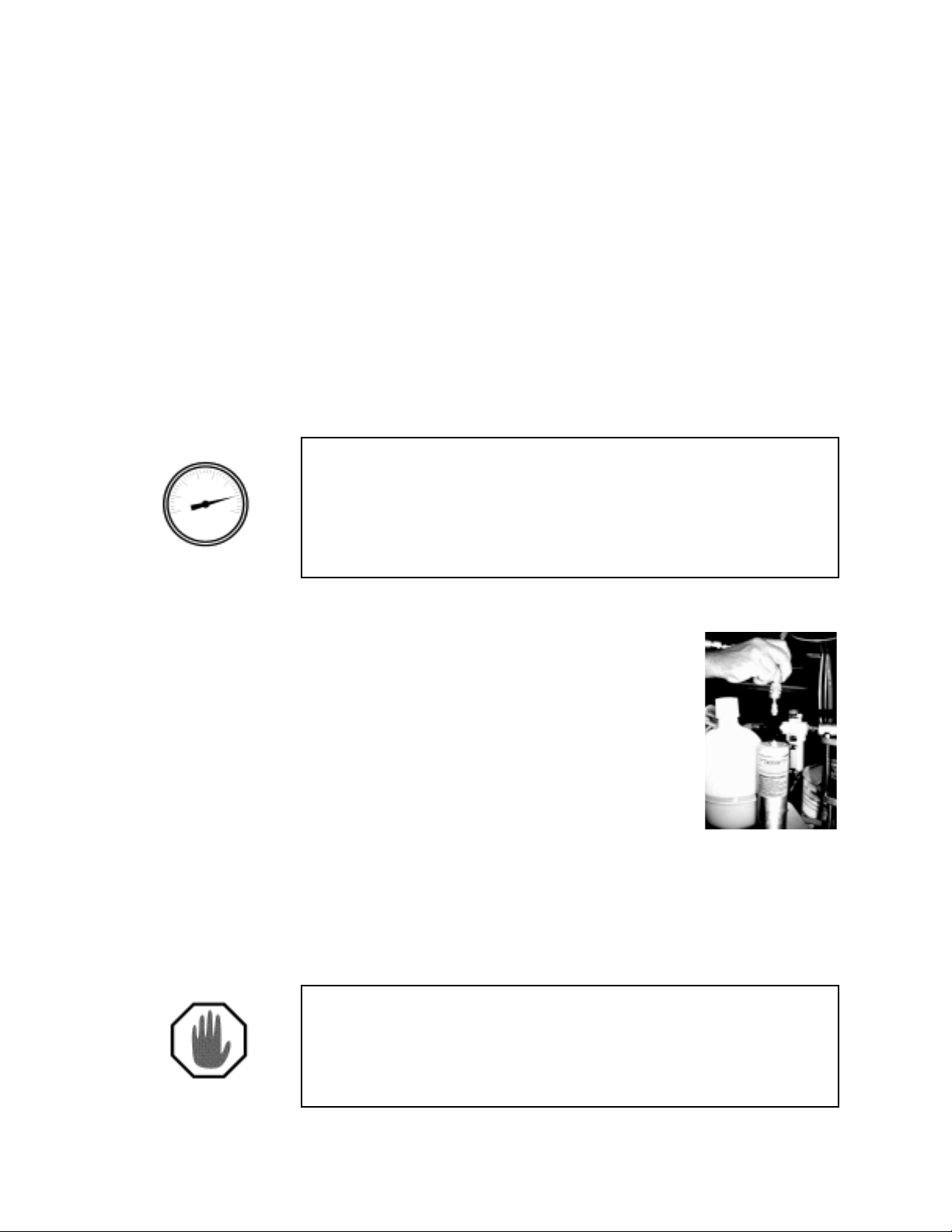
1. Carefully fill 2 gallon catalyst jug with MEKP (never dilute catalyst for MVP
systems.) Check for, and remove air voids in feed line.
2. Remove top quick pin from upper slave arm.
3. With steady even strokes, slowly hand pump the catalyst pump using priming
knob. Stop hand priming when steady stream of catalyst pours from the gun with
no air in the stream. (See Fig. 3A)
NOTE
See catalyst manufacturer for proper MEKP formulation for
your particular operation.
Fig. 3A
CAUTION
Always dispose of the waste catalyst according to the
manufacturer’s recommended procedure.
SUPERCHARGED H.I.S.™
4
Page 9
PRIMING THE RESIN PUMP
Priming the Resin Pump
1. Resin supply should be thoroughly mixed before being used. Central
bulk resin systems should have filter between supply and pump to prevent
clogging. Place resin supply adjacent to unit and insert resin wand into
resin container .
2. Open resin pump air valve.
3. Slowly turn pump operating air regulator (clockwise)until resin pump
is stroking steady , even strokes (approximately 10 to 20 psi).
NOTE
As resin enters the pump, you may have to increase psi
slightly in order to maintain even pump strokes.
Observe gun to make sure resin pours from the gun
block evenly with no air in the stream.
4. Shut off air to resin pump by:
-turning regulator to zero or
-turning off pump air control valve
5. Close gun and flush into suitable
waste container .
6. Position resin drain hose (located under
resin filter), into resin drum or suitable
waste container . Open resin drain ball valve.
7. Insert charging hose quick disconnect to
top of resin accumulator and hold down
for 10 seconds. Then remove. (See Fig. 3B)
NOTE
Although we recommend you pressurize the chamber,
in some cases there may not be a need to charge
depending upon material, pump pressure and tip size.
Fig. 3B
5
SUPERCHARGED H.I.S.™
Page 10

PRIMING THE RESIN PUMP
NOTE
Quick disconnect will not lock onto accumulator fitting.
This is intentional as it is not recommended to leave the
charging hose connected.
8. While holding charging hose on resin accumulator fitting, listen for air
exhausting from the resin dump hose. If no air is exhausting, proceed to
step 9. If air is heard exhausting, the accumulator ball is not seating
properly and the following procedure must be performed:
STOP
Fig. 3C Fig. 3D Fig. 2E
a. Be sure resin drain ball valve is open. (See Fig. 3C)
b. Remove air charge from resin accumulator by inserting 1/8” rod
(provided), into fitting on top of accumulator while pressing the
check valve. (See Fig. 3D & 3E)
c. Slowly unscrew accumulator from the accumulator adaptor .
Stop if accumulator is hard to unscrew by hand. This
may indicate that an air charge still exists in the
accumulator and cannot be discharged from the check
valve.
If this happens, continue to unscrew very slowly,
stopping once every revolution to allow pressure to
escape through the grooves into the threads of the
accumulator mounting nipple.
d. Clean accumulator and poly ball with a clean rag or solvent (if needed).
e. Reassamble.
f. Repeat steps 6 & 7.
9. Close the resin drain ball valve under the resin filter. (See Fig. 3C)
SUPERCHARGED H.I.S.™
6
Page 11

PRIMING THE RESIN PUMP
10.Install turbulent mixer and nozzle assembly onto the gun block. Align
nozzle (spray or flowchop) in horizontal position. NOTE: refer to the
nozzle chart in the H.I.S. System Instruction Manual for appropriate nozzle
selection.
1 1.Slowly open resin pump air valve and slowly turn pump operating
pressure regulator to recommended setting (40 to 50) psi. Resin and
catalyst pump will stroke until fluid line pressure is reached. Check all
fittings for leaks.
NOTE
Always remember to turn off regulator and slowly open gun
trigger to bleed system before any disassembly or repair
takes place.
12.Using priming knob, hand prime the catalyst pump until fluid pressure
resistance is felt in the stroke.
13.Connect catalyst pump to slave arm using the quick pins to desired
setting.
CAUTION
To avoid damage to the catalyst pump, always connect
quick pins to the same percentage holes on the upper and
lower slave arm.
7
SUPERCHARGED H.I.S.™
Page 12

Chapter
44
4
44
Creating a Proper Spray P attern
1. Adjust resin pump operating pressure to desired (40 - 50 psi) setting. Check
resin pump operating pressure gauge while gun is in operation to ensure system
is running at proper level.
OPERA TING PRESSURES
For line charge applications the following minimum
operating pressures are recommended:
FlowChop and Flow Coat applications 40 psi
Spray applications 45 psi
Critical Mix Turbulent Mixers are required when operating
pressures are below 60 psi. Use Standard Turbulent Mixer
foroperating pressures above 60 psi.
2. Prepare spray test surface (typically , large sheets of paper or cardboard).
3. Spray one slow , even pass on test surface. Observe spray pattern.
n If fan is very narrow with heavy “fingers” on inside and outside of pattern
(Fig. 4A), increase resin pump regulator 5 psi and repeat spray test.
Fig. 4A
SUPERCHARGED H.I.S.™
8
Page 13

CREATING A PROPER SPRAY PATTERN
n If fan is misting or fuming and a heavy white looking froth appears in
the resin that does not disappear, the operating pressure may to too high for
the nozzle and resin being used.
n A good consistent spray fan will have slight “horns” on the outside
edges. It will have the correct angle for the nozzle used, very little misting, or
excessive fumes being generated. NOTE: A slight frothing
may occur but should dissipate in approximately 1 to 2 minutes.
Three major factors in creating a proper spray pattern are:
1. Resin temperature
Resin at proper temperature as indicated in the resin manufacturer’s
material data sheet will eliminate many adjustments.
2. Correct nozzle
Numbers marked on each nozzle will inform you of nozzle angle and
approximate output. A variety of nozzles are available. Consult the MVP
nozzle chart or contact your local MVP distributor . NOTE: A good rule of
thumb is to always increase nozzle size rather than air pressure for greater
output.
3. Air pressure
Additional air pressure should only be used after option 1 and 2 have
been checked. Increasing or decreasing air pressure should only be done to
achieve correct fan pattern and not as a means of controlling output. Most
misting, fuming and fogging are a result of incorrect air pressure settings.
Once correct settings have been achieved, observe fan to determine if resin
is being delivered evenly without any “pulsation.” If no pulsation is observed,
the system is ready for operation.
If pulsation occurs:
• Check and clean resin filter
Increase back pressure in gun by doing one or a combination of the following:
• Using Critical Mix Turbulent Mixer (part #55000-1)
• Reducing nozzle orifice size (For nozzle options, consult your local
MVP Distributor .)
• Increase operating pressure
NOTE
The Critical Mix Turbulent Mixer (part #55000-3) is
always recommended when operating pressures are
below 60 psi.
9
SUPERCHARGED H.I.S.™
Page 14

Chapter
55
5
55
Shut-Down Procedure
1. Turn the resin pump air valve to the of f position. Leave gun air supply at 90 to
100 psi.
2. Pull the top quick pin from the catalyst pump slave arm. Slide catalyst pump
toward the connecting arm and re-insert quick pin into slave arm hole just in front
of catalyst pump bearing block. (See Fig. 5A)
Fig. 5A
CAUTION
This will allow resin pump to stroke, but prevent catalyst pump
from moving during Shut-down procedure. It should be
general procedure to never have the catalyst pump connected
except when actually spraying a laminate.
3. Remove nozzle assembly and turbulent mixer from gun. Clean these parts
and set aside. Check for wear.
4. Hold gun over suitable container and pull trigger allowing resin and catalyst
fluid pressure to drain completely .
SUPERCHARGED H.I.S.™
10
Page 15

SHUT-DOWN PROCEDURE
5. Flush gun and wipe gun block clean.
6. Check and fill resin pump power head oiler if necessary .
7. Drain water trap located on air manifold.
8. Check pump packing for leaks. Resin leaking into the pump casting
oil reservoir indicates the packings need replacement.
9. Turn flush valve located on the manifold to off position.
10.Relieve flush tank pressure by lifting up on the lever or ring of the relief
valve located on top of the flush tank.
Fig. 5B
11
SUPERCHARGED H.I.S.™
Page 16

Chapter
66
6
66
Remo ving Materials
F rom The System
You may find a need to remove materials from the system periodically if you plan
a long term shut-down, are changing resin types or are making other material
switches.
NOTE
These steps may be followed when performing maintenance, or
for shutting the system down for long periods of time. Follow
steps 1 through 10 of the shut-down procedure before the
beginning of material removal.
1. Remove resin wand from material and allow to drain.
2. Place wand in approximately 2 gallons of solvent and clean wand.
3. Aim gun into suitable container and carefully open gun by pulling trigger .
Lock trigger open.
4. Open resin pump air valve and turn resin pump regulator up until pump
begins tostroke even, slow strokes. Continue to cycle solvent through resin
system until solvent appears clean. Note: Additional solvent may be required
depending onhow clean the unit needs to be.
5. Shut off resin regulator , and close resin pump air valve.
6. Remove the charge from the resin accumulator by inserting a 1/8” diameter
rod(provided) into fitting at the top the resin accumulator . Keep rod pushed
against the check valve until all air is exhausted. (See Fig. 6A & 6B)
SUPERCHARGED H.I.S.™
12
Page 17

REMOVING MATERIALS FROM THE SYSTEM
7. Place suitable container under the resin filter and slowly unscrew the filter
tank from the filter body .
STOP
Fig. 6A
Fig. 6B
8. Clean filter tank, filter screen and filter core in solvent.
NOTE
The resin filter will need cleaning on a regular basis
depending on the material used. Filter screen will show
the degree of contaminates to judge cleaning intervals. It
is not necessary to completely flush resin system to clean
filter, but follow proper fluid pressure bleeding
procedure before removing the filter.
9. Slowly unscrew accumulator.
Stop if accumulator is hard to unscrew by hand. This
may indicate than an air charge still exists in the
accumulator and cannot be discharged from the check
valve.
If this happens, continue to unscrew very slowly,
stopping once every revolution to allow pressure to
escape through the relief cut into the threads of the
accumulator mounting nipple.
CAUTION
Always wear safety glasses and protective clothing.
CAUTION
The accumulator should be cleaned weekly to prevent resin
gelation.
10. Clean the accumulator in solvent.
13
SUPERCHARGED H.I.S.™
Page 18

REMOVING MATERIALS FROM THE SYSTEM
1 1.T o remove the catalyst from the system, only use clean distilled water. W ash
all parts thoroughly and blow dry .
NOTE
Catalyst has a much longer shelf life than resin, and
therefore does not need to be removed from the system as
often. See catalyst manufacturer for shelf life specifications.
System can now be stored for an intermediate amount of time (2 - 3 weeks)
or broken down for maintenance.
SUPERCHARGED H.I.S.™
14
Page 19

Chapter
77
7
77
Reassembly of Resin Accumula tor
and Resin Filter
1. Grease accumulator nipple threads and O-ring with MVP white grease.
Check O-ring for damage and wear. Replace if necessary .
2. Place poly ball on top of nipple.
3. Screw accumulator body onto nipple. Hand tight only .
4. Grease threads of the filter tank.
5. Place filter core into filter screen.
The pin on the core must enter the filter screen.
6. Place screen and core into tank
The pin end of the core and screen goes into the tank first.
The core and screen will rest against the spring in the
bottom of the filter tank.
NOTE
NOTE
7. Screw the filter tank, core and screen into bottom of filter body . Hand tight
only.
15
SUPERCHARGED H.I.S.™
Page 20

SUPERCHARGED H.I.S.™
16
Page 21

17
SUPERCHARGED H.I.S.™
Page 22

SUPERCHARGED H.I.S.™
18
Page 23

19
SUPERCHARGED H.I.S.™
Page 24

SUPERCHARGED H.I.S.™
20
Page 25

NOTES
SUPERCHARGED H.I.S.™
Page 26

NOTES
SUPERCHARGED H.I.S.™
Page 27

SUPERCHARGED H.I.S.™
Page 28

Corporate HQ/Mfg. MVP T echnology Center
5148 113th A ve. 1862 Ives A ve.
Clearwater, FL 33760 Kent, WA 98032
Tel: (727) 573-2955 Tel: (253) 854-2660
Fax: (727) 571-3636 Fax: (253) 854-1666
SUPERCHARGED H.I.S.™
E-mail: info@mvpind.com · Web: www .mvpind.com
© 2001 Magnum Venus Product s Manual Part No: 90084-1
 Loading...