

Page 1
FRP SystemOne
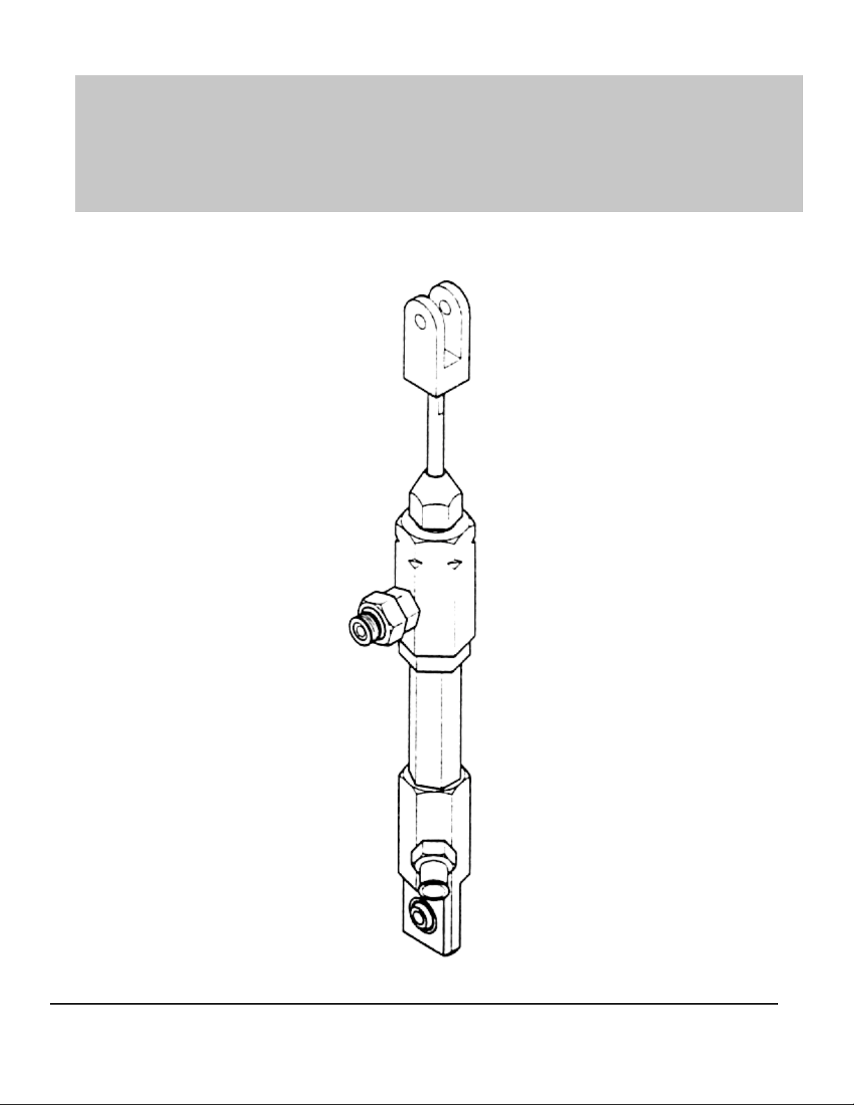
4101-00-01 Gelcoat Metering Pump
MAGNUM VENUS PRODUCTS
Maintenance & Repair Manual
Part No. M6704-4-1
FRP SystemOne
Revision 04.09.01
Gelcoat
Page 2

FRP SystemOne
Maintenance & Repair Manual
Gelcoat Metering Pump Module
FRP SystemOne
Gelcoat
MVP Manufacturing/Sales
Phone: (253) 854-2660 (800) 448-6035
Fax: (253) 854-1666
Email: info@venusmagnum.com
Web: www .venusmagnum.com
MVP Corporate HQ/Manufacturing
Phone: (727) 573-2955
Fax: (727) 571-3636
Email: info@magind.com
Web: www .magind.com
© 2001 Magnum Venus Product s Manual Part No: M6704-4-1
Page 3

Table of Contents
FRP SystemOne
Maintenance & Repair Manual
Gelcoater Metering Pump Module
CHAPTER 1 - GETTING ST ARTED
T ools Required
CHAPTER 2 - INSTRUCTIONS
Disassembly of Metering Pump
CHAPTER 3 - INSTRUCTIONS
Disassembly of Catalyst Surge Chamber
CHAPTER 4 - INSTRUCTIONS
Reassembly of Metering Pump
CHAPTER 5 - INSTRUCTIONS
Reassembly of Catalyst Surge Chamber
CHAPTER 6 - APPENDIX
Parts Drawings
FRP SystemOne
Gelcoat
Page 4

Chapter
1
FRP SystemOne
Gelcoat Metering Pump
Getting Started
Tools Required
1. 1” Open End Wrench
2. 3/4” Open End Wrench
3. 5/8” Open End Wrench
4. 6” Adjust able Wrench (2 required)
5. 12” Adjustable Wrench
6. 1/4” Wood Dowel – 6” long
FRP SystemOne
Gelcoat
1
Page 5
Chapter
2
FRP SystemOne
Disassembly of MP.057S1 Gelcoat
Metering Pump
W ARNING
Before removing Metering Pump and Surge Chamber assembly
from the Slide Drive, be sure to bleed the fluid pressure from the
system; before disconnecting any hoses or tubes. System may be
under pressure and could cause injury.
1. Remove 4101-15-1 (Check V alve Body) from 4101-14-1 (Outlet
Body) and remove and discard the two 7301-4-013 (O-Rings).
2. Remove the 4107-17-1 (Spring Ret ainer) and 4101-16-1
(Compression Spring) from the 4101-15-1 (Check V alve Body),
and remove and discard the 9201-1-7 (7/32” SS Ball).
3. Loosen 4101-1-1 (Lock Nut) and unscrew the 4101-14-1 (Outlet
Body) from the 4101-2-1 (Cylinder).
4. Remove the 4101-61 (Seal Retainer) from the 4101-4-1 Piston
Body .
5. Remove and discard the 7304-2-1 (Piston Seal).
6. Remove the 4101-4-1 (Piston Body) from the 4101-10-1 (Piston
Rod).
2
FRP SystemOne
Gelcoat
Page 6
WARNING
Use wrench flats provided in order to avoid damaging the Piston
Rod.
7. Remove and discard the 9201-1-5 (5/32” SS Ball).
8. Remove and retain the 4101-3-1 (Piston Rod Spring).
9. Unscrew the 4101-1 1-1 (Packing Nut) and pull the 4101-10-1
(Piston Rod) out of the 4101-14-1 (Outlet Body).
NOTE
Carefully pull the Piston Rod out of Cylinder to avoid damaging
the interior surface of Cylinder. Inspect the Piston Rod for
scratches or other damage. Replace if necessary .
10. Insert a 1/4” diameter dowel into the bottom of the 4101-14-1
(Outlet Body), force the 4101-13-01 (Piston Rod Packings) and
4101-12-1(Upper Guide) out through the top of the Outlet Body and
discard.
NOTE
Care must be taken to not damage the inside of the Outlet Body .
1 1. Unscrew the 4101-2-1 (Cylinder) from the 4101-7-1 (Inlet Body).
Remove and discard the two 7301-9-014 (O-Rings). Inspect the
Cylinder for scratches, or other damage, and replace if necessary .
12. Remove and discard the 9201-1-14 (7/16” SS Ball). Inspect the
seat inside the 4101-7-1 (Inlet Body), for nicks, scratches, or other
damage, and lap, or replace if necessary .
13. Remove the 4101-8-1 (Tube Fitting). Remove and discard the
7301-9-013 (O-Ring).
NOTE
Once disassembly is complete all parts should be flushed in
distilled water and inspected for damage and replaced if
necessary .
FRP SystemOne
Gelcoat
3
Page 7
Chapter
FRP SystemOne
CS1S1 Gelcoat Catalyst Surge
Chamber Disassembly
W ARNING
Before removing metering pump and catalyst surge chamber
assembly from teh slide drive, be sure to bleed the fluid
pressure from the system; before disconnecting any hoses or
tubes. System may be under pressure and could cause injury .
3
1. Loosen the 4101-18-1 (Jam Nut), and remove the 4104-8-1
(Gauge Adapter) from the 4104-4-1 (Surge Relief Valve Body).
2. Remove and discard the 7301-4-013 (O-Ring).
3. Remove the 4104-6-1 (Return Tube Fitting) from the 4104-4-1
(Surge Relief V alve Body).
4. Remove and discard the 7301-4-013 (-Ring), and the 9201-1-4
(1/8” SS Ball).
NOTE
This is all the disassembly that is required to install the repair
kit. Further disassembly is required if there is a problem with
the 8701-1-1 (Burst Disc).
NOTE
Once disassembly is complete all parts should be flushed in
distilled water and inspected for damage and replaced if necessary .
4
FRP SystemOne
Gelcoat
Page 8
Chapter
4
FRP SystemOne
Reassembly of MP .057S1
Gelcoat Metering Pump
Assembly Procedures:
1. Install 7301-9-013 (O-Ring), and 4101-8-1 (Inlet Tube Fitting) onto
4101-7-1 (Inlet Body).
2. Insert the 9201-1-14 (7/16” SS Ball) into the 4101-7-1 (Inlet Body).
NOTE
Care must be taken to not scratch or dent SS Ball.
3. Position a 7301-9-014 (O-Ring) onto the notched end of the
4101-2-1 (Cylinder).
NOTE
Take care not to damage the O-ring on the threads.
4. Screw the notched end of the 4101-2-1 (Cylinder) into the 4101-7-1
(Inlet Body). T urn by hand until it bottoms on the Inlet Body, “snug
tight”.
FRP SystemOne
Gelcoat
5
Page 9

5. Thread the 4101-1-1 (Lock Nut) onto the 4101-2-1 (Cylinder) until it
bottoms on the Cylinder shoulder .
6. Install a 7301-9-013 (O-Ring) onto the long threaded end of the
4101-2-1 (Cylinder).
7. Install the 4101-7-1 (Packing Nut), 4101-12-1 (Upper Guide) and
4101-13-01 (Packing Set) onto the 4101-10-1 (Piston Rod).
NOTE
See drawing for proper orientation.
8. Carefully insert the 4101-10-1 (Piston Rod) through the 4101-14-1
(Outlet body).
NOTE
Care must be taken to not scratch the Piston Rod.
9. Carefully press the 4101-13-1 (Piston Rod Packings), and
4101 12-1 (Upper Guide) into 4101-14-1 (Outlet Body).
NOTE
Care must be taken to not damage the Piston Rod Packings.
10. Screw the 4101-1 1-1 (Packing Nut) into the 4101-14-1 (Outlet
Body). Screw the Packing Nut until the Packings bottom in the
Outlet Body cavity . Lightly snug the packing nut with a wrench.
1 1. Insert the 4101-3-1 (Piston Rod Spring) into the 4101-10-1 (Piston
Rod).
12. Insert the 9201-1-5 (5/32” SS Ball) into the 4101-4-1 (Piston Body).
13. Screw the 4101-4-1 (Piston Body) onto the 4101-10-1 (Piston
Rod), compressing the 4101-3-1 (Piston Rod Spring) onto the
9201-1-5 (5/32” SS Ball).
6
FRP SystemOne
Gelcoat
Page 10

14. Install the 7304-2-1 (Piston Seal) onto the threaded end of the
4101-4-1 (Piston Body) spring side up.
NOTE
Note orientation of seal on drawing.
15. Install the 4101-5-1 (Piston Guide) onto the 4101-4-1 (Piston Body)
below the 7304-2-1 (Piston Seal).
16. Screw the 4101-6-1 (Seal Retainer) onto the 4101-4-1 (Piston
Body), hand tight.
17. Hold the 4101-10-1 (Piston Rod) with a wrench on the wrench
flats, and tighten the 4101-6-1 (Seal Retainer) with another
wrench.
18. Insert the Piston Rod assembly into the 4101-2-1 (Cylinder) s
crewing the 4101-14-1 (Outlet Body) onto the cylinder threads.
NOTE
Screw the Outlet body down until you feel the O-Ring start to
compress.
19. Align the 4101-14-1 (Outlet Body) so the outlet port is one hex flate
to the left of the inlet port of the 4101-7-1 (Inlet Body) See Fig. 4.1
Fig. 4.1
Offeset intake and outlet
ports one flat hex as
shown in figure.
FRP SystemOne
Gelcoat
7
Page 11

20. Place the 9201-1-7 (7/32” SS Ball) down inside the 4101-15-1
(Check V alve Body) through the double threaded side.
21. Install the 4101-16-1 (Compression Spring) into the 4101-15-1
(Check V alve Body) onto the top of the 9201-1-7 (7/32” SS Ball).
22. Screw the 4101-17-1 (Spring Ret ainer) into the inside of the
4101-15-1 (Check V alve Body), Compressing the Spring between
the Retainer and the SS Ball.
23. Place a 7301-9-013 (O-Ring) over the single threaded end of the
4101-15-1 (Check V alve Body), and screw the Check V alve into
the 4101-14-1 (Outlet Body).
24. Place a 7301-97301-9-013 (O-Ring over the double threaded end
of the 4101-15-1 (Check V alve Body) until it is in the thread relief
area between the two set of threads and against the end of the
4101-18-1 (Jam Nut).
The Metering Pump assembly is complete.
8
FRP SystemOne
Gelcoat
Page 12

Chapter
5
FRP SystemOne
CS1S1Gelcoat Catalyst
Surge Chamber Reassembly
1. Install a 7301-9-013 (O-Ring) over the threaded end of the
4104-6-1 (Return Tube Fitting).
2. Insert the 9201-1-4 (1/8” SS Ball) into the 4104-4-1 (Surge Relief
V alve Body).
3. Insert the 4104-5-1 (Relief V alve S pring) into the 4104-4-1 (Surge
Relief V alve Body) over the SS Ball.
4. Thread the 4104-6-1 (Return tube Fitting) into the 4104-4-1 (Surge
Relief V alve Body) compressing the spring between the Tube
Fitting and the Ball.
5. Fasten the Catalyst Surge Chamber Assembly to the Metering
Pump Assembly.
The Surge Chamber Assembly is complete.
FRP SystemOne
Gelcoat
9
Page 13

FRP SystemOne Gelcoater
Part s Drawings
Chapter
6
10
FRP SystemOne
Gelcoat
Page 14

MAGNUM VENUS PRODUCTS
FRP SystemOne
Gelcoat
11
Page 15

The parts for this repair kit are
included in the Metering Pump
Repair Kit, PN 6702-5-1
12
FRP SystemOne
Gelcoat
Page 16

MAGNUM VENUS PRODUCTS
FRP SystemOne
Gelcoat
13
Page 17

14
FRP SystemOne
Gelcoat
Page 18

MAGNUM VENUS PRODUCTS
FRP SystemOne
Gelcoat
15
Page 19

16
FRP SystemOne
Gelcoat
Page 20

MAGNUM VENUS PRODUCTS
FRP SystemOne
Gelcoat
17
Page 21

18
FRP SystemOne
Gelcoat
Page 22

FRP SystemOne
Gelcoat
Page 23

FRP SystemOne
Gelcoat
Page 24

FRP SystemOne
Gelcoat
MVP Manufacturing/Sales
Phone: (253) 854-2660 (800) 448-6035
Fax: (253) 854-1666
Email: info@venusmagnum.com
Web: www .venusmagnum.com
MVP Corporate HQ/Manufacturing
Phone: (727) 573-2955
Fax: (727) 571-3636
Email: info@magind.com
Web: www .magind.com
© 2001 Magnum Venus Product s Manual Part No: M6704-4-1
 Loading...