

Page 1
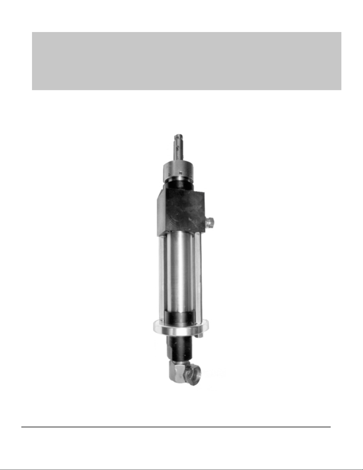
FRP SystemOne
3101-00-01 Fluid Section
Magnum Venus Products
Maintenance & Repair Manual
Part No. M3101-00-01
Revision 01.23.01
FRP SystemOne
Page 2

FRP SystemOne
Maintenance & Repair Manual
Fluid Section Module
Corporate HQ, Mfg.
Phone: (727) 573-2955
Fax: (727) 571-3636
Email: info@magind.com
Web: www .magind.com
FRP SystemOne
Manufacturing
Phone: (253) 854-2660 (800) 448-6035
Fax: (253) 854-1666
Email: info@venusmagnum.com
Web: www .venusmagnum.com
© 2001 Magnum Venus Product s Manual Part No: M3101-00-01
Page 3

T able of Contents
FRP SystemOne
Maintenance & Repair Manual
Fluid Section Module
CHAPTER 1 - GETTING ST ARTED
T ools Required
CHAPTER 2 - INSTRUCTIONS
Disassembly of Fluid Section
CHAPTER 3 - INSTRUCTIONS
Reassembly of Fluid Section
CHAPTER 4 - APPENDIX
Fluid Section Part Drawings
FRP SystemOne
Page 4

Chapter
1
FRP SystemOne
Fluid Section
Getting Started
Tools Required
1. ¾” open end wrench
2. ¼” wooden dowel-6”
3. ¼” metal rod
4. 12” adjustable wrench
5. Strap wrench
6. Spanner or Ford wrench
7. 9/16” Open End W rench
8. Pliers
FRP SystemOne
1
Page 5
FRP SystemOne
Disassembly of Fluid Section
WARNING
When removing Resin Pump Fluid Section and Resin Surge Chamber, be sure to bleed pressure from the system before disconnecting hoses or tie rods. Release Surge Chamber charge before
removing Surge Chamber. System may be under pressure and
could cause injury.
Chapter
2
NOTE
The resin pump can be rebuilt in place or easily removed from pump
column and moved to a workbench.
To remove the Fluid Section from the
SystemOne Unit:
1. Remove the 8401-5-1 (E-Ring), lift up the 8401-4-1 (Sleeve) and
remove the two 8401-3-1 (Connectors).
2. Remove the 4103-1-1 (Pivot Pin Guide Bushing) to disengage the
from the 4103-7-1 (Slide Arm).
3. Remove the 7201-8-1 (Quick Pin) and slide the 4103-7-1 (Slave
Arm) out of the 3101-8-1 (Piston Rod Adapter).
2
FRP SystemOne
Page 6

Fluid Section Disassembly Procedures:
1. Remove the two 7201-6-8 (Hex Nuts) from the 3101-20-1 (Pump
Cylinder Tie Rods).
2. Slide the 3101-21-1 (Foot Valve Collar), 3101-19-1 (Foot Valve) and
3101-16-1 (Cylinder) down off the 3101-9-1 (Piston Rod), discard
the T wo 7301-1-137 (O-Rings). Remove the 3101-17-1 (Ball S top)
and 3101-18-1 (Foot V alve Spring). Remove and discard the
9201-2-36 (1 1/4” Chrome Ball). Clean and inspect ball seat area of
3101-19-1 (Foot V alve).
3. Loosen 3101-1-1 (Packing Nut) and slide the 3101-9-1(Piston Rod)
out the bottom of the 3101-7-1 (Outlet Body).
4. Unscrew the 3101-15-1 (Piston Nut) from the 3101-11-1 (Piston
Body). Remove the two 3101-12-1 (Piston Cups), 3101-14-1
(Piston Cup Back-up) and 3101-13-1 (Piston Cup Spacer) from the
3101-11-1 (Piston Body). Discard the two 3101-12-1 (Piston Cups).
5. Unscrew the 3101-11-1 (Piston Body) from the 3101-9-1 (Piston
Rod). Remove the 9201-2-28 (7/8” Chrome Ball) and the 3101-10-1
(Piston Ball Spring) Discard the 9201-2-28 (Chrome Ball – 7/8”)
6. Remove the 3101-1-1 (Packing Nut) from the 3101-7-1 (Outlet
Body). Use a 1/4” wooden dowel to push the 3101-4-01 (Packing
Set Assembly) out the top of the 3101-7-1 (Outlet Body). Discard
the packing set. Clean and inspect the 3101-2-1 (Guide Bearing),
3101-3-1 (Female Compression Ring), 3101-5-1 (Male
Compression Ring), 9203-1-1 (Wave Spring), and 3101-6-1 (Spring
Support Ring).
7. Clean and inspect all parts that will be reused, replace as needed.
FRP SystemOne
3
Page 7

Chapter
3
FRP SystemOne
Reassembly of Fluid Section
1. Use MVP 6706-2-1 (White Grease) to fill in the female side of each
of the four Packings in the 3101-4-01 (Packing Set Assembly) and
the 3101-3-1 (Female Compression Ring). Wipe a light coat of
White Grease on the 9201-2-28 (7/8” Chrome Ball), and the 9201-236 (1 1/4“ Chrome Ball). Smear White Grease on the inner radius
on both 3101-12-1 (Piston Cups). Coat the threads on the 3101-1-1
(Packing Nut) with the White Grease.
2. Insert the 3101-6-1 (Spring Support Ring) into the 3101-7-1 (Outlet
Body), followed by the ten 9203-1-1 (Wave Springs). Place the
3101-4-01 (Packing set Assembly) on top of the 3101-5-1 (Male
Compression Ring). Set the 3101-3-1 (Female Compression Ring )
on top of the 3101-4-01 (Packing Set Assembly). Place the entire
assembly into the 3101-7-1 (Outlet Body) with the female side of the
Packing Set facing down. Set the 3101-2-1 (Guide Bearing) into
the 3101-7-1 (Outlet Body). Screw the 3101-1-1 (Packing Nut) into
the 3101-7-1 (Outlet Body) only two to three threads.
NOTE
Do not tighten the 3101-1-1 (Packing Nut) at this time.
4
FRP SystemOne
Page 8
3. Slide one 3101-12-1 (Piston Cups) onto the 3101-11-1 (Piston
Body) with the open side of the Piston Cup facing up. Slide the
3101-13-1 (Piston Cup Spacer) with grooved side up against the
Piston Cup. Install the second 3101-12-1 (Piston Cup) up against
the Piston Cup Spacer with the open side up. Slide the 3101-14-1
(Piston Cup Back-up) with grooves facing up against the Piston
Cup. Coat the threads of the 3101-15-1 (Piston Nut), and screw it
onto the 3101-11-1 (Piston Body). Place 9201-2-28 (7/8” Chrome
Ball) into the 3101-11-1 (Piston Body). Set the 3101-10-1 (Piston
Ball Spring) into the Piston Body with the small end of the spring
against the 9201-2-21 (7/8” Chrome Ball).
NOTE
Do not drop, dent, or scratch the 9201-2-28 (7/8” Chrome Ball)
4. Coat the threads of the 3101-11-1 (Piston Body), and screw it onto
the 3101-9-1 (Piston Rod). Tighten the 3101-15-1 (Piston Nut) and
the 3101-11-1 (Piston Body) wrench tight.
5. Slide the 3101-9-1 (Piston Rod) up through the 3101-7-1 (Outlet
Body) and tighten the 3101-1-1 (Packing Nut) enough to hold the
Piston Rod in place.
6. Install 9201-2-36 (1 1/4” Chrome Ball), then the 3101-18-1 (Foot
Valve Ball Spring) into the 3101-19-1 (Foot Valve). Compress the
3101-17-1 (Ball Stop) and insert it into the 3101-19-1 (Foot Valve)
groove. Position one end of the 3101-16-1 (Cylinder) into the 310119-1 (Foot V alve).
7. Use lithium grease on the 3101-20-1 (Pump Cylinder Tie Rod)
threads and screw into 3101-7-1 (Outlet Body) if they were removed.
NOTE
The two 3101-20-1 (Pump Cylinder Tie Rods) must be inserted in
opposing holes.
8. Slide the 3101-16-1 (Cylinder) with 3101-19-1 (Foot Valve) over the
Piston Rod Assembly and st art the 7201-6-8 (Hex Nut s) onto the
3101-20-1 (Pump Cylinder Tie Rods). Tighten uniformly until
wrench tight.
9. Use a 1/4” metal rod, or Phillips screwdriver to tighten the 3101-1-1
(Packing Nut).
FRP SystemOne
5
Page 9

To Reinstall onto SystemOne Unit
1. Position the 8401-4-1 (Sleeve) over the Power Cylinder Piston
Shaft. Bring the Power Cylinder Piston Shaft down onto the top of
the 3101-8-1 (Piston Rod Adapter). Insert the two 8401-3-1 (Connectors) and lower the 8401-4-1 (Sleeve). Install the 8401-5-1
(Ring) in machined groove.
2. Slide the end of the 4103-7-1 (Slide Arm) into the slot in the 3101-81 (Piston Rod Adapter) and insert the 7203-8-1 (Quick Pin).
3. Fill the packing nut cavity 1/2 to 2/3 full with appropriate oil.
FRP SystemOne
Page 10

FRP SystemOne
Page 11

FRP SystemOne
Appendix
Parts Drawings
Chapter
4
6
FRP SystemOne
Page 12

Magnum Venus Products
FRP SystemOne
7
Page 13

8
FRP SystemOne
Page 14

Magnum Venus Products
FRP SystemOne
9
Page 15

10
FRP SystemOne
Page 16

Magnum Venus Products
FRP SystemOne
11
Page 17

12
FRP SystemOne
Page 18

Magnum Venus Products
FRP SystemOne
13
Page 19

14
FRP SystemOne
Page 20

Magnum Venus Products
FRP SystemOne
15
Page 21

16
FRP SystemOne
Page 22

Magnum Venus Products
FRP SystemOne
17
Page 23

18
FRP SystemOne
Page 24

Corporate HQ, Mfg.
Phone: (727) 573-2955
Fax: (727) 571-3636
Email: info@magind.com
Web: www .magind.com
© 2001 Magnum Venus Product s Manual Part No: M3101-00-01
FRP SystemOne
Manufacturing
Phone: (253) 854-2660 (800) 448-6035
Fax: (253) 854-1666
Email: info@venusmagnum.com
Web: www .venusmagnum.com
 Loading...