

Page 1
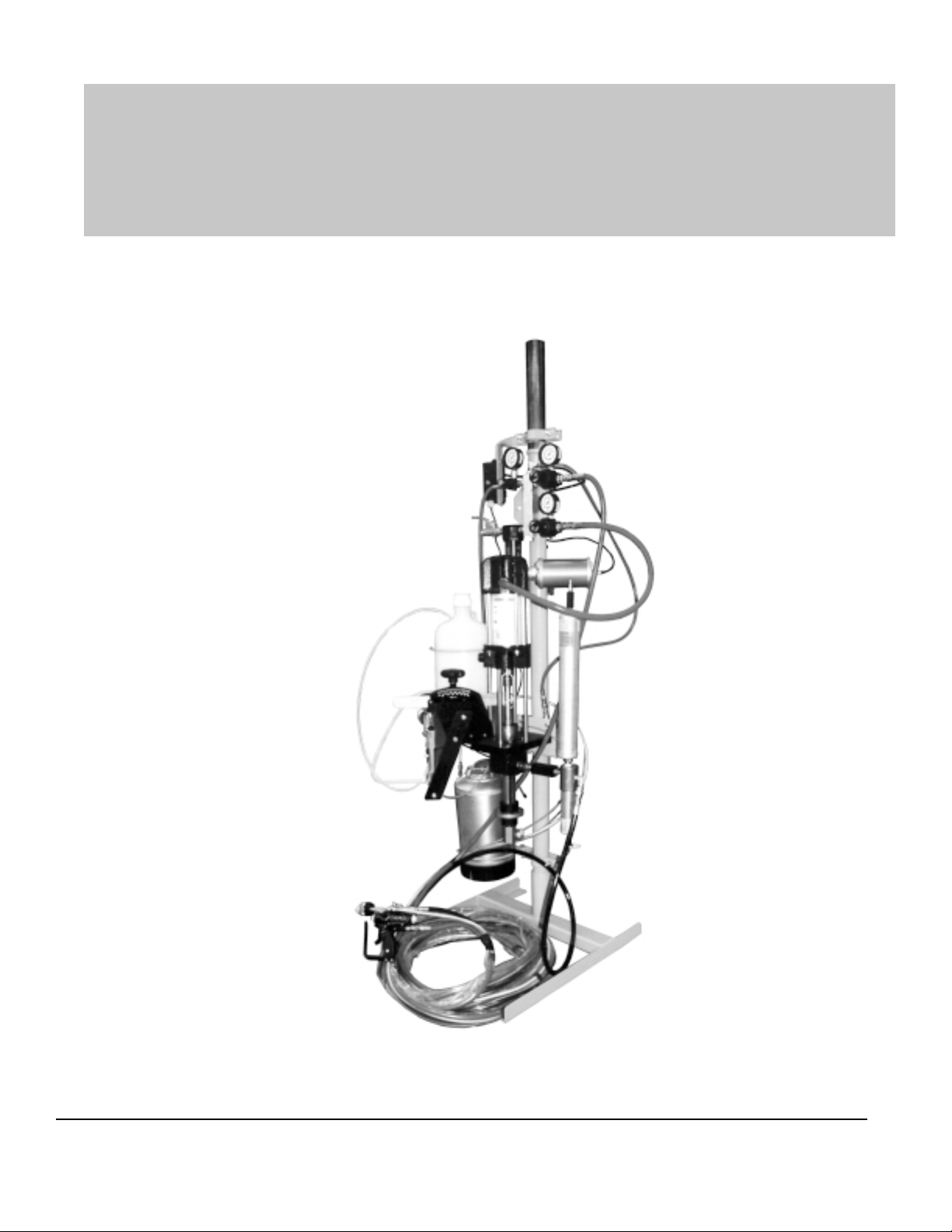
FRP SystemOne
1300-1-1 GELCOA TER OPERA TION MANUAL
MAGNUM VENUS PRODUCTS
Operation Manual
Part No. M1300-1-1
Revision 04.26.01
FRP SystemOne
Gelcoater
Page 2

Unit #
Type Of:
FRP SystemOne
Gelcoater Operation Manual
Unit Information
Power Cylinder
Metering Pump
Gun
Fluid Section
FRP SystemOne
Gelcoater
Page 3

T able of Contents
FRP SystemOne
Gelcoater Operation Manual
CHAPTER 1 - QUICK LIST
Start Up
Installation & Setup
CHAPTER 2 - GETTING ST ARTED
Installation & Setup
Pre-Operation Checklist
CHAPTER 3 - OPERATION
Wetting Unit
Proper Operating Pressures
Gun Set-Up
CHAPTER 4 - MAINTENANCE
CHAPTER 5 - PARTS DRAWINGS
Unit Assembly
Mounting Column Assembly
Cart Assembly
Pneumatic Manifold Assembly
3-Gallon Flush T ank Assembly
Catalyst Jug Assembly
Power Cylinder (4.25”) Assembly
Resin Filter Assembly
Drum Suction Wand Assembly
Surge Chamber Assembly
FRP SystemOne
Gelcoater
Page 4

Chapter
1
FRP SystemOne Gelcoater
Quick List Instructions
Start-Up Sheet
1. Check & fill solvent system
2. Check & fill resin & catalyst supply
3. Place suction wand in resin supply
4. Prime resin pump
5. Prime catalyst pump and set catalyst percentage
6. Check system for fluid leaks
7. Set air pressure to gun
8. Install turbulent mixer in mix chamber
9. Select & install nozzle
10. Adjust fan pattern
NOTE: These instructions include resin and catalyst pressurization
procedures. To avoid equipment malfunction or possible injury, please follow
these instructions. If you have any questions, please contact our Technical
Service Department at 800-448-6035.
FRP SystemOne
Gelcoater
1
Page 5
FRP
System
One Gelcoater
Quick List Instructions
Installation & Setup
1. Unpack unit &
components
2. Place unit & stand pipe in
base plate or portable cart (or
mount to wall with wall brackets)
Tighten bolts to secure
3. Install catalyst jug
4. Install resin surge chamber &
filter assembly
5. Install manifold air hose to power
cylinder
6. Attach hose fittings to resin
pump, catalyst pump, air &
flush tank
7. Install boom to mast
(if applicable)
8. Hang hose on boom
(if applicable)
9. Attach pickup hose
10. Place flush tank in holder and
attach air hose from manifold
11. Double check all hose fittings
2
FRP SystemOne
Gelcoater
Page 6

Chapter
2
FRP SystemOne Gelcoater
Getting St arted
Installation
1. Remove unit from crate.
With the crate lying flat, open the top panel and remove the
components:
a. Floor mount assembly
b. Gelcoat pump and pump column
c. Gun and hose set
d. Resin filter and surge chamber assembly
e. Suction wand assembly
f. Catalyst jug
g. Solvent tank
h. Catalyst pump
i. Air manifold
2. Assemble pump and column to floor mount assembly.
a. Slide pump column into floor mount and tighten the two hex bolts
in floor mount.
3. Assemble resin filter/surge chamber assembly to pump.
a. Check to make sure all Filter/Surge chamber connections are
tight.
b . Attach the filter/surge chamber assembly to the swivel fitting
located at the outlet of the resin pump.
c. With the filter/surge chamber assembly vertical. Tighten the
fitting with a wrench until it is tight.
FRP SystemOne
Gelcoater
3
Page 7

4. Mount catalyst jug bracket.
a. Attach the Catalyst jug bracket to the base of the catalyst pump
slide drive support.
b . Mount the bracket so it extends to the left side of the slide drive
support as you stand facing the end of the slide drive.
5. Mount solvent tank retainer bracket.
a. Attach the tank bracket to the column approximately 2 to 3
inches from the top of the floor mount frame round tube.
b. The bracket should be on the left side of the column as you face
the unit. Position the bracket so the tank will sit on the floor
mount square tubing. Tighten the flush t ank bracket bolts to the
column.
c. Remove the solvent tank from the carton and place into bracket.
6. Attach catalyst pump.
NOTE
If SystemOne Gelcoater unit is configured with a catalyst
alarm, please refer to the catalyst alarm manual when you
reach this stage of set-up.
a. Mount the Catalyst pump to the slide drive bracket using the
clevis pins and keepers provided.
b. The bottom of the catalyst pump is pinned to the lower leg of the
slide drive bracket.
c. The upper clevis, (piston rod), is pinned to the slide drive using
the forward of the long slot in the slide drive.
d. Hold the clevis pins in place with the wire keepers by placing
them in the holes in the clevis pins.
7. Mount air supply manifold.
a. Clamp manifold assembly to the pump column above the power
cylinder of the resin pump.
b. Regulators and gauges should face to the pump side of the
column.
c. Clamp yoke tight enough so the assembly does not move
around the column.
8. Attach suction wand to gelcoat pump.
a. Check all fittings on the wand assembly to make sure they are
airtight.
b. Attach the wand assembly to the foot valve swivel fitting and
tighten.
4
FRP SystemOne
Gelcoater
Page 8

9. Make hose connections.
a. Connect the black resin hose from the gun to the outlet fitting on
the resin filter.
b . Connect the catalyst hose from the gun to the outlet of the
catalyst pump assembly .
c. Attach the red air hose from the gun to the fitting on the regulator
labeled gun.
d. Attach the yellow poly flush hose from the gun to the outlet fitting
of the solvent tank.
e. Attach the small red air supply hose from the flush regulator to
the input fitting on the flush tank.
f. Attach the red air hose from the pump regulator to the power
cylinder or the gelcoat pump.
g. Attach the ground wire from the gun to the electrical grounding
lug on the pump power head.
h. Remove the catalyst poly tubes from the component box. Cut
the ½” inch diameter poly line with the clamps to 26 inches long.
Clamp one end to the outlet of the catalyst jug and the other end
to the inlet of the catalyst pump. Make sure the clamps are
airtight.
i. Connect the 3/8-inch poly line to the relief valve on the catalyst
relief valve and insert the other end into the hole in the top of the
catalyst jug.
j. Connect the green hose from side of the gun handle to the blue
valve on air manifold.
10. Mount exhaust muffler to the power head of the gelcoat pump.
a. Remove the exhaust deflector from the power head of the
gelcoat pump, (4 screws). Screw silencer into the pipe threads
of the exhaust port.
FRP SystemOne
Gelcoater
5
Page 9

Chapter
3
FRP SystemOne Gelcoater
Operation
Wetting Out Unit
Air supply:
1. Use minimum ½” air hose supply to the system. Air requirements, 9
to 10 CFM
2. Open incoming air supply ball valve.
3. Set regulator labeled gun at 90 to 100 psi. T ighten packing nuts on
the gun and trigger the gun 15 to 20 times. Snug packing nuts again
and repeat gun triggering.
Priming Solvent:
1. Open solvent tank lid and fill ¾ full. Install lid on tank and close the
relief valve located on the top of the lid. Set flush tank pressure at
50 to 60 psi.
2. Push the flush valve on the side of the gun block to test solvent
flush.
Priming Catalyst to Gun:
1. Tighten the catalyst packing nut ¼ turn.
2. Fill the two gallon catalyst jug ¾ full, purge the air out of the catalyst
feed line by slightly tilting the catalyst jug.
6
FRP SystemOne
Gelcoater
Page 10
3. Lock the gun in the open position. Remove the pivot pin from the
catalyst slide arm linkage. Use the slide arm to hand prime catalyst
out to the gun until a steady stream is achieved. Do not reinstall
pivot pin at this time.
Priming Resin to Gun:
NOTE
The resin pump was tested using oil. It may require up to 1/2
gallon of gelcoat to be run through the unit to purge any
remaining oil from the system.
1. Insert the gelcoat suction wand into container of gelcoat.
2. Tighten the gelcoat pump packing nut until snug only. Fill packing
nut cavity ¾ full with suitable oil.
3. With the gun locked in the open position, slowly increase pump
regulator pressure until pump is running at a slow but steady rate.
Allow pump to run until a fairly steady stream of gelcoat is being
dispensed. Close the gun and flush the gun head.
4. Increase gelcoat pump pressure to 100 psi. Allow the unit to set
under static load for 15 to 30 minutes to seat the resin packing set.
5. Clamp or tape the resin return hose coming from the bottom of the
in-line resin filter to the resin pickup wand and into the drum. Turn
the resin pump regulator to zero. Slowly open the ball valve at the
bottom of the resin filter to drain the fluid pressure.
Charging the Resin Surge Chamber:
1. Open the ball valve below inline resin filter.
2. To charge the resin surge chamber, use the air hose with the female
quick disconnect (charging hose) and insert over the male quick
disconnect at the top of the resin surge chamber . Push down on
female quick disconnect for 5 to 10 seconds and disengage.
3. Close ball valve below in-line filter.
FRP SystemOne
Gelcoater
7
Page 11
Pressurizing Fluids:
NOTE
On the air manifold, the blue valve is the safety override. The
small brass button next to the valve is the priming button.
The SystemOne Gelcoater Unit is standard with a safety override valve.
This valve opens and closes the air supply to the resin pump air motor.
The valve will be opened when the gun trigger is opened or when the
priming button is pushed down.
NOTE
Remove catalyst quick pin before pressurizing gelcoat pump.
1. Push down on the priming button and slowly increase gelcoat pump
regulator , 40 to 50 p si would be a st arting point.
2. Using the slide drive arm, use slow up and down motion to
pressurize the catalyst pump. There should be a uniform gain in
resistance between up and down strokes.
3. Pin the pivot pin into the slide arm. Set catalyst percentage.
Gun Set-Up:
1. Install turbulent mixer into mix chamber . Insert static mixer and spray
tip onto the air assist housing. Screw air-assist unto the gun mix
housing. For longer turbulent mixer life, do not over tighten the air
assist nozzle housing. Att ach short air assist house from needle
valve on side of gun handle to air-assist head.
2. Test spray pattern, make gelcoat pump pressure adjustment until a
fairly uniform pattern is achieved. Slowly open the air-assist needle
valve located on the side of the gun handle until a soft uniform
pattern is achieved.
8
FRP SystemOne
Gelcoater
Page 12

Chapter
4
FRP SystemOne
Maintenance Schedule
Daily Maintenance
1. Drain water trap.
2. Daily shutdown should include, remove air-assist tip and static
mixers from housing and clean. Remove turbulent mixer and
mix chamber from gun and clean. Lightly dampen a rag with
solvent and wipe down gun head, handle and actuator. Do not
soak gun in solvent.
Weekly Maintenance
Gelcoat Pump Packing Set
Check gelcoat pump piston rod oil reservoir, inspect for gelcoat
bypassing packing set.
1. T urn pump regulator to zero. Open ball valve at gelcoat filter to
release gelcoat pressure.
2. Insert a rod or Philips screwdriver into one of the holes in the
gelcoat-packing nut. Snug the packing nut. Do not over tighten.
Power Cylinder
Turn pump regulator to zero. Loosen the air hose fitting and add 10
to 15 drops of 90-weight non-detergent gear oil.
FRP SystemOne
Gelcoater
9
Page 13

Gun
Gun maintenance: Turn the pump regulator pressure to zero. Open
up the ball valve at filter to relieve gelcoat fluid pressure. Open gun
to relieve catalyst fluid pressure. Snug Pro gun packing nuts (light
snug on catalyst packing nut) and trigger the gun on and off to seat
the resin and catalyst seals. Repeat a second time.
Filter & Accumulator
1. T urn gelcoat pump regulator to zero. Open ball valve at the
gelcoat filter to relieve gelcoat fluid pressure. To bleed the
charge in the accumulator , insert the small diameter rod in the
charging valve on the top of the resin accumulator (check valve)
and depress to bleed the charge off. Be sure to cover the rod
with a rag.
2. To remove the gelcoat filter, remove the return hose from the ball
valve. Un-screw the resin filter, clean the filter screen and core.
Use Venus-Gusmer white grease on the filter housing threads.
3. Un-screw the gelcoat accumulator. Clean the accumulator, poly
ball and thread on the nipple. Coat nipple, o-ring and poly ball
with white grease. Inspect o-ring, replace as needed.
Catalyst Pump
1. Inspect catalyst pump packing nut for leaking coming up through
the packing set. T ighten the packing nut no more than one
eighth of a turn at a time as needed. Wipe catalyst pump piston
rod off with a clean dry towel.
Six Month Maintenance
Flush T ank
1. Release fluid pressure from flush tank and drain out solvent.
Use a clean towel to wipe the inside of the tank clean. Wipe out
any solid debris. Inspect flush tank o-ring, replace as needed.
Hose Set
1. Inspect hose set for any kinks or wear, replace hoses as needed.
The flush should be replaced once a year.
Catalyst Jug & Feed Hose
1. Drain catalyst from jug, wash the jug out with distilled water and
drain. Repeat a second time. Replace feed and return hose as
needed.
10
FRP SystemOne
Gelcoater
Page 14

IT IS ADVISED THAT THE FOLLOWING COMPONENTS BE REBUILT
AFTER 6-MONTHS OF USE IN A 8-HOUR, 5-DAY A WEEK SHOP.
Catalyst Pump
1. Minimum rebuild should include all o-rings, balls, piston seal
and packing set.
Gelcoat Pump
1. Minimum rebuild should include, packing set, piston cups and
cylinder o-rings,
Gun
1. Minimum rebuild should include all seals and o-rings.
FRP SystemOne
Gelcoater
11
Page 15

FRP SystemOne
Part s Drawings
Chapter
5
12
FRP SystemOne
Gelcoater
Page 16

MAGNUM VENUS PRODUCTS
FRP SystemOne
Gelcoater
13
Page 17

14
FRP SystemOne
Gelcoater
Page 18

MAGNUM VENUS PRODUCTS
FRP SystemOne
Gelcoater
15
Page 19

16
FRP SystemOne
Gelcoater
Page 20

MAGNUM VENUS PRODUCTS
FRP SystemOne
Gelcoater
17
Page 21

18
FRP SystemOne
Gelcoater
Page 22

MAGNUM VENUS PRODUCTS
FRP SystemOne
Gelcoater
19
Page 23

20
FRP SystemOne
Gelcoater
Page 24

MAGNUM VENUS PRODUCTS
FRP SystemOne
Gelcoater
21
Page 25

22
FRP SystemOne
Gelcoater
Page 26

MAGNUM VENUS PRODUCTS
FRP SystemOne
Gelcoater
23
Page 27

24
FRP SystemOne
Gelcoater
Page 28

MAGNUM VENUS PRODUCTS
FRP SystemOne
Gelcoater
25
Page 29

26
FRP SystemOne
Gelcoater
Page 30

MAGNUM VENUS PRODUCTS
FRP SystemOne
Gelcoater
27
Page 31

28
FRP SystemOne
Gelcoater
Page 32

MAGNUM VENUS PRODUCTS
FRP SystemOne
Gelcoater
29
Page 33

30
FRP SystemOne
Gelcoater
Page 34

MAGNUM VENUS PRODUCTS
FRP SystemOne
Gelcoater
31
Page 35

32
FRP SystemOne
Gelcoater
Page 36

FRP SystemOne
Gelcoater
Page 37

FRP SystemOne
Gelcoater
Page 38

FRP SystemOne
Gelcoater
Page 39

FRP SystemOne
Gelcoater
Page 40

MVP Magnum
Phone: (727) 573-2955
Fax: (727) 571-3636
Email: info@magind.com
Web: www.magind.com
© 2001 Magnum Venus Proeduct s Manual Part No: M1300-1-1
FRP SystemOne
Gelcoater
MVP Venus
Phone: (253) 854-2660 (800) 448-6035
Fax: (253) 854-1666
Email: info@venusmagnum.com
Web: www .venusmagnum.com
 Loading...