

Page 1
FRP SystemOne
1100-1-1 CHOPPER OPERATION MANUAL
MAGNUM VENUS PRODUCTS
Operation Manual
Part No. M1 100-1-1
Revision 04.10.01
FRP SystemOne
Page 2

Unit #
Type Of:
FRP SystemOne
Operation Manual
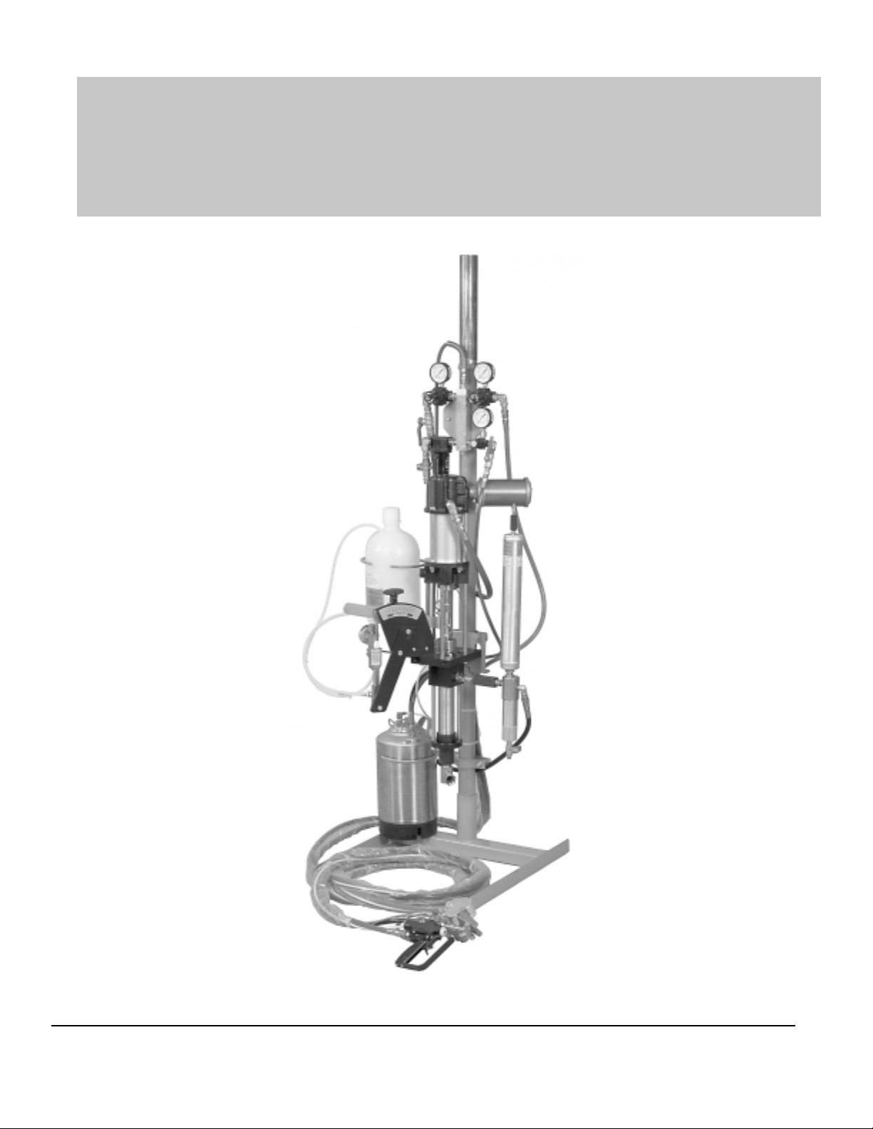
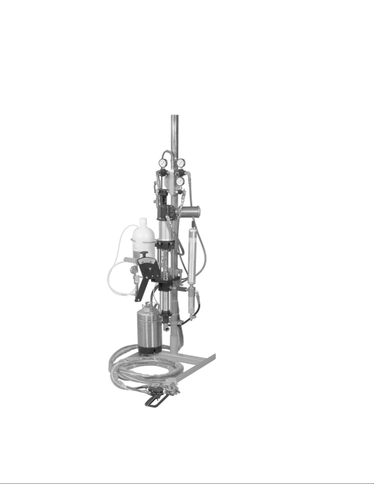
Unit Information
Power Cylinder
Metering Pump
Gun
Roving Cutter
Fluid Section
Corporate HQ & Mfg.
Phone: (727) 573-2955
Fax: (727) 571-3636
Email: info@magind.com
Web: www .magind.com
Manufacturing
Phone: (253) 854-2660 (800) 448-6035
Fax: (253) 854-1666
Email: info@venusmagnum.com
Web: www .venusmagnum.com
FRP SystemOne
© 2001 Magnum Venus Product s Manual Part No: M1100-1-1
Page 3

T able of Contents
FRP SystemOne
Operation Manual
CHAPTER 1 - QUICK LIST
Start Up
Installation & Setup
CHAPTER 2 - INST ALLATION AND SET-UP
Pre-Operation Checklist
Wetting Unit
Proper Operating Pressures
Installation
CHAPTER 3 - MAINTENANCE
CHAPTER 4 - PARTS DRAWINGS
Cart Assembly
Mounting Column Assembly
12’ Boom Assembly
Pneumatic Manifold Assembly
3-Gallon Flush T ank Assembly
FRP SystemOne
Page 4

Chapter
1
FRP SystemOne Quick List
Quick List Instructions
Start-Up Sheet
1. Check & fill solvent system
2. Check & fill resin & catalyst supply
3. Place suction wand in resin supply
4. Prime resin pump
5. Prime catalyst pump and set catalyst percentage
6. Check system for fluid leaks
7. Set air pressure to gun/chopper
8. Install turbulent mixer in mix chamber
9. Select spray tip, flow nozzle or convergence tip
10. Check chopper motor, rubber roller adjustment
1 1. Attach chute & cover
12. Adjust fan pattern
13. Adjust chop pattern
NOTE: These instructions include resin and catalyst pressurization procedures.
T o avoid equipment malfunction or possible injury , please follow these
instructions. If you have any questions, please contact our Technical Service
Department at 800-448-6035.
FRP SystemOne
1
Page 5
FRP
System
One
Pumping System
Quick List Instructions
Installation & Setup
1. Unpack unit &
components
2. Place unit & stand pipe in
base plate or portable cart (or
mount to wall with wall brackets)
Tighten bolts to secure
3. Install catalyst jug
4. Install resin surge chamber &
filter assembly
5. Install manifold air hose to power
cylinder
6. Attach hose fittings to resin
pump, catalyst pump, air &
flush tank
7. Install boom to mast
(if applicable)
8. Hang hose on boom
(if applicable)
9. Attach pickup hose
10 . Place flush tank in holder and
attach air hose from manifold
1 1. Double check all hose fittings
2
FRP SystemOne
Page 6

Chapter
2
FRP SystemOne
Installation & Set-Up
Checklist
1. Tighten all hose fittings and fluid connections to make sure they are
tight.
2. Check electrical grounds, gun to pump and pump to earth ground.
3. Check all clamp brackets, pump column, slave arm bracket, manifold
clamp, etc. T o make sure they will not move when unit is in operation.
4. Check the mounting of catalyst pump to make sure clevis pins are
secure.
5. Make sure exhaust silencer is secured to the power cylinder of the
resin pump.
6. IMPORTANT: Snug up the p acking nut at the top of the catalyst
pump Approximately ¼ turn.
7. Snug up, tighten, the resin pump packing be inserting two rods into
the holes in the oil cup at the top of the resin pump fluid section. Turn
clockwise until packing is snug.
8. Tighten the gun valve rod packing nut until it is very snug.
IMPORT ANT: Activate the gun trigger 10 - 15 times then tighten
the packing nut. Repeat this tightening procedure 3 times to make
sure the gun valve rod packing is tight.
FRP SystemOne
3
Page 7

Wetting Out Unit
Air Supply:
1. Use minimum ½” air hose supply to the system. Air requirements,
18 CFM
2. Open incoming air supply ball valve.
3. Set regulator labeled gun at 90 to 100 psi. T ighten packing nuts on
the gun and trigger the gun 15 to 20 times. Tighten p acking nuts
again and repeat gun triggering.
Priming Solvent:
1. Open solvent tank lid and fill tank ¾ full. Install lid on tank and
close the relief valve located on the top of the lid. Set flush tank
pressure at 50 to 60 psi.
2. Push the flush valve on the side of the gun block to test solvent
flush.
Priming Catalyst to Gun:
1. Tighten the catalyst packing nut ¼ turn.
2. Fill the two gallon catalyst jug ¾ full, purge the air out of the
catalyst feed line by slightly tilting the catalyst jug.
3. Lock the gun in the open position. Remove the pivot pin from
the catalyst slide arm linkage. Use the slide arm to hand prime
catalyst out to the gun until a steady stream is achieved. Do not
reinstall pivot pin at this time.
Priming Resin to Gun:
1. Insert the resin suction wand into a 55-gallon drum or resin.
2. Tighten the resin pump packing nut until tight. Fill packing nut
cavity ¾ full with suitable oil.
3. With gun locked in the open position, slowly increase resin pump
regulator pressure until pump is running at a slow but steady rate.
Allow pump to run until a fairly steady stream of resin is being
dispensed. Close the gun and flush the gun head.
4. Increase resin pump pressure to 100 psi. Allow the unit to set
under static load for 15 to 30 minutes to seat the resin packing set.
5. Clamp or tape the resin return hose coming from the bottom of the
in-line resin filter to the resin pickup wand, into the resin drum. Turn
the resin pump regulator to zero. Slowly open the ball valve at the
bottom of the resin filter to drain the fluid pressure.
4
FRP SystemOne
Page 8

Charging the Resin Surge Chamber:
1. Open ball valve below inline resin filter.
2. T o charge the resin surge chamber , use the air hose with the
female quick disconnect (charging hose) and insert over the male
quick disconnect at the top of the resin surge chamber . Push down
on female quick disconnect for 5 to 10 seconds and disengage.
3. Close ball valve below in-line resin filter.
Pressurizing Fluids:
1. Slowly increase resin pump regulator , 50 psi would be a good
starting point.
2. Pull the pivot pin using the slide arm. Use slow up and down
motion to pressurize the catalyst pump for several strokes or until
firm.
3. Pin the pivot pin into the slide arm.
Gun Set-Up:
1. Install turbulent mixer into mix chamber and install tip. For
longer turbulent mixer life, do not over tighten the nozzle cap.
2. T est the spray pattern, make pump pressure adjustment for
required resin outputs.
3. Thread either one or two strands of glass into chopper motor. Use
chopper motor pivot to adjust glass entry into resin fan. Center the
glass into the resin fan using the eccentric stud.
Start-Up Instructions
1. Removing Unit From Crate.
With the crate laying flat. Open the top panel and remove the
components as needed.
a. Cart
b. Pump and Column Assembly .
c. Boom, Hose, and Gun Assembly .
d. Resin Filter/Surge Chamber Assembly .
e. Suction Wand Assembly .
f. Component Box.
g. Catalyst Jug.
h . Solvent T ank.
FRP SystemOne
5
Page 9

2. Assemble Cart.
a. Attach Handle to Cart.
3. Assemble Pump and Column Assembly to cart.
a. Insert Column into column support hole in top of cart.
b. Orient the column until pump faces the front of the cart.
c. Tighten the lock screws to retain pump/column assemble to cart.
Lock screws are located under cart on the front side.
4. Assemble Boom, Hoses, and Gun Assembly to pump column.
a. With the boom folded, hose coiled, and gun attached as the
assembly comes out the crate. Lift the boom up and insert the
base pivot over the column.
b. With the boom installed on column. Remove the ties holding the
two sections of boom together .
c. Remove the ties that hold the gun and hoses in the coil. T ake care
not to drop the gun.
d. Remove the boom spring from the diagonal angle support at the
base of the boom.
e. Swivel the boom back over the rear of the cart (barrel location
area). Unfold the boom sections so both inner and outer sections
are straight over back of cart.
f. With the boom sections stretched out to their full reach. Attach
one end of the boom extension spring to the support chain attached at the boom knuckle.
g. While lifting the outer section of the boom upward, attach the other
end of the extension spring to the link welded to the top of the
outer boom.
NOTE
If Outer section of boom and gun hang to close the floor . Lift
the outer section of the boom again and attach the extension
spring to a new location on the support chain. Shortening the
chain will raise the outer section of the boom.
h . With the outer section of the boom supported by the spring and
chain. Fold the outer section of the boom parallel to the inner
section.
5. Assemble Resin Filter/Surge Chamber Assembly to Pump.
a. Check to make sure all Filter/Surge Chamber connections are
tight.
6
FRP SystemOne
Page 10

b. Attach the Filter/Surge Chamber Assembly to the swivel fitting
located at the outlet of the resin pump.
c. With the Filter/Surge Chamber Assembly vertical. Tighten the
fitting with a wrench until it is tight enough to prevent fluid leaks and
to support the assembly in an up right position.
6. Mount Catalyst Jug Bracket.
a. Attach the Catalyst Jug Bracket to the base of the catalyst pump
slide drive support.
b. Mount the bracket so it extends to the left side of the slide drive
support as you stand facing the end of the slide drive.
7. Mount Solvent Tank Retainer Bracket.
a. Attach the T ank Bracket to the column approximately 5 inches from
the top of the cart.
b. The bracket arm should be on the backside of the column as you
face the pump, extending to the left side of the cart.
c. Tighten the bolt s holding the yoke clamp to the bracket until the
bracket is firmly clamped to the column.
d. Remove the Solvent T ank from the carton and place into bracket.
8. Attach Catalyst Pump.
a. Mount the Catalyst Pump to the slide drive bracket using the clevis
pins and keepers provided.
b. The bottom of the catalyst pump is pinned to the lower leg of the
slide drive bracket.
c. The upper clevis, (piston rod), is pinned to the slide drive using the
hole forward of the long slot in the slide drive.
d. Hold the clevis pins in place with the wire keepers by placing them
in the holes in the clevis pins.
9. Mount Air Supply Manifold.
a. Clamp Manifold Assembly to the pump column above the power
cylinder of the resin pump.
b. Regulators and gauges should face to the pump side of the col-
umn.
c. Clamp yoke tight enough so the assembly does not move around
the column.
FRP SystemOne
7
Page 11

10.Attach Suction Wand to Resin Pump.
a. Check all fittings on the wand assembly to make sure they are
airtight.
b. Attach the wand assembly to the foot valve port of the resin pump.
11. Hose connections.
a. Connect the black resin hose from the gun to the outlet fitting on
the resin filter
b. Connect the catalyst hose from the gun to the outlet of the catalyst
pump assembly .
c. Attach the red air hose from the gun to the fitting on the regulator
labeled gun.
d. Attach the yellow poly flush hose from the gun to the outlet fitting of
the solvent tank.
e. Attach the small red air supply hose from the flush regulator to the
input fitting on the solvent tank.
f. Attach the large red air hose from the pump regulator to the power
cylinder of the resin pump.
g. Attach the ground wire from the gun to the electrical grounding lug
on the pump power head.
h . Remove the catalyst poly tubes from the component box.
i. Cut the ½ inch dia. poly line, with the clamps, to 26 inches long.
Clamp one end to the outlet of the catalyst jug and the other end to
the inlet of the catalyst pump. Make sure clamps are airtight.
j. Connect the 3/8-inch poly line to the relief valve on the catalyst
pump assembly and insert the other end into the hole in the top of
the catalyst jug.
12.Mount Exhaust Silencer to power head of resin pump.
a. Remove the exhaust deflector from the power head of the resin
pump, (4 screws). Screw silencer into the pipe threads of the
exhaust port.
NOTE
If icing of silencer becomes a problem. Remove the silencer
and replace the exhaust deflector. Noise level will be higher
with silencer removed.
8
FRP SystemOne
Page 12

Chapter
3
FRP SystemOne
Maintenance Schedule
4-Hour Oil Chopper Air Motor
For every four hours of operation, the chopper air motor should be oiled.
Push down on the quick disconnect, pull back on the clip, pull it off the bar
fitting and add one or two drops of oil for every four hours of operation.
Daily Relief Valve Check
We start to get accumulating a lot of catalyst in the hose. We want to
drain that off and see how much catalyst that we accumulate in the relief
valve hose, daily . If it’s excessive, we want to replace the ball in the relief
valve.
Daily Water Trap Check
Water traps should be drained daily . Just push the bottom button and
drain any water that may have collected in line.
Weekly Power Head Lubrication
Turn the pump regulator down to zero. Loosen the air hose fitting and add
10 to 15 drops of 90-weight non-detergent gear oil.
Weekly Fluid Section Packing Nut Check
Check the fluid section for any resin coming up through the packings into
the cavity . If you see any resin, tighten the packing nut. Add oil if needed.
Weekly Catalyst Packing Nut Check
Look for any catalyst bleeding up through the packings. If you see any
leakage, tighten the packing nut an eighth of a turn.
FRP SystemOne
9
Page 13

Weekly Gun Maintenance
Weekly maintenance on the gun includes tightening the resin and the
catalyst packing nuts.
1. Turn the pump pressure down to zero. Open up the ball valve to
relieve the fluid pressure on the resin and to release the fluid
pressure on the catalyst we’ll pull the trigger on the gun.
2. T o seat the packings, tighten both the cat alyst and the resin
packing nuts and quickly trigger the gun 10 to 15 times in rapid
succession. Repeat the process. It is very important to trigger the
gun quickly .
Surge Chamber Maintenance
For weekly cleaning of the surge chamber and filter turn the pump
regulator pressure down to zero.
1. T o relieve the fluid pressure in the resin system, open the ball
valve below the resin filter.
2. T o bleed the charge in the accumulator , insert the small diameter
rod in the charging valve on the top of the resin accumulator and
bleed the charge off. Be sure to cover the rod with a rag.
3. T o remove the resin filter , move the return hose out of our way .
Push the core out of the resin screen. Clean the screen and the
core and the inside of the bottle.
4. Unscrew the resin accumulator. Clean the accumulator and filter .
Clean the threads and white ball.
5. Inspect the oil ring and replace if cut or distorted.
6. Reinstall the core into the screen. Then reinstall the screen core
into the filter bottle. It’s very important that we use V enus white
grease on the aluminum threads before re-installing. Do not over
tighten.
7. Reinstall the resin return hose to the ball valve below the filter .
Twist until there is a snug fit. Inspect the “O” ring. Replace if
necessary.
8. Place white grease on the “O” ring and on the threads. The seat
area must be clean for the polyball to seat properly when charging
the resin accumulator. Inspect the oil ring for any split s or cuts.
Replace if necessary .
10
FRP SystemOne
Page 14

9. Place polyball on seat.
10. The surge chamber is now ready for reinstalling. Insert the “O”
ring seal in the bottom of the accumulator and lightly twist the
accumulator until it is snug.
FRP SystemOne
11
Page 15

FRP SystemOne
Part s Drawings
Chapter
4
12
FRP SystemOne
Page 16

MAGNUM VENUS PRODUCTS
FRP SystemOne
13
Page 17

14
FRP SystemOne
Page 18

MAGNUM VENUS PRODUCTS
FRP SystemOne
15
Page 19

16
FRP SystemOne
Page 20

MAGNUM VENUS PRODUCTS
FRP SystemOne
17
Page 21

18
FRP SystemOne
Page 22

MAGNUM VENUS PRODUCTS
FRP SystemOne
19
Page 23

20
FRP SystemOne
Page 24

MAGNUM VENUS PRODUCTS
FRP SystemOne
21
Page 25

22
FRP SystemOne
Page 26

FRP SystemOne
12
Page 27

FRP SystemOne
Page 28

Corporate HQ & Mfg.
Phone: (727) 573-2955
Fax: (727) 571-3636
Email: info@magind.com
Web: www.magind.com
© 2001 Magnum Venus Product s Manual Part No: M1100-1-1
FRP SystemOne
Manufacturing
Phone: (253) 854-2660 (800) 448-6035
Fax: (253) 854-1666
Email: info@venusmagnum.com
Web: www .venusmagnum.com
 Loading...