

Page 1
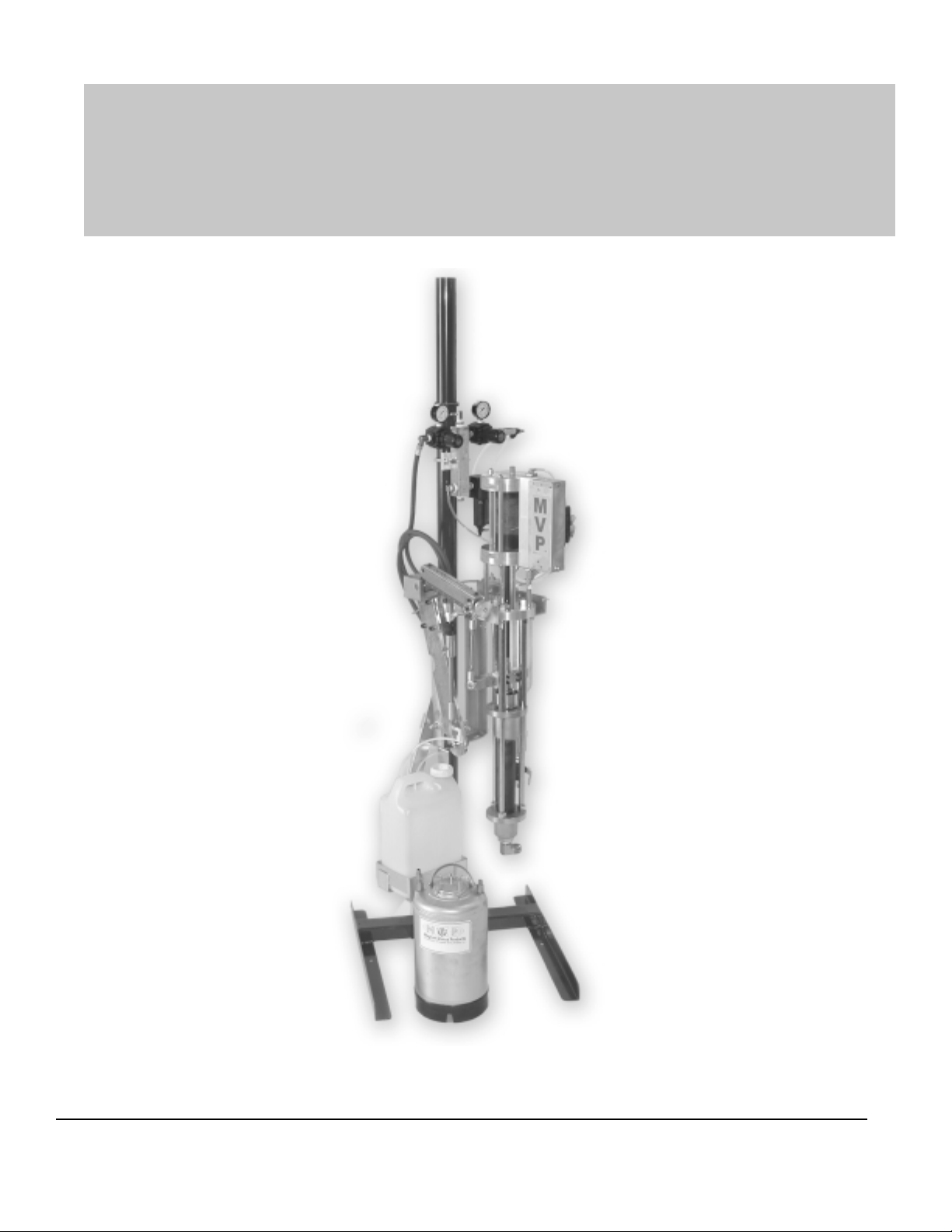
APS FIT Chop System
FIT -C-APS-3 Maintenance & Repair
MAGNUM VENUS PRODUCTS
Maintenance & Repair Manual
Part No. FIT-C-APS-3
Revision 05.14.04
Page 2

APS FIT Chop System
Maintenance & Repair Manual
Corporate HQ & Mfg.
Phone: (727) 573-2955
Fax: (727) 571-3636
E-mail: info@mvpind.com · Web: www.mvpind.com
© 2004 Magnum Venus Product s Manual Part No: FIT-C-APS-3
MVP Technology Center
Phone: (253) 854-2660 (800) 448-6035
Fax: (253) 854-1666
Page 3

Table of Content s
APS FIT Chop System
Maintenance & Repair Manual
CHAPTER 1 - BASIC TROUBLE SHOOTING GUIDES
HPC-1000 Slave Pump
Fluid Sections
Choppers
CHAPTER 2 - RC-1000 & RC-1101-1 ROVING CUTTER INSTRUCTIONS
CHAPTER 3 - ASSEMBLY PROCEDURE FOR RC-1101-1 AIR MOTOR
CHAPTER 4 - CAUTIONS & WARNINGS
CHAPTER 5 - PARTS DRAWINGS
Page 4

Chapter
Basic Trouble Shooting Guide
1
Problem
No catalyst coming from
gun.
Catalyst spitting from gun.
HPC-2000 Slave Pump
Possible Cause(s)
Ball valve open on catalyst manifold (if applicable).
Air is drawn into catalyst siphon assembly
Cracked or deteriorated (pin holes) inlet nipple at
bottom of slave pump.
Worn or cut O-ring in inlet nipple.
Improper seal around siphon hose.
Cracked or deteriorated (pin holes) catalyst siphon
hose.
Cracked or deteriorated elbow assembly on catalyst
jug assembly .
Worn or cut O-ring on elbow assembly.
Inverted washer in elbow or inlet nipple.
Recommended Solution
Be sure ball valve is fully closed.
Replace inlet nipple
Replace O-ring in inlet nipple.
Check seal and be sure hose is inserted all the
way into nipple.
Replace catalyst siphon hose.
Replace elbow assembly .
Replace O-ring.
Inspect and be certain that flat side of washer is
against the O-ring for proper sealing.
No catalyst flow on down
stroke of catalyst pump.
No catalyst flow on upstroke
of catalyst pump.
Loss of catalyst pressure.
Catalyst leaking from top of
catalyst slave pump.
Debris in lower ball and seat assembly .
Chipped or worn ball and/or seat.
Debris in ball seat assembly located at bottom of
pump shaft (commonly referred to as upper ball seat
assembly).
Chipped or worn ball and/or seat assembly .
Worn or cut O-ring on ball seat assembly located
on bottom of pump shaft (commonly referred to as
upper ball seat assembly).
Sticking catalyst pressure relief valve assembly,
located on catalyst manifold (if applicable).
Worn or cut O-rings located in top of pump.
Worn guide bushing located in upper jam nut (guide
bushing not shown on breakdown). A bent pump
shaft may cause wearing of guide bushing -- see
below.
Bent catalyst pump shaft.
Remove and clean.
Inspect and replace ball and/or seat if necessary .
Remove and clean.
Inspect and replace ball and/or seat if necessary .
Replace O-ring.
Disassemble, inspect and clean. Replace seals
if necessary .
Replace O-rings.
Replace guide bushing or whole jam nut
assembly.
Replace pump shaft.
Page 5

Fluid Sections
Problem
Fast downstroke (winking of
pattern).
Fast upstroke (winking of
pattern).
Partial dive on downstroke.
Pump stroke “chatter”.
Material leakage into
solvent cup.
Possible Cause(s)
Debris on lower ball seat.
Debris on upper ball seat.
Air siphoning.
Plugged material filter
Build up of material around pump upper packings/
seals.
Loose packings.
Worn packings.
Worn shaft.
Recommended Solution
Disassemble and clean.
Disassemble and clean.
Check for loose fittings from bottom of pump to
the end of the siphon assembly. Inspect for
kinks, cuts, loose fittings, etc. and correct as
necessary.
Disassemble and clean filter.
Disassemble and replace packings/seals.
Clean solvent cup and tighten as applicable 1/2
turn at a time. NOTE: Pressure must be off of
pump before adjusting.
Disassemble and replace upper packings.
Disassemble and replace shaft.
Intermittent stopping of
pump stroke. (Can cause
resin to continue spraying
without catalyst.)
Decrease in volume of resin
delivery .
Air lock in surge chamber. This can be caused by
the pump running when the drum is empty , or when
moving a siphon hose assembly from one drum to
another. Both of these occurences can allow air
into the system.
Clogged material filter.
Worn cylinder. Fluid is bypassing the packings
through the worn areas.
1) Reduce pump pressure to zero, disconnect
slave, slowly open vall valve on filter assembly ,
allow resing and air to escape. 2) Slowly
increase pump pressure until pump begins
stroking, after smooth flow of resin is achieved,
close valve and reconnect slave.
Periodically check drums to be sure of adequate
supply of material. Use above measures after
transfering siphon assembly from one drum to
another.
Disassemble and clean.
Disassemble and inspect cylinder for wearing
when doing repairs.
Page 6

BASIC TROUBLE SHOOTING GUIDE FOR CHOPPERS
Problem
Cutter not shutting off.
Cutter does not come on.
Glass binds up.
Possible Cause(s)
Stuck chopper poppet valve
Worn poppet valve seat.
Broken poppet valve spring.
Sticking resin needle prohibiting
actuation of poppet valve
Bent trigger
Stuck poppet valve
Obstruction in roving path.
Improper anvil sleeve to bearing tension.
Improper cutter head to anvil sleeve
tension.
Resin on roving.
Recommended Solution
Replace and lubricate O-ring on chopper
poppet valve in gun.
Replace
Replace
Replace packings
Replace
Clean, replace and lubricate seals.
Trace roving path from source to
chopper for any obstructions and fix as
necessary.
Adjust as necessary .
Adjust as necessary .
Clean as necessary , keep roving away
from resin and overspray .
Improper chop length.
Cutter running too slow.
Worn cutter wheel.
Open slots in cutter wheel.
Worn or broken blades.
Worn or misadjusted anvil sleeve.
Worn blades
Tension on anvil sleeve to bearing or
cutter head too tight.
Low air volume.
Worn air motor
“Dry” air motor
Chopper poppet in gun sticking.
Replace
Be sure all blade slots are filled with a
retainer bar and spacer (whether a blade
is inserted or not).
Replace
Replace or adjust properly
Replace blades
Adjust as necessary .
Inspect hoses for kinks or cuts.
Inspect primary air line to system for
proper diameter and volume. Call MVP
to discuss.
Replace or rebuild.
Oil air motor daily with 3-5 drops of MVP
AMO air motor oil.
Remove, replace O-rings and lubricate.
(Check for broken poppet spring and
replace if necessary .)
Cutter not running.
Chopper poppet stuck in closed position.
Air motor “locked up”.
Clean, replace O-rings if necessary and
lubricate.
Rebuild or replace air motor.
Page 7

RC-1000 & RC-110101
Chapter
Roving Cutter Instructions
2
RC-1000
The RC-1000 cutter was designed to cut glass roving into short lengths of 1/2” to 4”, and dispense it into a
resin fan. When properly adjusted, the chopped glass will be spread out evenly from edge to edge of the
resin pattern. Also, the glass/resin mixture on the part will need a minimum amount of rolling.
AIR REQUIREMENTS
The RC-1000 requires 15 CFM of clean, filtered air at a minimum of 90 PSI to operate efficiently. The air
supply hose must have a minimum 5/16” inside diameter for a 25-foot hose. A longer hose may need a
larger inside diameter. Lower air pressures or smaller hose could result in poor operation.
OPERATION
To introduce roving to the cutter, double up the end of roving and insert into one of the three holes in the
feed bar on top of the cutter. The motor control knob on the bottom of the manifold assembly should be
opened about a full turn out. The blower control knob on the side should be about 1/2 turn out at the
beginneing. Pull trigger and glass will be dispensed into the resin fan. The blower control keeps air moving through the chopper cover to help keep it from plugging. By opening or closing the motor control knob,
the glass output will increase or decrease accordingly. Adjust both motor control and blower control to
produce the desired output and pattern.
ADJUSTMENTS
Idler Bearing: With glass roving in place, idler should hold glass against the anvil sleeve. Excessive
tension may cause the glass to wrap around the idler bearing. Adjustments are accomplished by loosening the idler bolt, rotating the eccentric nut and then retightening.
Air Motor: The air motor on your cutter is precision built and with proper care, under normal operation,
will last hundreds of hours of continuous use. It is important that this motor be lubricated at the end of
each working shift. Lubrication is best accomplished by removing the motor speed control valve, and
inserting 8 drops of a lightweight oil. Replace needle valve and run the cutter for approximately five seconds. It is not necessary to cut glass curing this time. The clearances of this motor are extremely critical.
For this reason, it is advisable that the motor be sent to an authorized distributor for repair. The warranty
is void if this motor is opened by any except factory-authorized repair centers.
Page 8
Cutter Adjustment: The glass should enter the resin fan as soon as possible without excessive glass
fallout. Normally, if the glass enters the resin when the glass pattern and resin pattern are about the same
width it will give the best resluts. This is achieved by centering the glass pattern by moving the cutter left or
right -- forward or backward.
DISASSEMBLY OF CUTTER
Remove the air motor and manifold assembly by first removing the snap ring and anvil sleeve. Then loosen
screw and the motor and manifold will slide out of the backplate. DO NOT USE A HAMMER TO FORCE
MOTOR OUT. If frozen, a slight pressure with a screwdriver between the motor and backplate will do fine.
To remove blower and motor control manifold will then drop free from the air motor. Cutterhead and idler
bearing can be taken off of the backplate by unscrewing their hold down bolts from the corresponding eccentric nuts.
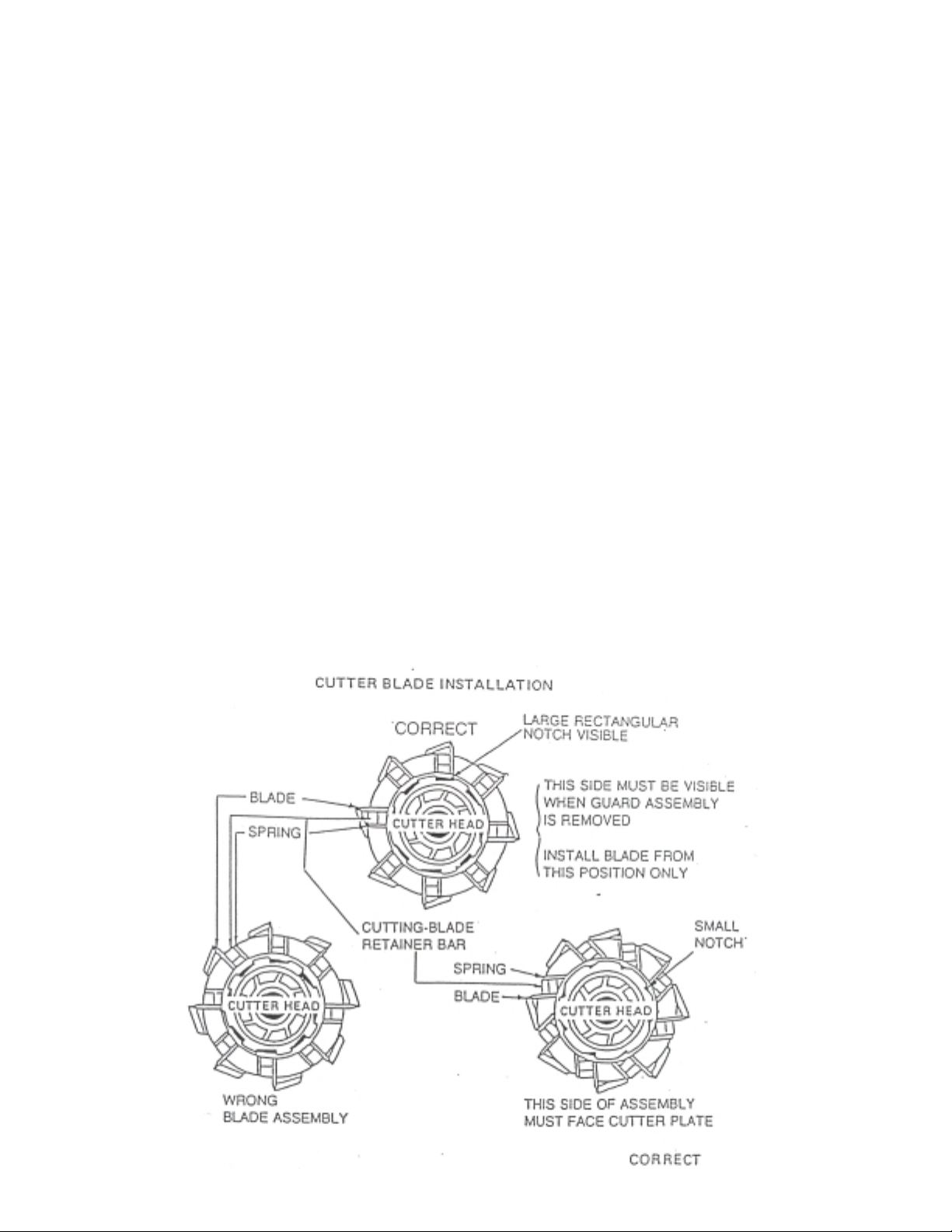
BLADE REPLACEMENT
The cutter comes from the factory set to cut 1-inch lengths of glass rovings by using for evenly
spaced blades inserted in the cutting head assembly. There are slots ever 1/2-inch on the cutting
head. By inserting or removing blades you can vary the length of cut for different applications.
However, the 1-inch length is the most popular length used.
To replace cutting blades, pry out the blad retainer and spring using a small screwdriver. The old
blade will fall free of the slot when this is done. When inserting the new blades, be sure that they are
on the front side of the slot, then insert retaining bar. Finally, insert the retaining spring. This is
accomplished by using a pair of needle nose pliers.
WARNING:
Use caution to prevent cuts as these blades are razor sharp!
Page 9

Chapter
RC-1101-1 Air Motor
3
RC-1101-1 ASSEMBLY OF AIR MOTOR
1. Remove Burrs: With fine file or emery cloth.
2. End Clearance: Average end clearance .0015” to .002”. To get end clearance take micrometer
reading of body minust micrometer readin gof rotor assembly, add gaskets (if needed) to get required clearance, assemble air motor with gaskets on both drive and dead end.
3. Select End Plate (Drive): End plate with no threads in hub.
4. Assemble Rotor and End Plate (Drive): Position bearing on shaft and with bearing pusher, press
bearing into end plate hub.
5. Assemble Bearing: Position bearing on shaft and with bearing pusher, press bearing into end
plate hub.
6. Position Rotor Assembly: Using inner-race tapper, tap inner-race of bearing until slight drag
between end plate and rotor assembly.
7. Position Body: Long port is exhaust, small hole drilled through body, intersecting hole drilled from
top is intake. For clockwise rotation small hole is on your right. For counterclockwise rotation small
hole is on your left.
8. Assemble Gasket (Drive): Take approximate 1/2 total gasket needed for end clearance. As-
semble on drive end, hold in position with few drops of oil, punch hole in gasket over air passage.
9. Assemble End Plate, Rotor and Body: Position end plate and rotor in body, over gasket, assemble screws, snug, oil hole in end plate to top of body.
10. Top Clearance: Place parts in align-up fixture, resting on hub. Using a .0015” shim, have a snug
fit between tightest segment and top of body.
11. Assemble Vanes: With angle on vane toward shaft.
12. Assemble Gasket (Dead): Take balance of fasket from overall clearance, hold in position with few
drops of oil. Punch hole in gasket over air passage.
Page 10

13. Select End Plate (Dead): End plate with threads in hub. When assembled, kidney ports in end
plates must be on intake side.
14. Assemble End Plate (Dead): Position end plate over shaft, place on body, assemble screws, snug,
loosen one turn.
15. Assemble Bearing: Place bearing on shaft, using bearing pusher, position bearing in end plate.
16. Check Movement of End Plate: End plate must move back and forth. If no movement, top clear-
ance is not in center-reset top clearance. If moves, snug screws, remove from fixture, tighten screws.
17. Adjust End Clearance: Rotor is snug against drive end plate. Using inner-race tapper, tap innerrace of bearing (very lightly) in dead end plate until rotor is free. Push and turn, pull and turn, until no
drag on either end plate. For finer adjustment start air motor, adjust by sound.
18. Assemble Seal: Press into end plate, small amount of grease on seal.
19. Assemble End Cap: Into end plate.
20. T est Air Motor: For normal duties.
Page 11

Chapter
Cautions and Warnings
4
AIRLESS EQUIPMENT SAFETY
Injection Hazard
• DO NOT POINT THE GUN AT ANY PERSON
• NEVER LOOK AT THE GUN FROM THE FRONT (NOZZLE END)
• NEVER trigger an airless gun while it is aimed at a person. The hydraulic pressure may inject fluid into
the flesh, causing injury or death. If the fluid penetrates the skill it WILL cause serious injury. Clothing,
such as gloves will NOT provide protection. The system is capable of fluid pressure high enough to
cause a LETHAL INJECTION.
• TREA T THE APPLICATOR AS YOU WOULD A LOADED WEAPON.
Before applying pressure to the system, ALWAYS:
• Follow the manufacturer’s operating instructions and maximum pressure recommendations.
• Secure the trigger in the OFF position and check all pressure connections.
• Use grounded, high pressure fluid lines.
• Check that the pump is properly grounded.
Before disassembly of ANY part of the pressure system (including the applicator or its nozzle) ALWAYS:
• Shut the pump OFF.
• Discharge the residual fluid and pressure from the applicator.
• Secure the trigger in the OFF position.
Follow these same three procedures anytime that operation is discontinued.
Do NOT undertake any of the following until pressure is relieved from the entire system:
• Loosen or remove the nozzle.
• Disassemble any part of the applicator.
• Loosen or disconnect any fluid line fittings.
• Disassemble any part of the pump.
Be sure that the power to the pump is OFF before undertaking ANY repair, maintenance or adjustment.
If it is necessary to adjust or clean the nozzle on site, be sure that it is aimed away from all personnel so
that it may discharge safely if there is residual pressure in the system.
Do NOT use any replacement part that does not meet the manufacturer’s specifications.
Page 12

Correct packing or valve seal leaks IMMEDIATELY.
Frequently check the condition of all pressurized components, especailly fluid lines. Replace worn lines and
parts before they fail.
If nozzle clogging occurs frequently, use a fluid filter with proper mesh size.
PUMPING SYSTEM SAFETY INSTRUCTIONS
Use MVP replacement parts to assure compatible pressure rating. Read ALL warning and safety
instructions carefully before operation of this unit. Heed all warnings.
WARNING
Never allow any part of the human body to come in front of, or in direct contact with, the material outlet.
Accidental operation of the pump could cause an injection into the flesh. If injection occurs, medical aid
must be immediately obtained from a physician.
Component Rupture: This unit is capable of producing high fluid pressure as stated on the pump model
plate. To avoid component rupture, and possible injury, do not exceed 75 cycles per minute or operate at an
air inlet pressure greater than 150 PSI (10 bar).
Servicing: Before servicing, cleaning or removing any component, ALWA YS disconnect or shut off power
source and carefully relieve all fluid pressure from the system.
CAUTION: When pumping, flushing or recirculating volatile solvents, the area must be adequately
ventilated.
CAUTION: Materials and solvent being pumped must be compatible with the parts of the pump that
becomes wetted when in contact with material or solvent. Wetted parts consist of the following: stainless
steel, copper, brass, steel, gray iron, leather, teflon and vellumoid.
CAUTION: Keep solvents away from heat, sparks and open flames. Keep containers closed when not in
use.
Prevent Static Sparking: If static sparking occurs, fire or explosion could result. The pump, dispensing
valve, and containers must be grounded when handling flammable fluids shuch as solvents, paints,
lacquers, etc., and wherever discharge of static electricity is a hazard.
Use grounded hoses (static wire) and be sure the object being serviced is grounded if it can produce a static
charge.
Continuity (a good static wire connection) of a hose can be checked by using an ohmmeter. Place one
prove on one hose fitting and the other probe on the other hose fitting, continuity or proper grounding
through hose is good when a reading is obtained on the ohmmeter.
Air and Lube Requirements: Excessive air pressure will shorten the life of the pump. Do not operate pump
above recommended maximum air pressure. If necessary, an air regulator should be installed to maintain
the desired pressure when the pump is in operation.
Page 13

Filtered and oiled air will allow the pump to operate more efficiently and yield a longer life to operating parts
and mechanisms.
Keep oiler supplied with MVP Pump Motor Oil. A filter capable of filtering particles larger than 50 microns
should be used with an oiler.
Maintenance: If the pump is to be inoperative for a lengthy period of time (even for a few hours) disconnect
air and relieve all pressure from system.
Periodically flush pump with a solvent that is compatible with the material being pumped. Pour a little throat
seal lubricant into the solvent cup to keep upper packings pliable and to keep material drag-thru soft.
Material drag-thru that is allowed to harden, will scour the piston rod. This will create excessive leakage and
rapid packing wear.
Disassembly should be done on a clean work bench with clean cloths to keep parts clean.
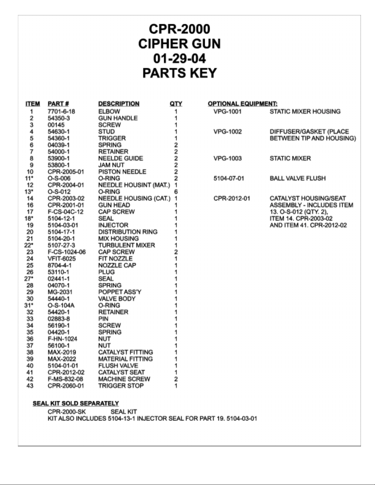
If replacement parts are necessary, consult Parts List for identification.
Before assembling, lubricate parts where required. When assembling O-rings, or parts adjacent to O-rings,
care must be excercised to prevent damage to O-ring and O-ring groove surfaces.
If you have any questions about safety or procedures, contact your Magnum Venus Products’
representative.
Page 14

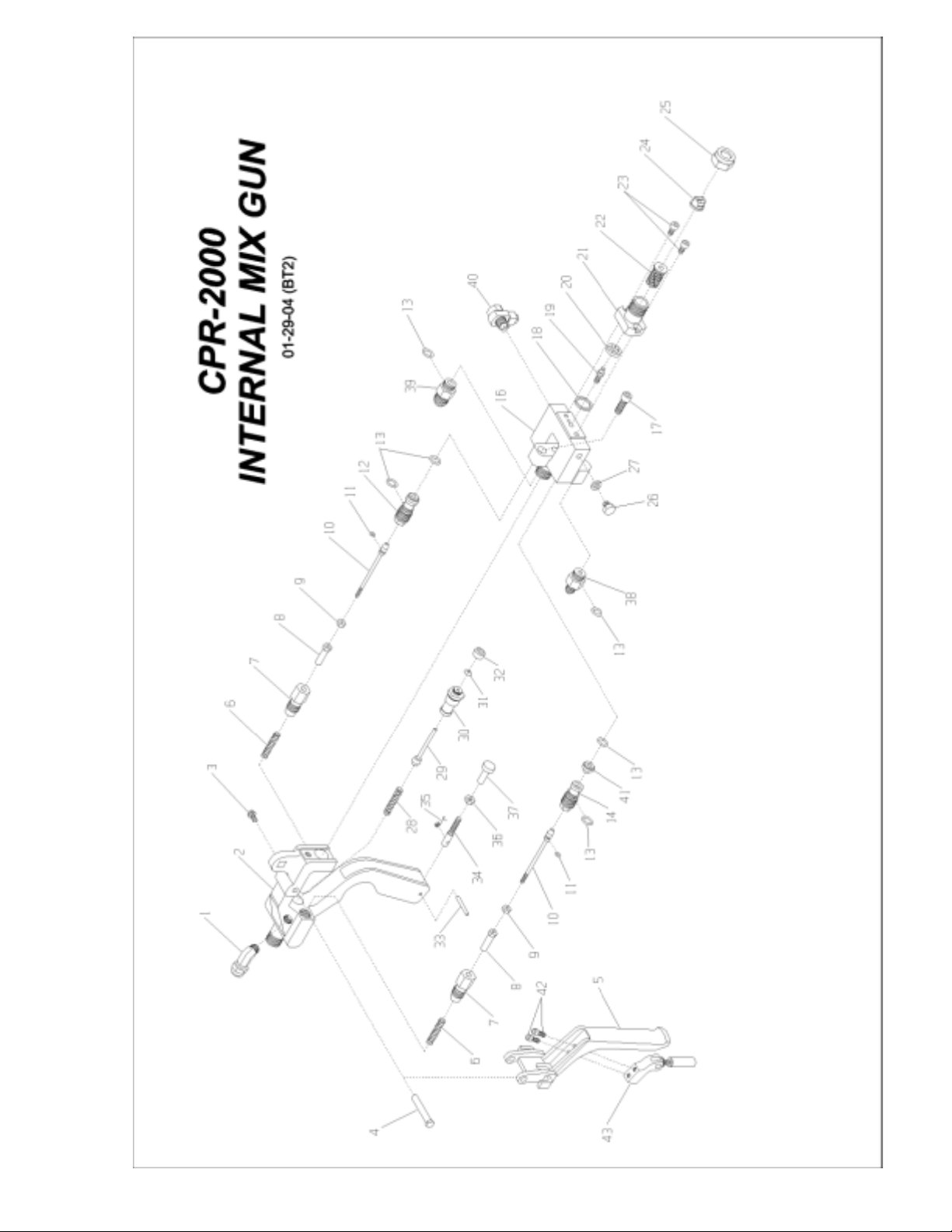
Parts Drawings
Chapter
5
Page 15
Page 16
Page 17
Page 18

Page 19

Page 20

Page 21

Page 22

Page 23

Page 24

Page 25

Page 26

Page 27

Page 28

Page 29

Page 30

Page 31

Page 32

Page 33

Page 34

Page 35

Page 36

Page 37

Page 38

Page 39

Page 40

Page 41

Page 42

Page 43

Page 44

Page 45

Page 46

Page 47

Page 48

Page 49

Page 50

Page 51

Page 52

Page 53

Page 54

Corporate HQ & Mfg.
Phone: (727) 573-2955
Fax: (727) 571-3636
E-mail: info@mvpind.com · Web: www.mvpind.com
© 2004 Magnum Venus Products Manual Part No: FIT-C-APS-3
MVP Technology Center
Phone: (253) 854-2660 (800) 448-6035
Fax: (253) 854-1666
 Loading...