

Page 1
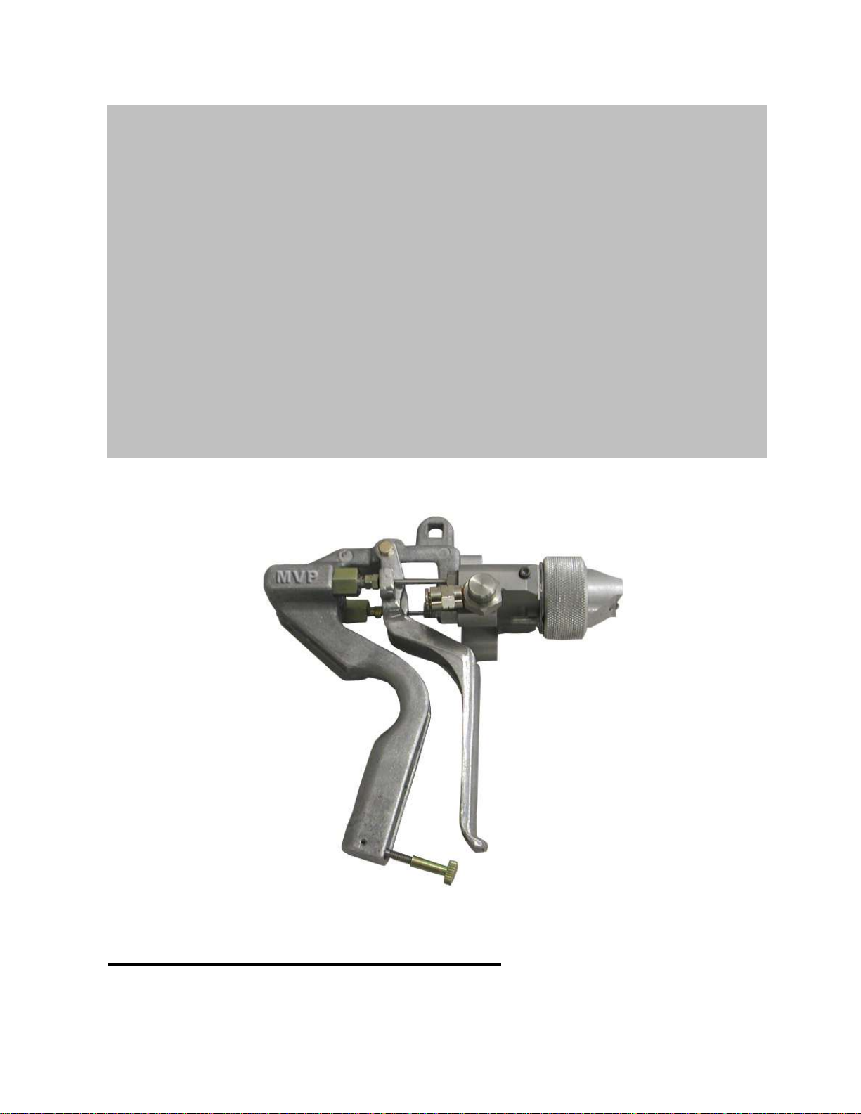
EXTERNAL MIX
GEL COAT GUN
Repair Manual
EMG-1000 & EMG-1500
MAGNUM VENUS PLASTECH
GEL COAT GUN REPAIR MANUAL Rev. 04/04/2007
Page 2

Page 3

EMG-1000 & EMG-1500 Gel Coat Gun Manual
TABLE OF CONTAINS:
WARNING AND SAFETY INFORMATION
CHAPTER 1 – GUN DISASSEMBLY AND ASSEMBLY
CHAPTER 2 – GUN BLOCK AND HANDLE ASSEMBLY
CHAPTER 3 – GUN ADJUSTMENT AND START UP
CHAPTER 4 – TROUBLESHOOTING
CHAPTER 5 – PARTS DRAWINGS
Page 4

AIRLESS EQUIPMENT SAFETY
Injection Hazard
• DO NOT POINT THE GUN AT ANY PERSON
• NEVER LOOK AT THE GUN FROM THE FRONT (NOZZLE END)
• NEVER trigger an airless gun while it is aimed at a person. The hydraulic pressure
may inject fluid into the flesh, causing injury or death. If the fluid penetrates the skin it
WILL cause serious injury. Clothing, such as gloves will NOT provide protection. The
system is capable of fluid pressure high enough to cause a LETHAL INJECTION.
• TREAT THE APPLICATOR AS YOU WOULD A LOADED WEAPON.
Before applying pressure to the system, ALWAYS:
• Follow the manufacturer’s operating instructions and maximum pressure
recommendations.
• Secure the trigger in the OFF position and check all pressure connections.
• Use grounded, high pressure fluid lines.
• Check that the pump is properly grounded.
Before disassembly of ANY part of the pressure system (including the applicator or its
nozzle) ALWAYS:
• Shut the pump OFF.
• Discharge the residual fluid and pressure from the applicator.
• Secure the trigger in the OFF position.
Follow these same three procedures anytime that operation is discontinued.
Do NOT undertake any of the following until pressure is relieved from the entire system:
• Loosen or remove the nozzle.
• Disassemble any part of the applicator.
• Loosen or disconnect any fluid line fittings.
• Disassemble any part of the pump.
Page 5

Be sure that the power to the pump is OFF before undertaking ANY repair, maintenance
or adjustment.
If it is necessary to adjust or clean the nozzle on site, be sure that it is aimed away from
all personnel so that it may discharge safely if there is residual pressure in the system.
Do NOT use any replacement part that does not meet the manufacturer’s specifications.
Correct packing or valve seal leaks IMMEDIATELY.
Frequently check the condition of all pressurized components, especially fluid lines.
Replace worn lines and parts before they fail.
If nozzle clogging occurs frequently, use a fluid filter with proper mesh size.
Page 6

PUMPING SYSTEM SAFETY INSTRUCTIONS
Use MVP replacement parts to assure compatible pressure rating. Read ALL warning
and safety instructions carefully before operation of this unit. Heed all warnings.
WARNING: Never allow any part of the human body to come in front of, or in
direct contact with, the material outlet. Accidental operation of the pump could cause an
injection into the flesh. If injection occurs, medical aid must be immediately obtained
from a physician.
Component Rupture: This unit is capable of producing high fluid pressure as stated on
the pump model plate. To avoid component rupture, and possible injury, do not exceed
75 cycles per minute or operate at an air inlet pressure greater than 150 PSI (10 bar).
Servicing: Before servicing, cleaning or removing any component, ALWAYS
disconnect or shut off power source and carefully relieve all fluid pressure from the
system.
CAUTION: When pumping, flushing or recirculating volatile solvents, the area must
be adequately ventilated.
CAUTION: Materials and solvent being pumped must be compatible with the parts of
the pump that becomes wetted when in contact with material or solvent. Wetted parts
consist of the following: stainless steel, copper, brass, steel, gray iron, leather, Teflon
and Velluloid.
CAUTION: Keep solvents away from heat, sparks and open flames. Keep containers
closed when not in use.
Prevent Static Sparking: If static sparking occurs, fire or explosion could result. The
pump, dispensing valve, and containers must be grounded when handling flammable
fluids such as solvents, paints, lacquers, etc., and wherever discharge of static
electricity is a hazard.
Use grounded hoses (static wire) and be sure the object being serviced is grounded if it
can produce a static charge.
Continuity (a good static wire connection) of a hose can be checked by using an
ohmmeter. Place one probe on one hose fitting and the other probe on the other hose
fitting, continuity or proper grounding through hose is good when a reading is obtained
on the ohmmeter.
Air and Lube Requirements: Excessive air pressure will shorten the life of the pump.
Do not operate pump above recommended maximum air pressure. If necessary, an air
regulator should be installed to maintain the desired pressure when the pump is in
operation.
Page 7

Filtered air will allow the pump to operate more efficiently and yield a longer life to
operating parts and mechanisms.
A filter capable of filtering particles larger than 50 microns should be used.
Maintenance: If the pump is to be inoperative for a lengthy period of time (even for a
few hours) disconnect air and relieve all pressure from system.
Periodically flush pump with a solvent that is compatible with the material being
pumped. Pour a little throat seal lubricant into the solvent cup to keep upper packings
pliable and to keep material drag-thru soft. Material drag-thru that is allowed to harden,
will score the piston rod. This will create excessive leakage and rapid packing wear.
Disassembly should be done on a clean work bench with clean cloths to keep parts
clean.
If replacement parts are necessary, consult Parts List for identification.
Before assembling, lubricate parts where required. When assembling O-rings, or parts
adjacent to O-rings, care must be exercised to prevent damage to O-ring and O-ring
groove surfaces.
If you have any questions about safety or procedures, contact your Magnum Venus
Plastech’ representative.
CAUTION: Materials and solvent being pumped must be compatible with the parts of
the pump that becomes wetted when in contact with material or solvent. Wetted parts
consist of the following: stainless steel, copper, brass, steel, gray iron, leather, Teflon
and Vellumoid.
CAUTION: Keep solvents away from heat, sparks and open flames. Keep containers
closed when not in use.
Page 8

Important safety information –
HAZARD
CAUSE
SAFEGUARD
Fire
Solvent and coatings can be highly
flammable or combustible, especially
when sprayed.
Adequate exhaust must be provided to keep
air free of accumulations of flammable
vapors.
Smoking must NEVER be allowed in the
spray area.
Fire extinguishing equipment must be present
in the spray area.
Solvent
During cleaning and flushing, solvents
can be forcefully expelled from fluid
and air passages. Some solvents can
cause eye injury.
Wear eye protection.
Inhaling Toxic
Substances
Certain materials may be harmful if
inhaled or if there is contact with skin.
Follow the requirements of the Material
Safety Data Sheet supplied by your coating
material manufacturer.
Adequate exhaust must be provided to keep
the air free of accumulations of toxic
materials.
Explosion Hazard –
Incompatible
Materials
Halogenated hydrocarbon solvents
(for example; Methylene chloride and
1,1,1-Thrichloroethane) can
chemically react with aluminum. The
chemical reaction caused by these
solvents reacting with aluminum can
become violent and lead to an
equipment explosion.
Guns with Stainless Steel internal
passageways may be used with these
solvents. However, aluminum is widely used
in other spray application equipment – such
as material pumps, regulators, valves & cups.
Check all equipment items before use and
make sure they can also be used safely with
these solvents. Read the label or data sheet
for the material you intend to spray. If in
doubt as to whether or not a coating or
cleaning material is compatible, contact your
material supplier.
General Safety
Improper operation or maintenance of
equipment.
Operators should be given adequate training
in the safe use & maintenance of the
equipment (in accordance with the
requirement of NFPA-33 Chapter 15). Users
must comply with all local & national codes of
practice and insurance company
requirements governing ventilation, fire
precaution, operation, maintenance and
house keeping. These are OSHA Section
1910.94 and 1910.107 and NFPA-33. Risk is
reduced by avoiding or lessening factors 1-7.
All equipment must be grounded for static electricity in accordance with NFPA-77. Be sure to relieve all
pressure from system before performing any maintenance. Spray equipment shall be used in spray
areas in accordance with NFPA, OSHA and Country/State/local requirements.
The below potential hazards may cause an injury or loss of life
Page 9

WARNING
Static Spark
Can Cause explosion resulting severe injury
or death.
Ground pump and pumping
system
Injection Hazard
Any material injected into flesh can cause
severe injury or death.
Keep body parts away from
outlet device. If an injection
occurs, immediately obtain
medical attention.
Hazardous
pressure
Sudden pressure release can cause severe
injury or death.
Pumping system can remain
pressurized when pump is not
operating.
Excessive inlet
pressure
Can cause severe injury or death
Do not exceed the maximum inlet
pressure as stated on the model
plate.
INSPECTION AND MAINTENANCE OF UNIT
1) Check solvent cup to be sure it is 1/3 full.
2) Check catalyst and material levels.
3) Inspect material spray tip and o-ring. Replace if necessary.
4) Inspect catalyst tip assembly and o-rings. Replace if necessary.
5) Inspect tip pin o-rings on front of gun head and replace if nicked or worn.
6) Assemble catalyst tip and material tip onto gun.
7) Lubricate threads on retaining ring and assembly onto gun.
8) Inspect hose assemblies and connections for leaks and wear and tear. Replace if
necessary. Do not wait until hose is so worn that it may burst.
9) Check roving quantity (if applicable).
10) Inspect and replace if necessary:
a) Chopper Blades
b) Anvil Sleeve
c) Cutter Head Bearing
d) Idler Bearing
11) Inspect and adjust if necessary:
a) Cutter head to Anvil Sleeve tension
b) Idler Bearing to Anvil Sleeve tension
c) Check Chopper position for most efficient disbursement of chop into spray
pattern.
12) Oil Cutter assembly Air Motor with Magnum Air Motor Oil as necessary (normally 2 –
3 drops daily, depending on usage).
Page 10

PREPARATION AND PRIMING OF “NEW” SYSTEM
1. Be sure all air regulators are turned completely to the left, shutting off air to the
components.
2. Slowly open main air.
3. Prime empty catalyst line:
a. Disengage catalyst pump
b. Open ball valve on catalyst manifold (if applicable)
c. Eliminate air pockets by manually hand pumping the catalyst 5-10 short
strokes (2-3 in.). After eliminating air pockets, and while continuing to
hand pump, close ball valve on catalyst manifold.
d. Pull and hold trigger on gun while hand pumping catalyst pump with short
strokes until there is a solid, steady catalyst flow from the head of the gun.
This will ensure that all air is purged from the line. Release trigger.
e. Continue to hand pump the catalyst with short strokes until catalyst is fully
primed and pressurized (generally within 5 additional strokes or less).
NOTE: Do NOT engage slave pump until material pump has been primed.
4. Material Pump: (be sure catalyst pump is disengaged) Place a container or
bucket under ball valve located at the bottom of the resin filter assembly to catch
material while priming. Open ball valve. Slowly bring up pressure on material
pump regulator just enough to allow pump to stroke up and down evenly. After a
smooth flow of material is flowing from the valve, turn regulator off and close the
valve.
5. Pull trigger on gun and allow gun to hang above waste container. Slowly bring up
pump pressure again to allow material to flow out of gun. Release trigger to close
gun. Pump will cycle until it is fully primed and then will stall out.
6. Engage slave pump.
Page 11

PREPARATION AND PRIMING OF PREVIOUSLY USED
(shut down) SYSTEM
1. Slowly open main air.
2. Material Pump: (be sure catalyst pump is disengaged) Place a container or
bucket under ball valve located at the bottom of the resin filter assembly to catch
material while priming. Open ball valve. Slowly bring up pressure on material
pump regulator just enough to allow pump to stroke up and down evenly. After a
smooth flow of material is flowing from the valve, turn regulator off and close the
valve.
3. Catalyst Slave Pump:
a. Disengage slave pump.
b. Open ball valve of catalyst manifold (if applicable).
c. Eliminate all air pockets in feed lines by manually pumping catalyst pump
until catalyst exits ball valve. Close ball valve.
e. Open gun by pulling trigger and continue hand pumping until catalyst exits
gun.
f. Leave Catalyst Pump disengaged.
4. Pull trigger on gun and allow gun to hang above waste container. Slowly bring up
pump pressure again to allow material to flow out of gun. Release trigger to close
gun. Pump will cycle until it is fully primed and then will stall out.
6. Engage slave pump.
Page 12

SHUT DOWN PROCEDURES FOR SPRAY EQUIPMENT
1. Trigger gun until pump shaft is in the full down position (at bottom of stroke position).
2. Engage gun trigger lock.
3. Relieving pressures:
a. Close main air valve to system.
b. Purge excess air from system by relieving air from the bottom of the air
filter or water trap.
c. Catalyst pressure: “Dump” or relieve catalyst pressure at catalyst
manifold (if applicable) by opening catalyst ball valve. Pressure will
immediately be relieved. Close the ball valve at once to avoid draining of
catalyst from catalyst line.
d. Material pressure: Place a container under material ball valve at bottom of
fluid filter assembly to catch material flow when relieving pressure.
Slowly open material ball valve to relieve pressure.
Remember - the pump is under extreme pressure. Use the utmost caution when
opening the valve to avoid injury or being sprayed with material. Once material
pressure is relieved, close ball valve.
5. Remove catalyst and material tip assemblies from head of gun and clean
thoroughly.
6. Thoroughly clean the front of gun head.
7. Inspect entire gun and equipment for over spray and clean.
System is now “shut-down” and ready for the next start-up
Important Notes:
Proper cleanliness habits of your spray equipment go a long way in keeping
down unnecessary maintenance and repair costs.
Page 13

AIR PRESSURES
1. Air requirement recommendations:
a. A minimum of 100 psi on main air.
b. 20 - 30 CFM for chopper systems
2. Material pump: 30 - 50 psi
TESTING SPRAY PATTERN
1. Testing of your spray pattern should be performed away from original part. Use
paper or cardboard to check the following: (see “Testing & Adjusting Manual”)
2. Spray pattern width and output
3. Catalyzation
4. Spray pattern definition (fingers and tails):
5. Adjust as necessary with the “MVP Air Assist” adjustment screw to give the finest
pattern available by eliminating fingers and tails.
After completion of the above procedures, you may now confidently use your
MVP system
Page 14

CHAPTER
1
EMG-1000 & EMG-1500 Gel Coat Gun
Disassembly
WARNING: Always remove fluid pressures before working on the unit.
WARNING: Be careful not to bend the catalyst and resin needles.
Initial Disassembly . . .
1. Remove Catalyst, Resin and Air pressure from system before disassembly.
2. Remove Catalyst, Resin and Air lines from the Gun Block Assembly.
3. Remove Screw (00145) from Trigger Stud (54630-1).
4. Remove Trigger Stud (54630-1) from Gun Handle and Trigger (MAX-2040).
5. Remove Trigger (MAX-2040) from gun assembly.
6. To remove the Gun Block Assembly (EMG-1001-01) from Gun Handle remove
Cap Screw (F-CS-04C-12) located at the back center, just above the Gun Block
Assembly.
You now have two components, the Gun Block Assembly and Gun Handle Assembly.
Page 15

Gun Handle Disassembly
1. Remove Spring Retainers (54000-1) and Springs (04039-1) from handle.
PROCEDURES 1 -4 BELOW FOR EMG-1500 ONLY –
1. Remove Valve Body Assembly (54440-1) from Handle (54350-3).
2. Remove Spring (04070-1) and Poppet Assembly (54501-1).
3. Unscrew Retainer (54420-1) from Valve Body (54440-1)
4. Remove O-Ring (O-S-104A)
Gun Handle Assembly
1. Apply lubricant to Springs (04039-1) and insert into Gun Handle.
2. Thread Spring Retainers (54000-1) over Springs (04039-1) into Gun Handle.
PROCEDURES 1-4 BELOW FOR EMG-1500 ONLY –
1. Slide Spring (04070-1) onto the end of the Poppet Assembly (54501-1)
2. Insert Poppet Assembly (54501-1) into Valve Body (54440-1)
3. Slide O-ring (O-S-104A) over Poppet Assembly (54501-1) and retain with
Packing Retainer (54420-1)
4. Screw Assembled Valve Body (54440-1) into the Gun Handle (54350-3)
Page 16

Gun Head Disassembly
1. Remove the Retaining Ring (VPA-1003) from the front of the Gun.
2. Remove the Catalyst Tip and Nozzle from the front of the Gun.
3. If necessary remove the Thread Adapter (EMG-1002-01) by loosening the two
Screws (F-HBCS-832-06).
4. Remove the O-ring (O-S-006) from the front of the Thread Adapter (EMG-1002-01).
5. Remove Needle Guide (53900-1) and Jam Nut (53800-1) from Catalyst Piston
Needle (DMX-3008-01)
6. Pull Catalyst Needle (CPR-2005-01) from the Needle Housings (CPR-2003-02).
7. Remove O-ring (O-S-006) from the end of the Catalyst Needle (CPR-2005-01).
8. Unscrew Catalyst Needle Housing (CPR-2003-02) from Gun Head (EMG-1001-01).
9. Remove Catalyst Seat (CPR-2012-02) and O-ring (O-S-012) from the gun block
10. Unscrew Resin Seal Housing (MAX-2013) from Gun Head (EMG-1001-01)
11. Remove Needle Guide (53900-1) and Jam Nut (53800-1) from Needle (MAX-
2010-01)
12. Unscrew Packing Nut (MG-1022) from Seal Housing (MAX-2013)
13. Pull Needle (MAX-2010-01) from Seal Housing (MAX-2013)
14. Remove Packing Seal (MAX-2008) and Seal Retainer (MAX-2009) from Seal
Housing (MAX-2013)
15. Unscrew Carbide Seat (MAX-2011-01) from Gun Head (EMG-1001-01) using a
9/64 hex Allen wrench.
16. Remove O-ring (O-T-010) from the gun block
17. Remove Catalyst fitting / Check Valve from the gun block
18. Remove Material Fitting (55500-1) from the gun block.
19. Remove Check Valve Cap (EMG-1010) and Push Fitting (06977) from the Check
Valve Body (EMG-1008).
20. Remove the Check Valve Body assembly (EMG-1008) from the gun block.
Page 17

Check Valve Body Disassembly
1. Using a wrench or vice hold the hex of the Check Valve Stem (EMG-1007) and
using a flat blade screw driver remove the Check Valve Nut (EMG-1009).
2. Remove the Check Valve Stem (EMG-1007) and Check Valve Spring (EMG-
1001) from the Check Valve Body (EMG-1008).
Check Valve Body Assembly
1. Replace O-ring (O-S-007) on Check Valve Stem (EMG-1007).
2. Install the Check Valve Stem (EMG-1007) into the front of the Check Valve Body
(EMG-1008).
3. Install the Check Valve Spring into the back of the Check Valve Body (EMG-
1008).
4. Using your finger hold the hex of the Check Valve Stem (EMG-1007) and using a
flat blade screw driver install the Check Valve Nut (EMG-1009) onto the end of
the Check Valve Stem (EMG-1007).
5. Using a wrench or vice hold the hex of the Check Valve Stem (EMG-1007) and
using a flat blade screw driver hand tighten the Check Valve Nut (EMG-1009).
Check Valve Disassembly (EMG-1097-01 & EMG-1097-01-03J)
1. Remove Spring Housing (EMG-1097-04) from the O-ring Housing.
2. Remove Spring (CV-1097-05) and Piston (CV-1097-03).
3. Remove O-ring (O-S-009A), replace o-ring as necessary.
Check Valve Assembly (EMG-1097-01 & EMG-1097-01-03J)
1. Install O-ring (O-S-009A) into the O-ring Housing.
2. Install Spring (CV-1097-05) and Piston (CV-1097-03) into Spring Housing.
3. Thread Spring Housing (EMG-1097-04) into O-ring Housing.
Page 18

Gun Head Assembly
53900-1 NEEDLE GUIDE
53800-1 JAM NUT
O-S-006 O-RING
CPR-2003-02 NEEDLE HOUSING
CPR-2012-02 CATALYST NEEDLE SEAT
O-S-012 O-RING
1. Install a new O-ring (O-S-012) onto Check Valve Assembly and thread it into the
catalyst fitting position.
2. Place a new O-Ring (O-S-012) on Resin Fitting (55500-1) and install into the gun
block.
3. Install new O-Ring (O-S-012) into Catalyst Needle Seat area of the Gun Head
(EMG-1001-01).
4. Install the new Catalyst Needle Seat (CPR-2012-02) onto the end of the Catalyst
Needle Housing (CPR-2003-02).
5. Install new O-Ring (O-S-012) on Catalyst Needle Housing (CPR-2003-02) and
thread into Gun Block (EMG-1001-01).
6. Thread Jam Nut (53800-1) then Needle Guide (53900-1) onto catalyst needle
end.
7. Install new O-ring (O-S-006) onto the Catalyst Piston Needle (CPR-2005-01).
8. Insert Catalyst Piston Needle (CPR-2005-01) into the Catalyst Needle Housing
(CPR-2003-02).
NOTE: Use caution not to bend the catalyst needle while performing the
remaining assembly procedures.
Page 19

9. Install new O-Ring (O-T-010) into Resin Needle Seat area of the Gun Head
NEEDLE GUIDE
JAM NUT
PACKING NUT
PACKING SEAL
SEAL RETAINER
SEAL HOUSING
O-RING
RESIN NEEDLE
CARBIDE SEAT
O-RING
GUN HEAD
(EMG-1001-01)
10. Firmly thread Carbide Seat (MAX-2011-01) into Gun Head (EMG-1001-01).
11. Install new O-Ring (O-S-012) on Seal Housing (MAX-2013) and lightly grease
threads.
12. Install Resin Needle (MAX-2010-01) thru Seal Housing (MAX-2013).
13. Slide Seal Retainer (MAX-2009) then Packing Seal (MAX-2008) over the Resin
Needle (MAX-2010-01).
14. Slide Packing Nut (MG-1022) over the Resin Needle (MAX-2010-01) and thread
into Seal Housing (MAX-2013). Just a little over finger tight – do not over tighten.
15. Thread Jam Nut (53800-1) then Needle Guide (53900-1) onto resin needle end.
16. Thread Seal Housing and Resin Needle Assembly into the Gun Head (EMG1001-01).
NOTE: Use caution not to bend the catalyst and resin needle while performing the
remaining assembly procedures.
Page 20

CHAPTER
2
EMG-1000 & EMG-1500 Gel Coat Gun
WARNING: Be careful not to bend the catalyst and resin needles.
Assembly Gun Block and Gun Handle
1. Attach the Gun Head Assembly (EMG-1001-01) to the Gun Handle (54350-3)
using Cap Screw (F-CS-04C-12).
2. Slide Trigger (MAX-2040) into place against the needles and line up the holes
with the handle.
3. Push Trigger Stud (54630-1) thru both the Trigger (MAX-2040) and the Gun
Handle (54350-3) and retain with Screw (00145).
Page 21

CHAPTER
3
EMG-1000 & EMG-1500 Gel Coat Gun
Gun Adjustment and Start Up
1. Make sure trigger and trigger bar are not worn, loose or damaged before adjusting gun
or needle guides.
2. Adjust the Resin Needle Guide and Jam Nut so they will open just before the Catalyst
Needle, never catalyst first. How much you open the resin needle before you open the
catalyst needle will depend on the resin viscosity and may have to be changed as the
resin temperature changes. See the Testing and Adjusting Manual (12016-2) for testing
your gun.
3. Test the gun by putting 100psi of air to the catalyst and resin fittings and putting the gun
in a tub of water.
Page 22

· Lightly tighten Check Valve Body (EMG-1008) into gun block
CHAPTER
4
· Replace O-Ring (O-S-3-904)
· Lightly tighten Check Valve Cap (EMG-1010)
· Replace O-Ring (O-S-3-904)
EMG-1000 & EMG-1500 Gel Coat Gun
Troubleshooting
Catalyst Problems
1. Catalyst leaking around Needle (inside packing nut)
· Replace O-ring (O-S-006) on the Catalyst Needle.
· Check for excessive pressure in catalyst system
· Check that the needle is not bent
2. Catalyst leaking around Needle Housing
· Replace O-Ring (O-S-012) on Needle Housing (CPR-2003-02)
3. Catalyst leaking from the front of the gun
· Check Catalyst Piston Needle (CPR-2005-01) for wear or damage
· Replace Catalyst Seat (CPR-2012-02)
· Replace O-Ring (O-S-012) under the catalyst seat
· Damaged or Weak Return Spring (04039-1), replace as needed
· Check for excessive pressure in catalyst system
· Check to see if the Catalyst Piston Needle (CPR-2005-01) is bent
4. No catalyst from the gun
· Make sure trigger is pulling catalyst needle back / open
· Check gun block for blockages
· Check catalyst pump for proper operation (See catalyst pump manual)
4. Catalyst leaking between Check Valve (EMG-1097-01 or EMG-1097-01-3J) and gun block
· Replace O-Ring (O-S-012) on check valve
5. Catalyst leaking from around the catalyst air in Check Valve Body (EMG-1008)
6. Catalyst leaking from around the catalyst air in Check Valve Cap (EMG-1010)
· Replace O-Ring (O-S-007) on Check Valve Stem
Page 23

Resin Problems
1. Resin leaking around Needle (inside Needle Housing CPR-2004-01)
Check that the needle is not bent
Lightly tighten Packing Nut (MG-2022)
Replace Packing Seal (MAX-2008)
2. Resin leaking around Needle Housing
· Replace O-Ring (O-S-012) on Needle Housing (MAX-2013)
3. Resin leaking from the front of the gun
· Check Piston Needle (MAX-2010-01) for wear or damage, replace as needed
· Check Carbide Seat (MAX-2011-01) for wear or damage, replace as needed
· Replace O-Ring (O-T-010) under the Carbide Seat (MAX-2011-01)
· Damaged or Weak Return Spring (04039-1), replace as needed
· Check for excessive pressure in resin system
4. No Resin from the gun
· Make sure trigger is pulling resin needle back / open
· Check gun block for blockages
· Check resin pump for proper operation (See resin pump manual)
5. Resin leaking between fitting and gun block
· Replace O-Ring (O-S-012) on fitting
General Problems
1. Air leaking from around poppet needle on EMG-1500-X
· Tighten Retainer (54420-1) (caution do not over tighten, this will make the poppet
needle move slowly or not move at all).
· Replace O-Ring (O-S-104A)
3. Air leaking from around poppet valve body on EMG-1500-X
· Tighten Poppet Valve Body (54440-1) into Gun Handle (54350-3)
4. Air leaking out of the fitting on handle
· Retainer (54420-1) may be too tight and holding valve open
· Check Needle (54501-1) for wear or damage
· Check Poppet Valve Body (54440-1) seat area for wear or damage
5. Material leaking from around nozzle or nozzle retaining ring
· Tighten Retaining Ring (VPA-1003) (caution do not over tighten)
· Replace O-rings (O-S-006) on the studs
· Replace O-rings (O-E-012) on the Nozzle
6. Trigger Action stiff or hard
· Check Trigger (54360-1) for damage
· Check Trigger Stud (54630-1) and Screw (00145) for damage, remove and lubricate
as needed.
· Check Needle Guides (53900-1) and Springs (04039-1) for damage, remove and
lubricate as needed
· Check Spring Retainer (54000-1) for wear or damage
· Check Needles and Needle Housings for hardened or sticky material
Page 24

CHAPTER
5
EMG-1000 & EMG-1500 Gel Coat Gun
PARTS DRAWINGS:
EMG-1000-X EXTERNAL MIX GEL COAT GUN ASSEMBLIES
EMG-1500-X EXTERNAL MIX GEL COAT GUN W/SIGNAL
EMG-1097-01 CHECK VALVE ASSEMBLY
EMG-1097-01-03J CHECK VALVE ASSEMBLY – 3J FITTING
Page 25

24
26
32
External Gelcoat Gun Assy (International)
MAGNUM VENUS PRODUCTS
REV. A = DWG WAS EMB-1000 ADDED -FIT, -INT, & -FIT-INT 3/21/03 JEM
42
43
46
27
44
41
27
30
20
35
26
31
40
26
22
EMG-1000-FIT-INT
33
39
24
34
37
25
36
34
12
10
16
5
14
6
15
7
26
21
18
23
8
17
9
3
13
4
11
45
1
19
47
48
External Gelcoat Gun Assy (International)
EMG-1000-INT
External Gelcoat Gun Assy
EMG-1000-FIT
External Gelcoat Gun Assy
EMG-1000
B = COMBINED ITEMS 37 & 38, EMG-1002 & EMB-1003 10/16/03 JEM
28
2
C = ITEM 2 WAS 54360-1, ADDED ITEMS 28 AND 29 11/12/04 BT2
D = ITEM 28. WAS F-MS-832-08 01/30/06 BT2
Page 26

7
56190-1
1
TRIGGER LOCK SCREW
11
00145
1
TRIGGER STUD SCREW
10
04420-1
1
TRIGGER LOCK SPRING
13
F-HN-1024
1
TRIGGER LOCK JAM NUT
20
CPR-2003-02
1
CATALYST NEEDLE HOUSING
34
F-BHCS-832-06
2
BUTTON HEAD SCREW
35
06977
1
1//4 X 10-32 PUSH FITTING
44
EMG-1011
1
CHECK VALVE SPRING
32
F-CS-04C-12 1
SCREW
33
VPA-1003
1
RETAINING RING
36
EMG-1001-01
1
GUN BLOCK
37
EMG-1002-01 1
THREAD ADAPTER ASSY
41
EMG-1008
1
CHECK VALVE BODY
42
EMG-1009
1
CHECK VALVE NUT
40
EMG-1007 1
CHECK VALVE STEM
43
EMG-1010
1
CHECK VALVE CAP
45
PF-AP-02
1
ALLEN PLUG
2
MAX-2040 1
TRIGGER
16
MAX-2008
1
PACKING SEAL
17
MAX-2009 1
SEAL RETAINER
21
MAX-2013
1
SEAL HOUSING
22
EMG-1097-01
1
CHECK VALVE ASSY
23
55500-1 1 MATERIAL FITTING
19
MAX-2011-01
1
CARBIDE SEAT
18
MAX-2010-01
1
NEEDLE
24
O-S-006 3
O-RING
25
O-T-010 1
O-RING
26
O-S-012
5
O-RING
27
O-E-012 2
O-RING
30
O-S-007 1
O-RING
31
O-S-3-904 2
O-RING
3
54630-1
1
TRIGGER STUD
5
53900-1
2
NEEDLE GUIDE
6
53800-1 2
JAM NUT
12
04039-1
2
SPRING
9
02883-8 1
TRIGGER LOCK PIN
8
56100-1 1
TRIGGER LOCK NUT
14
CPR-2005-01 1
PISTON NEEDLE
15
MG-1022 1
PACKING NUT
4
54000-1 2
SPRING RETAINER
PART NO.
PARTS LIST
Enternal Gelcoat Gun Assy EMG-1000-FIT-INT
1
54350-EMG 1
GUN HANDLE
ITEM
DESCRIPTION
QTY
47
CPR-2012-02
1
CATALYST NEEDLE SEAT
*
*
*
*
*
*
*
*
DESCRIPTION
OPTIONAL PARTS AND ASSEMBLIES
ITEM
PARTS LIST
PART NO. QTY
48
7304-3-1 1
SEAL
*
ITEMS INCLUDED IN SEAL KIT
DESCRIPTION
REPAIR KITS
PART NO.
EMG-1000-SK
SEAL KIT
External Gelcoat Gun Assy EMG-1000-INT
External Gelcoat Gun Assy EMG-1000-FIT
External Gelcoat Gun Assy EMG-1000
Common Parts for the Assy of;
DESCRIPTION
PART NO.
ITEM
QTY
External Gelcoat Gun Assy EMG-1000
39 EMG-35402
1
CATALYST TIP
46
UCT-521
1
SPRAY TIP
DESCRIPTION
External Gelcoat Gun Assy EMG-1000-FIT
46A
UGT-2220 1
SPRAY TIP
39A EMG-35402-FIT
1
CATALYST TIP
22
EMG-1097-01
1
CHECK VALVE ASSY
PART NO.
ITEM
QTY
46A
UGT-2220
1
SPRAY TIP
39B
EMG-35402-INT
1
CATALYST TIP
External Gelcoat Gun Assy EMG-1000-INT
22A
EMG-1097-01-03J
1
CHECK VALVE ASSY
DESCRIPTION
PART NO.
ITEM
QTY
22A
EMG-1097-01-03J
1
CHECK VALVE ASSY
46
UCT-521
1
SPRAY TIP
39B
EMG-35402-FIT-INT
1
CATALYST TIP
DESCRIPTION
External Gelcoat Gun Assy EMG-1000-FIT-INT
PART NO.
ITEM
QTY
28
F-MS-832-04
2
MACHINE SCREW
29
CPR-2060-01 1
TRIGGER STOP
Page 27

24
26
32
External Mix Gelcoat Gun W/ Signal
MAGNUM VENUS PRODUCTS
REV. 01/31/07 BT2
42
43
46
27
44
41
27
30
20
35
26
31
40
26
22
EMG-1500-FIT-INT
33
39
24
34
37
25
36
34
12
10
16
5
14
6
15
13
26
21
18
23
8
17
9
3
4
11
19
47
48
External Mix Gelcoat Gun W/ Signal
EMG-1500-INT
EMG-1500-FIT
EMG-1500
28
2
7
1
49
50
51
52
53
External Mix Gelcoat Gun W/ Signal
External Mix Gelcoat Gun W/ Signal
Page 28

7
56190-1 1
TRIGGER LOCK SCREW
11
00145 1
TRIGGER STUD SCREW
10
04420-1 1
TRIGGER LOCK SPRING
13
F-HN-1024
1
TRIGGER LOCK JAM NUT
20
CPR-2003-02
1
CATALYST NEEDLE HOUSING
34
F-BHCS-832-06
2
BUTTON HEAD SCREW
35
06977
1
1//4 X 10-32 PUSH FITTING
44
EMG-1011 1
CHECK VALVE SPRING
32
F-CS-04C-12
1
SCREW
33
VPA-1003 1
RETAINING RING
36
EMG-1001-01
1
GUN BLOCK
37
EMG-1002-01 1
THREAD ADAPTER ASSY
41
EMG-1008
1
CHECK VALVE BODY
42
EMG-1009
1
CHECK VALVE NUT
40
EMG-1007
1
CHECK VALVE STEM
43
EMG-1010 1
CHECK VALVE CAP
45
MPH-2534
1
ELBOW
2
MAX-2040
1
TRIGGER
16
MAX-2008
1
PACKING SEAL
17
MAX-2009
1
SEAL RETAINER
21
MAX-2013
1
SEAL HOUSING
22
EMG-1097-01 1
CHECK VALVE ASSY
23
55500-1 1
MATERIAL FITTING
19
MAX-2011-01
1
CARBIDE SEAT
18
MAX-2010-01 1 NEEDLE
24
O-S-006
3
O-RING
25
O-T-010 1
O-RING
26
O-S-012
5
O-RING
27
O-E-012 2
O-RING
30
O-S-007
1
O-RING
31
O-S-3-904
2
O-RING
3
54630-1 1
TRIGGER STUD
5
53900-1
2
NEEDLE GUIDE
6
53800-1
2
JAM NUT
12
04039-1
2
SPRING
9
02883-8
1
TRIGGER LOCK PIN
8
56100-1
1
TRIGGER LOCK NUT
14
CPR-2005-01 1
PISTON NEEDLE
15
MG-1022
1
PACKING NUT
4
54000-1
2
SPRING RETAINER
PART NO.
PARTS LIST
External Mix Gelcoat Gun EMG-1500-FIT-INT
1
54350-3
1
GUN HANDLE
ITEM
DESCRIPTION
QTY
47
CPR-2012-02 1
CATALYST NEEDLE SEAT
*
*
*
*
*
*
*
*
DESCRIPTION
OPTIONAL PARTS AND ASSEMBLIES
ITEM
PARTS LIST
PART NO. QTY
48
7304-3-1 1
SEAL
*
DESCRIPTION
REPAIR KITS
PART NO.
EMG-1000-SK
SEAL KIT
External Mix Gelcoat Gun EMG-1500-INT
External Mix Gelcoat Gun EMG-1500-FIT
External Mix Gelcoat Gun EMG-1500
Common Parts for the Assy of;
DESCRIPTION
PART NO.
ITEM
QTY
External Mix Gelcoat Gun EMG-1500
39
EMG-35402
1
CATALYST TIP
46
UCT-521 1
SPRAY TIP
DESCRIPTION
External Mix Gelcoat Gun EMG-1500-FIT
46A
UGT-2220
1
SPRAY TIP
39A
EMG-35402-FIT
1
CATALYST TIP
22
EMG-1097-01
1
CHECK VALVE ASSY
PART NO.
ITEM
QTY
46A
UGT-2220 1
SPRAY TIP
39B
EMG-35402-INT
1
CATALYST TIP
External Mix Gelcoat Gun EMG-1500-INT
22A
EMG-1097-01-03J
1
CHECK VALVE ASSY
DESCRIPTIONPART NO.
ITEM
QTY
22A
EMG-1097-01-03J
1
CHECK VALVE ASSY
46
UCT-521
1
SPRAY TIP
39B
EMG-35402-FIT-INT
1
CATALYST TIP
DESCRIPTION
External Mix Gelcoat Gun EMG-1500-FIT-INT
PART NO.
ITEM
QTY
28
F-MS-832-04
2
MACHINE SCREW
29
CPR-2060-01 1
TRIGGER STOP
49
04070-1
1
SPRING
50
54501-1 1
NEEDLE
51
54440-1
1
VALVE BODY
52
O-S-104A 1
O-RING
53
54420-1
1
RETAINER
*
Page 29

4
1
2
5
3
MAGNUM VENUS PRODUCTS
Check Valve Assembly
REV. 2/25/03 JEM
EMG-1097-01
Page 30

1
O-S-009A 1
O-RING
PARTS LIST
Check Valve Assembly EMG-1097-01
PART NO.
ITEM
QTY
DESCRIPTION
2
EMG-1097-02 1
O-RING HOUSING
3
EMG-1097-04
1
SPRING HOUSING
4
CV-1097-03 1
PISTON
5
CV-1097-05 1
SPRING
Page 31

4
1
2
5
3
MAGNUM VENUS PRODUCTS
Check Valve Assembly
REV. 3/21/03 JEM
EMG-1097-01-03J
Page 32

1
O-S-009A
1
O-RING
PARTS LIST
Check Valve Assembly EMG-1097-01
PART NO.
ITEM
QTY
DESCRIPTION
2
CV-1097-02 1
O-RING HOUSING
3
EMG-1097-04 1 SPRING HOUSING
4
CV-1097-03 1
PISTON
5
CV-1097-05 1
SPRING
Page 33

Page 34

MAGNUM VENUS PLASTECH
CORPORATE HEADQUARTERS and MANUFACTURING
5148 113th Ave. N. *Clearwater, FL 33760 * Tel 727-573-2955 * Fax 727-571-3636
WEST COAST MANUFACTURING
1862 Ives Ave. * Kent, WA 98032 * Tel 253-854-2660 * Fax 253-854-1666
www.mvpind.com
 Loading...