

Page 1
DP-1000 (EPO3)
Operations Manual
MAGNUM VENUS PRODUCTS Part No. 90000-3
Operations Manual
Page 2

DISCLAIMER:
The information in this document is presented in good faith and is based on the best available data. Because
chemistry of materials, operation al demands, and other conditions vary from one plant to another, and from
one time to another; Magnum Venus Products cannot give specific instructions for adjusting and operating your
equipment. We do give guidelines and urge customers to perform the operations and products tests described
in this manual and all other pertinent documents.
Update: Back Pressure Regulator
Magnum Venus Products has introduced a new optional component for the EPO3 Dual Pump Meter/ Mix Unit.
This new component is called the Back Pressure Regulator. (MVP part number 05801). This update sheet
discusses the purpose and operation of the Back Pressure Regulator.
What does it do?
The Back Pressure Regulator controls fluid pressure during recirculation mode. The Back Pressure Regulator
is a simple way to maintain the desired fluid pressure between operating and recirculating modes.
Do you need a Back Pressure Regulator?
You should install the MVP Back Pressure Regulator if you are having difficulties balancing fluid pressures
after turning off recirculation.
How do you use it?
The Back Pressure Regulator is used when the equipment is switched to the recirculation mode. Turn the
regulator clockwise to increase fluid pressure and counterclockwise to decrease fluid pressure until the
hardener fluid pressure is the same as during operation mode. Once you have set the Back Pressure
Regulator you do not need to adjust it again unless you change materials or desired ratios.
Page 3

Table of Contents
DP-1000 (EPO-3)
Operations Manual
Safety Labels
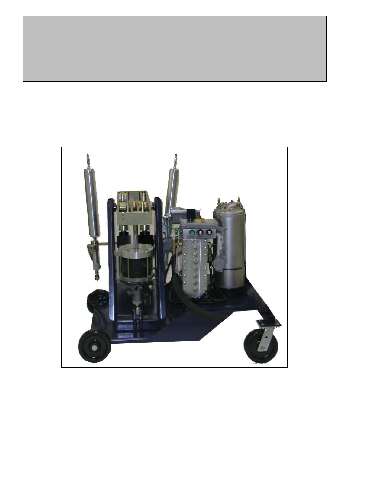
INTRODUCTION
The EPO3 Dual Pump Meter/ Mix Unit
INSTALL THE NEW UNIT
Uncrate Unit
Tool List
Install Material Containers
Remove Unit Metal Cover
Turn Front Panel Controls Off
Front Panel Controls
Unit Side Panels
Install Electrical Wire
Install Hoses
Attach Air Lines
PRIME THE UNIT
Special Conditions: Sensitive Materials
Check Hose Fittings
Fill Solvent Tank
Disassemble Gun-Head
Pressurize Solvent Tank
Flush Gun
Recheck Hoses Fittings
Set Pump To Maximum Stroke Length
Recirculate Material
SET MATERIAL RATIOS
Find Mixing Ratio
Choose Pump Size
Set Pump to Ratio
Test For Proper Settings
Replace Unit Metal Cover
PRESSURE ADJUSTMENT
Select Injectors
Assemble Gun-Head
Recirculate Material Again
Page 4

Recheck Pressure
Correct Pressure Drift
Change To Operating Mode
Test Spray Patterns
THE ACCUMULATORS
Remove Fluid and Air Pressure
Charge Accumulators with Charging Pump
Test For Proper Mix
RESIN INJECTION
Requirements
Testing RTM Mix
SHUTDOWN PROCEDURES
Short-Term Procedure
Long-Term Procedure
WEEKLY MAINTENANCE
Maintenance Procedures
APPENDIX A: OPTIONAL EQUIPMENT
Air Assist Nozzle
Chopper
Digital Resin Meter
Nitrogen Accumulator Charging System
APPENDIX B: SPRAY NOZZLE LIST
Page 5

DANGER:
Only Qualified Electricians Should Install Electrical System!
WARNING:
Air Pressure Should Not Exceed 120 psi!
WARNING:
Wear Eye Protection When Working With Solvent!
WARNING:
Do Not Disable Pressure Relief Valve on Solvent Tank!
WARNING:
If Pump Runs Rapidly Shut Off Main Pressure Immediately!
DANGER:
Nitrogen Bottles Should Be chained Securely!
WARNING:
Never Allow Pump Pressure to Exceed 1200 psi Or Heaters May Rupture!
DANGER:
Never Operate Unit Without Accumulator Safety Cover!
WARNING:
Never Remove Accumulator Safety Cover Before All Air And Fluid Pressure Has Been
Relieved!
WARNING:
Charging Pump Handle Can Extend Rapidly When Air Pressure Is Connected!
DANGER:
Never Leave Flammable Solvents Under Pressure Overnight!
DANGER:
Never Remove Accumulator Safety Cover When Pressure Is Present in the Variable-Stroke
Pump Accumulator!
DANGER:
Failure To Clean Pressure Relief Valve System Can Result in Rupture of Accumulators, Hoses,
Or Heaters
Page 6

INTRODUCTION
The EP03 Dual Pump Meter/ Mix Unit
The EPO3 unit is a medium –to high-volume metering and mixing system capable of metering two
components at rations from 1:1 through 8:1, depending upon pump selection and pump settings.
The unit is capable of supplying a smooth, continuous flow of fully-mixed, reactive thermosetting
materials. A static mixing element used at the gun produces full mixing of most medium viscosity
epoxies, polyesters, and other thermosetting resins. Viscosity is reduced by using in-line heating
units which can increase fluid temperatures by as much as 50 per recirculation cycle.
Metering ratios are adjusted by re-positioning the upper-pivot point of the hardener pump. This
makes possible extremely fine adjustment of ratio settings.
Continuous flow from the gun is supplied with the use of two pressure-charged air accumulators
located at each pump outlet. These accumulators operate in a fashion similar to hydraulic power
accumulators that dampen momentary pressure hesitations which can occur during pump
reversal.
Proper operation of the EP03 is achieved by a balancing of fluid pressures during the initial gun
use. Factors affecting this pressure balancing function are: viscosity of the material, size of the
injector orifice in the gun ( the size of the orifice regulates back pressures) , temperature settings
(which affects viscosity), and accumulator charge. Once control of these variables is achieved,
you will have fully mixed material at the initial triggering of the gun.
Whenever you stop operation of the EP03 for more than 10 minutes, you must place the machine
in the recirculation mode. This ensures that fully heated material is always present in the pumps
and in the hoses leading to the gun. The recirculation mode prevents and initial shot of cold
material which may occur as the material cools in the unit.
Maintaining proper pressure balance during the change from recirculation to operation mode is
very important in achieving proper mixing immediately upon triggering of the gun. We advise you
to concentrate on this aspect of operation during your initial training on the EPO3 unit.
The EPO3 unit can operate in several different configurations depending on accessories and
options. This unit can be used to spray certain materials, pour and cast, or perform RTM (Resin
Transfer Molding).
You can also attach a fiberglass chopper to the gun-head for addition of reinforcing fibers to the
material. Other options, such as digital timers, can be added as well. The EPO 3 can be used in
conjunctions with MVP’s high-production automated machinery such as Reciprocators,
Impregnators, and Winders. See your MVP catalog for complete descriptions of these systems.
Before you install the EPO3, you must consider the design of your material storage and handling
system. If you are working from five-gallon containers, you can easily use the pickup wands and
return hoses supplied with the system.
If you are working from 55-gallon barrels, you may consider installing these barrels in a horizontal
position with fittings attached to pickup material from the large bung hole and return material to the
small bung hole (with proper venting of the container.
Page 7

Larger quantities require installation of material containers with material heating supplied for
viscosity control. If your material is under 1,000 centipoise at room temperature, you can operate
without bulk material heating.
Page 8

CHAPTER 2
INSTALL THE UNIT
Uncrate Unit
Uncrate the unit and set on level floor surface at least 3 feet from the nearest wall to allow easy access.
Tool List
When preparing the EPO3 for use, it is important to have all of the tools, spare parts, and the supplies
available before beginning operation. The following tools (not shipped with the unit) must be available
when using the EPO3.
Protective gloves approved for use with all materials to be handled.
Eyeglasses approved by local safety and health agencies.
Respiration equipment approved by material supplier and safety and health agencies.
Cleaning solvents approved by material supplier and safety and health agencies.
Suitable solvent containers with safety lids approved as proper for flammable conditions.
Full set of open-ended wrenches (3/8”) through 1-½”)
Set of crescent wrenches (6”, 10”, and 12”).
Assortment of flat-ended screwdrivers from 1/8” through 3/8” blade size.
One medium-weight hammer.
Pliers.
Swivel socket wrenches (3/8”, and ½”)
6” table vice.
14” pipe wrench.
Strap wrench.
Machinist’s scribe form removing O-rings.
Balance-beam scale.
Four material containers (two types: 5 gallon material holding and 1 quart pre-weighed for ratio
calculation).
Install Material Containers
Install material containers next to the unit, preferably with some method of heating material. Recirculation
through unit heaters can also be used for preheating small quantities of materials.
Remove Unit metal Cover
Remove unit’s metal cover during setup procedures.
Turn Front Panel Controls Off
Make sure the unit is not connected to power and that all MAIN PANEL controls are turned off and the
regulators are turned to “0” (zero) (see Figure 1).
Page 9

(Figure 1. Front Panel Controls)
Turn off all front panel switches.
Turn all regulators to “0” (zero) or fully counterclockwise.
Turn off MAIN PRESSURE to unit. Check that heater indicator on the front panel is OFF (do not activate
heaters).
Front Panel Controls
Each control on the front panel is described in the following:
The HEAT indicator, on the left and right sides of the control panel, shows when the heaters are ON or
OFF. When the HEAT is on the lens turns green.
TEMP gauges indicate what the temperature is for the materials in the hoses.
MAIN PRESSURE switch turns on the pump that applies pressure to the materials.
MAIN PRESSURE gauge indicates how much pressure is being applied to the materials.
MAIN PRESSURE regulator allows you to vary the pressure applied to the materials.
FLUSH PRESSURE switchturns on the flushing system in the unit.
FLUSH PRESSURE gauge indicates pressure when the unit is being flushed.
FLUSH PRESSURE regulator varies the solvent system pressure.
RECIRCULATION PRESSURE switch allows the materials to be cycled through the unit without being
output from the gun-head. The gun trigger is in the middle position during recirculation mode.
RECIRCULATION PRESSURE gauge indicates what the pressure is when the unit is in recirculation
mode.
RECIRCULATION PRESSURE regulator varies the recirculation pressure.
PRE-HEAT button is pushed and held in for the period of time it takes for the heater block to warm up.
BLOCK HEAT switches allow you to select LOW, OFF, or HIGH temperature for the block heaters.
LINE HEAT switches allow you to select LOW, OFF, or HIGH temperature for the line heaters.
Unit Side Panels
The location of the connections and hoses for the INLET and OUTLET PANELS are shown in
Figures 2 and 3.
Inlet Panel
POWER SUPPLY connection
RESIN RETURN HOSE
RESIN SUPPLY
HARDENER PUMP RELIEF valve
(“PUMP H”).
HARDENER RETURN HOSE
HARDENER SUPPLY
AIR INLET
Page 10
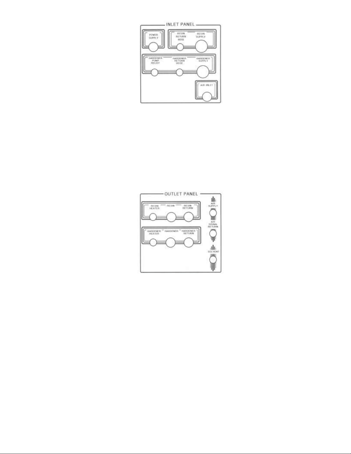
Outlet Panel
RESIN HEATER
RESIN
RESIN RETURN
HARDENER HEATER
HARDENER
HARDENER RETURN
AIR SUPPLY
AIR SIGNAL RETURN
SOLVENT
(Figure 2. Inlet Panel)
(Figure 3. Outlet Panel)
Install Electrical Wire
DANGER: Only Qualified Electricians Should Install Electrical System!
Install electrical wire (220 single phase, 25 amp) through manifold panel at lower side of machine (see
Figure 4). If flammable materials are to be processed, explosion –proof wiring must be used.
To install the unit hoses, perform the following steps:
Unpack all hoses and inspect for kinks or damage.
Install green pickup hoses and black recirculation hoses to INLET PANEL on left side of the right panel.
Install high-pressure relief hose to lower fitting at the same panel. Place hoses in correct material
containers.
Be extremely careful to match the proper recirculation hose with the correct pickup wand or material will be
contaminated. The high-pressure relief hose should be placed in a separate container.
Page 11
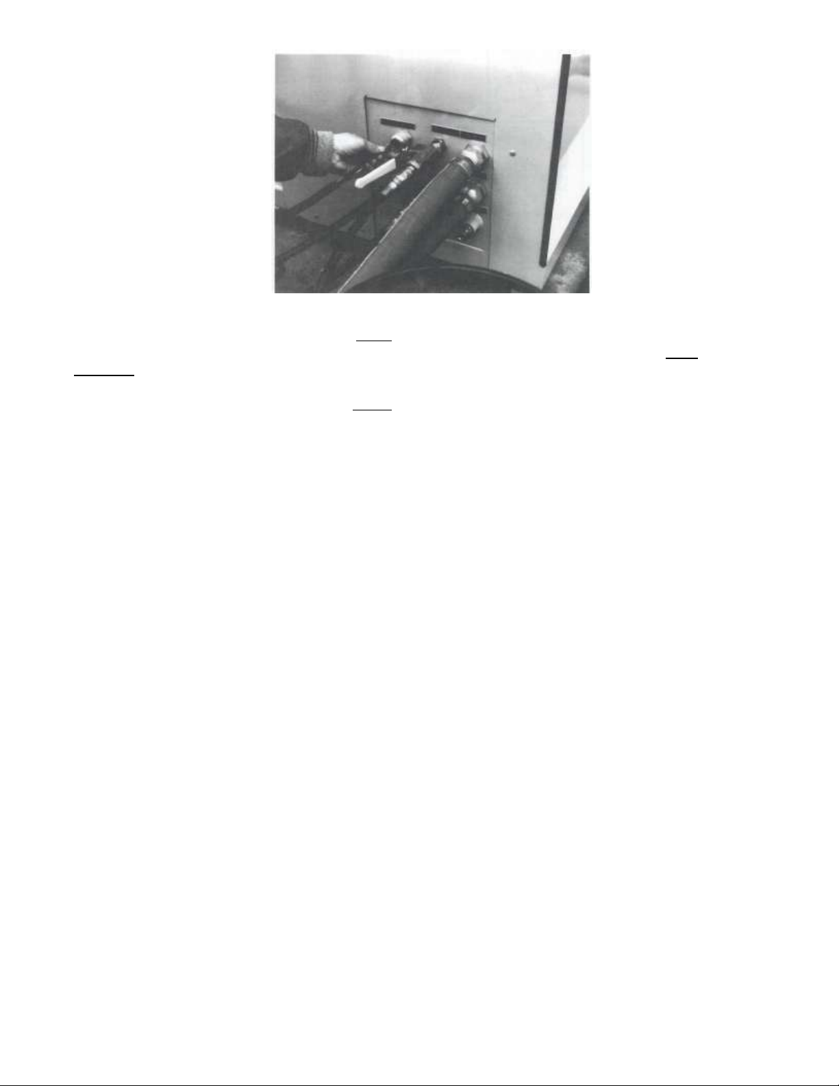
(Figure 4. Power Supply Connection)
Install gun hoses at OUTLET PANEL with black supply hoses and recirculation hoses attached at left side
of right panel according to fitting sizes (see Figure 3). Be extremely careful to attach the resin and
hardener recirculation hoses to the proper fitting or material cross-over can occur. Use colored tape to
color-code hoses according to material.
Place pickup wands into barrels or attach green hoses to bottom fitting on bulk containers. Place
recirculation hoses into proper containers, being careful not to mix hoses and move materials between
containers. Colored tape should be applied to the hoses to ensure material is not accidentally crossed
over.
Attach Air Lines
WARNING: Air Pressure Should Not Exceed 120 psi!
Install air line (at least ½” diameter) to unit and air compressor capable of at least 40 cfm. Attach air lines
to right side of INLET hose panel.
Page 12

CHAPTER 3
PRIME THE UNIT
Special Conditions: Sensitive Materials
If your materials are extremely sensitive to moisture or contamination, it is advisable to first prime both
pumps with a compatible solvent to remove any oil residue from the unit. The solvent containers should
then be disposed of properly.
Use approved containers for all flushing and priming procedures.
Check hose Fittings
Check all hose fittings on the unit to be sure they are tight.
Fill Solvent Tank
WARNING: Wear Eye Protection When Working With Solvent!
To fill the solvent tank, perform the following steps:
Release all air pressure from solvent tank by pulling the ring on the top of the pressure-relief valve and
turning ½ turn to lock open (see Figure 5). After all the air has exited through the valve, remove the solvent
tank hatch by pulling wire handle directly up and pressing hatch into solvent tank and turning hatch ½ turn
before removing (see Figure 6).
(Figure 5. Air Pressure Relief Valve) (Figure 6. Solvent Tank Hatch)
If solvent is splashed on the rubber O-ring, swelling can occur. Two O-rings have been supplied in case
this happens. However, the O-ring can be re-used. Set it aside and it will return to normal size overnight.
If necessary, the solvent tank can be removed from its bracket and hoses can be removed to allow easy
filling.
Pour solvent through opening in tank and fill to approximately 2/3 full with solvent. Do not over-fill or
solvent could be forced through back of the control panel. Replace solvent tank cover.
Close relief valve at top of tank by turning relief valve locking ring2/3 turn and allowing it to snap into place
(see Figure 7).
Page 13

Disassemble Gun-Head
Remove mixing tube or spray nozzle from gun-head (see Figure 8). Remove turbulent mixer (if used) and
front resin gun plug from gun to allow proper solvent flushing (see Figure 9).
Remove check balls and valve springs and clean with solvent.
Inspect the check ball seats for hardened material. If you find any, clean the seat with solvent.
Caution: Note which side of the gun the check ball and valve spring are taken so that when you
reassemble the gun-head they are not swapped causing materials contamination.
(Figure 7. Relief Valve Locking Ring) (Figure 9. Remove Front Resin Gun Plug)
Pressurize Solvent Tank
WARNING: Do not Disable Pressure Relief Valve on Solvent Tank!
Turn FLUSH PRESSURE switch on the front panel to the “ON” position and turn FLUSH PRESSURE
regulator until gauge reads approximately 40 psi. You should hear air entering the solvent tank.
Flush Gun
Press forward on the trigger of the gun to activate the flush valve and wait for steady stream of solvent to
exit the gun. The gun-head of the EPO3 must be flushed with solvent immediately after each use. It is
extremely important to flush the gun even during short time periods between usage.
Note: The solvents selected for gun flushing should be determined by the manufacturer of the chemical
system. Many chemical systems, such as isocyanates, are extremely moisture-sensitive and require
special solvents. Consult your materials suppliers data sheets for proper solvents or consult with your
materials supplier.
Recheck Hose Fittings
Recheck hose fittings or solvent leaks and tighten if necessary.
Set Pump to Maximum Stroke Length
WARNING: If Pump Runs rapidly Shut Off Main Pressure Immediately!)
Set variable-ratio pump to maximum stroke length by loosening four bolts on slave-arm adjusting bracket
(see Figure 10) and turning large hex nut at the end of adjusting screw until pump has reached maximum
stroke length (see Figure 11)
Page 14

(Figure 10. Loosen Slave Arm Bolts) (Figure 11. Adjust Slave Arm Screw)
Check that all ball valves levers located on INLET PANEL are in the open position (parallel with the hoses).
The location of the ball valves is described in the following list:
One on each pump (2).
One on the RESIN RETURN HOSE.
One on the HARDENER RETURN HOSE.
Recirculate Material
Material must be recirculated past the gun-head through a return fitting to prime the unit. No material will
exit the gun. To recirculate material, perform the following steps:
Turn on MAIN PRESSURE switch and leave pressure regulator set at “0” (zero). This brings air into the
recirculation control system.
Turn RECIRCULATION PRESSURE switch “ON” and slowly increase the regulator pressure until the pump
is cycling (priming) slowly.
Observe fluid pressure at resin and hardener pump pressure gauges attached to the pump as seen from
the back of the unit. Do not operate the unit if recirculation pressure is higher than 1200psi in either pump.
Adjust material viscosities by heating the container which shows the highest pressure on the pump gauge.
Use customer-supplied heating sources such as heat bands or water-jacket heating system on the material
containers. The EPO3 in-line heaters do not have enough wattage to efficiently heat large amounts of
material.
Apply heat until temperature of the material in the container is high enough to reduce viscosity to a point
where both pump pressures are balanced or nearly balanced. Do not heat material past 250º F.
While the unit is recirculating material, check for sudden movement of the pumps either on the upstroke or
downstroke. That would indicate gelled or hardened material is present on the ball seats requiring the
pumps to by disassembled and cleaned. Operation of pumps at high pressures with high viscosity
materials may also result in cavitation or diving movement on the pump which would need correcting.
Wait until material is seen exiting recirculation hoses back to material container in a steady stream before
turning RECIRCULATION PRESSURE switch to “OFF”.
Turn RECIRCULATION PRESSURE knob counterclockwise to the “0” position.
Note: If pumps do not prime, slowly increase RECIRCULATION PRESSURE until pump is running at
approximately one cycle per second. If pump does not immediately slow down when material reaches fluid
piston, stop this procedure and use the following procedure.
Disconnect the green supply hoses from the inside of the INPUT panel.
Pull hoses free from the unit and pour material into the open hose fittings with hose raised high enough for
material to flow to bottom of the pump and wet the inlet balls.
The unit should now prime easily.
Page 15

CHAPTER 4
PRIME THE UNIT (contd.)
Find Mixing Ratio
Consult your material data sheet to find proper mixing ratio. Set variable-stroke length pump to proper ratio
number as stamped on top edge of slave-arm (see Figure 12)
Choose Pump Size
To select the correct pump size, perform the following steps:
If the material requires greater than a 4:1 ratio, use a smaller diameter variable-stroke fluid pump (1 ¼”). In
this case, refer to the number stamped on the left side of the slave-arm (seen from back of unit)
If the material you are using requires 1:1 through 4:1 mixing ratios, you should normally be operating with
matched standard fluid pumps (1 ¼”). In this case, refer to the number stamped on the right side of the slavearm.
Set Pump To Ratio
Stop the pump at this time.
Set variable-stroke length pump to proper ratio number (stamped on top edge of slave arm). If the material
ratio falls between two numbers (such as 2.1:1), estimate fractional position between the two numbers. Lock
the pump in position by tightening all 4 bolts on the slave arm adjusting bracket.
(Figure 12. Set Pump To Proper Number Ratio)
Test For Proper Settings
Note: Read through this section completely before beginning the flowing procedure.
After setting and locking the pump position, you are ready to test the unit for proper ratio settings.
Check that all pressure has been removed from fluid pressure accumulators.
The accumulators are the tall, narrow cylinders attached to the side of each pump. To relieve
ACCUMULATOR PRESSURE, turn RECIRCULATION PRESSURE regulator to zero and switch recirculation
pressure switch to “ON”. All fluid should then drain from the accumulator hoses into material containers.
Turn on the RECIRCULATION switch to have the materials exit the hoses into the material containers. Wait
for a steady stream of material. Have a helper hold the two recirculating hoses over material containers while
someone quickly places two pre-weighed containers from the stream after the length of time you have chosen.
If you are checking ratios by volume it is not necessary to pre-weigh containers.
Page 16

Choose an arbitrary length of time, such as thirty seconds and remove both pre-weighed containers from the
stream after the length of time you have chosen. If you are checking ratios by volume it is not necessary to
pre-weigh containers.
If, after checking the ratios, you have an inaccurate ratio, loosen the slave-arm and adjust slightly before rechecking the ratios. Mark reference points on the slave arm with a pencil after each adjustment.
You may need to repeat material ratio test before you get the variable-stroke pump set correctly. If this is the
case, be sure to empty and weigh the test containers again before collecting fluid for testing the ratios.
When the correct setting for the slave-arm pump is found, mark the block at the front of the slave-arm bolt
block.
After you have set the pumps, you are ready to adjust the operating pressure to obtain the desired spray
pattern or the desired resin injection (RTM) flow rate, depending on your application.
Replace Unit Metal Cover
Unit metal cover should always be in place during operation of the unit to protect operator in case of high
pressure rupture.
Page 17

CHAPTER 5
PRESSURE AND ADJUSTMENT
Select Injectors
Four injectors are supplied with each unit and must be selected for each application according to back
pressures developed by the variable-ratio pump (#1 is the largest, #4 is the smallest).
Typically the #3 injector should be used for 3:1 ratio materials and #4 injector should be used for 4:1 ratio
materials, etc. High ratio materials require less flow through the injector.
The orifice of the injector must be sized to maintain proper back pressure to the pump (see figure 13).
Viscosity, temperature, surface tension, and other factors affect the back pressure developed by this injector.
Because of the se factors, injector selection must always be done by trial-and-error. If pressures at the pump
gauges cannot be balanced within 200psi by injector selection, modify viscosity of materials by heating.
Select injectors according to flow rate and viscosity of materials.
(Figure 13. Select Injector)
Assemble Gun-Head
Grease all threads with compatible grease (usually Lubriplate™).
Insert turbulent mixer in nozzle port (see Figure 14).
Assemble air-assist nozzle onto gun. Refer to MVP Nozzle charts (Appendix B) for nozzle
selections.
Insert injector into gun-head and screw in gun plug (see Figure 15).
Recirculate Material Again
WARNING: If Pump Runs Rapidly Shut Off Main Pressure Immediately!
To operate the unit in RECIRCULATION mode perform the following steps:
Turn MAIN PRESSURE switch “ON” and leave pressure regulator set at “0” (zero) to bring air
into the recirculation control system.
Turn RECIRCULATION regulator switch “ON” and slowly increase regulator pressure until pump
is cycling (priming) slowly. Wait until material is seen exiting recirculation hoses back to
material container in a steady stream before turning RECIRCULATION switch to “OFF.”
Note: Unit should be left in recirculation mode if not operating or material will cool off in hoses and pumps.
Page 18

(Figure 14. Assemble Turbulent Mixer) (Figure 15. Insert Injector)
Recheck Pressure
Set MAIN PRESSURE to estimated operating pressure of the unit.
Start at 30psi for RTM and 50 psi for spraying.
Pull gun trigger and operate until pressure stabilizes.
Check pressure gauges mounted on the front panel.
If one gauge reads more than 200psi higher pressure than the other, increase resin heater on
that side of the machine by turning block heat knob to an increased value position. Hold the
PRE-HEAT button for two minutes before operating the unit again.
If pressure difference is still too great, heat material containers until both pump gauges read
within 200 psi while recirculating. It may be necessary to re-adjust the block heat until the
temperature stabilizes.
It may be impossible with some materials to find the correct ratios to achieve balanced fluid pressures. When
you have installed the smallest or largest injector to adjust pressure and have heated the material on the highviscosity side to 150F (or highest temperature recommended by material supplier) you may have to
compensate for pressure differences with procedures described in section 5, “Correct Pressure Drift.”
Spray a test sheet while a helper watches both pump gauges to monitor pressure differences.
If the variable-stroke pump pressure drops more than 200 psi below the fixed pump’s pressure during the
initial pump stroke, adjust “PUMP H” (variable-ratio pump) recirculation pressure with recirculation ballvalve on INLET panel before switching to operating mode.
Note: If pressures differ over 200psi, see “Correct Pressure Drift.” If pressures do not differ by more than 200
psi, in Section 5, “Change to Operating Mode.”
Correct Pressure Drift
WARNING: Never allow Pump Pressure To Exceed 1200 psi Or Heaters May Rupture!
If operating pressures differ too much (over 200 psi) during initial pump stroke, use the following procedure:
Operate unit at recirculation pressure and slowly throttle down recirculation valve on the INLET panel
which controls flow from the variable-ratio pump known as “PUMP H.”
DANGER: Never Operate Unit Without Accumulator Safety Cover!
Watch pressure gauge on the variable-ratio pump. When this gauge reaches approximately 200 to 300
psi greater than “PUMP R,” turn RECIRCULATION PRESSURE switch to “OFF” position. This
procedure may be necessary to build full operating pressure in “PUMP H” accumulator. “PUMP H” has
a shorter stroke than “PUMP R” and therefore may need this pre-pressurizing procedure in order to
achieve full flow immediately upon activating the gun.
Page 19

It is also possible to help compensate for this effect by proper selection of accumulator sizes on the “PUMP H.”
A hardener pump operating at an 8:1 ratio may be equipped with an accumulator having approximately 1/8 the
volume of the resin accumulator (4:1 at ¼, etc.).
When using accumulators at this reduced volume, the charging and testing procedure must be performed
correctly. Properly matched accumulators may prevent the necessity of pre-pressurizing the “PUMP H” by
restricting recirculation.
Change to Operating Mode
Upon completion of the MAIN PRESSURE adjustment procedure, be sure that the 4 ball valves on the INLET
panel are set to the fully open position (see Section 3, Set Pump To Maximum Stroke Length).
Set the RECIRCULATION PRESSURE switch “OFF” and MAIN PRESSURE switch “ON.” Repeat this
procedure whenever the unit is placed in recirculation mode.
Note: The gun-head must be reassembled before pattern testing can be done.
Test Spray Patterns
Lay out a strip of paper for the spray test and perform the following test:
Note: You need two people for this test.
Turn on MAIN PRESSURE switch and adjust MAIN PRESSURE to 50 psi.
Turn RECIRCULATION PRESSURE “ON” and adjust the pressure until pump is operating at
approximately one stroke every two seconds.
When the gun trigger is pulled back, the air valve on the gun activates an air signal in the machine to switch
from recirculation air pressure to MAIN PRESSURE. The same air signal closes two ball valves on the INLET
PANEL and shuts off both recirculation lines. All fluid exits the gun nozzle rather than returning to the
containers.
The gun operator starts spraying onto the test strip and the second operator adjusts the MAIN PRESSURE
knob up or down as required for a proper spray pattern output (see Figure 16).
CAUTION: If you should stop spraying for any reason, immediately flush the gun-head using the
following procedure:
Place the gun-head into an approved container and push forward on the trigger until a steady stream
of solvent pours into the container).
(Figure 16. Initial Spray Pattern)
Page 20

If the pressure is not adequate to form a well-defined fan pattern, increase the MAIN PRESSURE until there is
just enough pressure to form a proper fan pattern.
Described in the following are possible problems and their solutions with fan pattern:
One Narrow Stream: The MAIN PRESSURE is too low for the material you are using (see Figure 16 on
previous page).
Solution: Increase the MAIN PRESSURE. Increase the material’s temperature. Use a smaller nozzle size.
Three Heavy Fingers Horns are beginning to develop but the MAIN PRESSURE is still too low (see Figure
17).
Solution: Increase MAIN PRESSURE. Increase material pressure. Use a smaller nozzle size.
Middle Stream Not Full Width Middle Stream is wider but not the full width it should be for the nozzle (see
Figure 18).
Note: See Appendix B for spray nozzle list.
(Figure 17. Narrow Middle Stream Pattern) (Figure 18. Wider Spray Pattern)
Solution: Increase MAIN PRESSURE. Increase material’s temperature.
Pattern Near Full Width There are well-defined fingers; however, there is little or no white frothing (air
bubbles) in the center of the sprayed material (see Figure 19)
Solution: Slightly increase the operating pressure. Slightly increase material’s temperature.
Result: PATTERN IS AT FULL WIDTH and the fingers are well-defined. White frothing appears in the
sprayed material. However, the white froth should disappear in less than 2 minutes (see Figure 20).
Note: This is considered the best general set of conditions for the fan pattern. Keep notes of the MAIN
PRESSURE and the material TEMPERATURE gauge readings when the pattern is correct.
Page 21

(Figure 19. Almost Normal Spray Pattern) (Figure 20. Normal Spray Pattern)
Pattern Too Wide: Heavy misting is seen and smelled, and there is significant overspray (material laid down
beyond the main pattern). The heavy frothing does not disappear within 2 minutes (see Figure 21)
Note: This is the most common problem in running the unit.
Solution F: Reduce the MAIN PRESSURE until the fan pattern fails, then increase the pressure until the
proper fan pattern returns.
Note: If frothing remains, the pressure is excessive and should be reduced. At this point, increase pressure to
the optional air assist nozzle from the front panel regulator labeled AIR ASSIST.
A properly adjusted air assist nozzle distributes material evenly across the spray fan without excessive fuming
or misting. If air assist adjustment does not produce a good pattern, increase the temperature at the in-line
heaters until the pattern improves. Upon completion of testing the spray pattern, pump accumulators should
be charged to their proper operating pressures.
(Figure 21. Spray Pattern Too Wide)
Page 22

CHAPTER 6
THE ACCUMULATORS
If Removal of the variable-stroke accumulator safety cover is necessary, place the rubber sleeve (1)
over the accumulator and then install the safety shield (2) (see Figure 22)
Remove Fluid and Air Pressure
WARNING: Never Remove Accumulator Safety Cover Before All Air And Fluid Pressure Has Been
Relieved!
Remove all fluid pressures from the unit by using the following procedure:
Turn “ON” the MAIN PRESSURE switch.
Turn “OFF” the MAIN PRESSURE regulator completely.
Turn “OFF” the RECIRCULATION PRESSURE regulator.
Turn “ON” the RECIRCULATION PRESSURE switch.
CAUTION: If any pressure is showing on the PUMP PRESSURE gauges, STOP this procedure
immediately and find the source of restriction before charging accumulators.
Remove charging valve caps. Shield eyes from valve and release all air charge from accumulators
by inserting a small allen wrench into charging valves located at top of the accumulators (see Figure
23).
(Figure 22. Variable-Stroke Accumulator Pump Safety cover) (Figure 23. Relieve Pressure)
Charge Accumulators with Charging Pump
WARNING: Charging Pump Handle Can Extend Rapidly When Air Pressure Is Connected!
After all air has escaped from the resin and hardener pump accumulators, you can re-charge
accumulators using the following procedure:
Turn “OFF” the heaters.
Fully extend pump handle from pump to avoid injury upon connecting air hose (see Figure 24).
Hand tighten hose fitting from charging pump onto accumulator charging valve at top of accumulator
(see Figure 25).
Page 23

Attach red line-air hose from manifold of unit (located on the pump pivot support bracket) to quickdisconnect.
(Figure 24. Extend Charging Pump Handle)
(Figure 25. Attach Charging Hose)
Be sure recirculation valves (located on the INLET PANEL) are open so fluid can exit accumulator
during charging.
The gauge on the charging pump should read line pressure.
Operate charging pump by placing handle against your chest and pressing pump against the handle.
Charge accumulator to approximately 100 psi less pressure than the fluid pressure reached when
setting up the proper spray pattern.
Wait until fluid is out of the recirculation hose before final stroke of the charging pump.
The gauge needle will bounce slightly during pumping and you should only refer to the pressure
reading reached at the peak of the bounce during the retraction stroke of the charging pump. (Air
escaping from the recirculation hose indicates gelled material at the accumulator ball seat).
Remove air quick-disconnect from charging pump and then remove hose fitting from accumulator
charging valve.
Stroke pump several times to remove fumes which could contaminate the other accumulator.
Repeat entire procedure on opposite accumulator at the same charging pressure. Replace
accumulator charging valve caps.
Test spray, or pour, again (see Section 5) and watch for pulsations. Check for air leaks.
Page 24

If pulsations occur, repeat entire accumulator charging procedure at ½ the previously tested charge
and then increase the charge at 100 psi increments until pulsation disappears. If adjustment of
charging pressures does not remove pulsations during the reversal of the pump, it may be necessary
to select a different accumulator size for the variable-stroke pump.
Test For Proper Mix
To test spray –up pattern, spry strip of material on a piece of paper with steady gun movement across
the paper. Observe material (after cue has taken place) for spottiness in the cure. This will indicate if
accumulators are properly charged.
If cure is spotty and flow from gun is steady, hardener pump accumulator may require different
charging pressure. If you have not charged the fluid accumulator to a pressure 100 psi less than the
operating pressure of the hardener pump, than recharge accordingly. If these pressures match and
curing is still spotty, try re-charging at 100psi more than fluid pressure.
If adjustment of hardener pump accumulator charge does not solve the problem, then adjust charging
pressure on resin pump accumulator with same procedure.
If this process is not successful, you may have gelled material in the inlet ball or piston ball of the fluid
pumps. This condition will usually show as a pump-diving movement or as a pulsation in the spray
pattern. You may also observe fluctuation of pressure gauges in one ore both pumps.
If any of these problems occur, disassemble and clean the fluid pump section.
Page 25

CHAPTER 7
RESIN INJECTION
Requirements
The RTM (Resin Transfer Molding) is identical to the spraying process with the exception of the lower
operating pressures. It may be possible to operate MAIN PRESSURE at the same pressure as recirculation
pressure, eliminating some procedures necessary for balancing startup pressures.
Resin injection also requires the use of a static-mixing tube attached to the standard gun-head to achieve
proper blending of tube components. Static mixing tubes are available in ¼”, 3/8”, ½” and ¾” sizes depending
upon flow rate requirements.
Caution: Mixing tubes are precision instruments and must be handled with extreme care.
Testing RTM Mix
To check proper mix for RTM, use the following procedure:
Lay a narrow strip of material across a piece of paper and check for pump pulsations during pouring
process.
Inspect material for full Barcol hardness or use other industry standard method to test for proper
hardness.
Any uncured area in this test strip indicates one or more of the following problems:
Accumulators are charged with either too little or too much pressure.
Accumulator volume is not properly matched to the pumping ratio or material viscosity.
Pump cavitation is occurring due to improper feeding of pump inlet or improper action of inlet ball.
Fluid restriction or blockage is occurring.
Pump pressures are fluctuating excessively during the switch from recirculation to the main operating
pressure.
Loose fittings on the inlet hoses (pump diving).
Caution: Flush the gun between resin injection operations to avoid ruining the static-mixing tubes.
Page 26

CHAPTER 8
SHUT DOWN PROCEDURES
Short-Term Procedure
DANGER: Never Leave Flammable Solvents Under Pressure Overnight!
When shutting down unit for more than 10 minutes but less than two weeks, use the following procedure:
Flush the gun-head with solvent by pushing the trigger forward.
Disassemble the gun-head and clean with the proper solvent (see Figure 26).
Flush the gun-head again with solvent.
Remove air pressure at MAIN PRESSURE gauge.
Turn OFF power to the unit.
Remove pressure from the flush tank by pulling and locking flush tank pressure-relief valve.
Moisture-reactive materials must be covered with dry nitrogen, if possible.
Reassemble the gun-head when you use the unit again.
Long-Term Procedure
When shutting down unit for more than two weeks, use the following procedure:
Thoroughly flush unit by pumping solvent through gun, then flush solvent through recirculation system.
(Figure 26. Clean Gun Parts)
Relieve all air and fluid pressure in the unit and in the accumulators.
Disassemble both pump filters and accumulators. Thoroughly clean filter screens with approved
solvent. Reassemble pump filters and place lubricant on threads (see Figure 27).
Disassemble the pressure-relief valve and thoroughly clean it (see Figure 28).
Empty pump-shaft lubrication cups by removing small plastic plugs. Wipe cup section clean with a rag
and solvent (see figure 29).
Disassemble the pumps and clean them thoroughly.
Reassemble the pumps.
Page 27

(Figure 27. Clean Filters) (Figure 28. High Pressure Relief Valve)
(Figure 29. Fill Pump Shaft Oil Cups)
Page 28

CHAPTER 9
WEEKLY MAINTENANCE
Maintenance Procedures
DANGER: Never Remove Accumulator Safety cover When Pressure Is Present in The Variable-Stroke Pump
Accumulator!
Preferably Friday evening or the last workday of the week, perform the following maintenance steps:
Clean the high pressure relief valve system and accumulators.
Clean fluid filter with proper solvent.
Bleed all water traps, compressor system and water trap located on air manifold (on pump pivot support
bracket) (see Figure 30).
Check and fill the following lubrication systems:
Check air motor pump oiler attached to power head, (see Figure 31) and fill lubrication systems if
needed.
(Figure 30. Bleed Water Traps) (Figure 31. Fill Pump Oiler)
DANGER: Failure To Clean Pressure Relief Valve System Can Result In Rupture Of Accumulators, Hoses, Or
Heaters!
Clean both pump accumulators on a weekly basis, as well as the high-pressure release valve (located between
the variable-ratio pump and its filter) using the following procedure:
Disassemble both accumulators, the filter, and the high pressure relief valve (see Figures 32, 33, 34).
Remove charging valve caps from accumulators. Shield eyes from valve and release all air and fluid
pressure charge from accumulators. (Refer to “REMOVE PRESSURE,” and “REMOVE AIR
PRESSURE.”).
FLUID “PUMP R” AND “pump h”: shaft lubrication cups must be filled to 1” depth (see Figure 35).
Check pump shaft for signs of gelled material which indicates a need to replace pump shaft packings.
Page 29

(Figure 32. Disassemble Accumulators) (Figure 33. High Pressure Relief Valve).
(Figure 34. Clean Filters) (Figure 35. Fill Pump Shaft Oil Cups)
Thoroughly wash all components with the proper solvent. Flush solvent through the high-pressure
relief valve hose by using the special gun adaptor fitting supplied with the unit. (See Figure 36)
During this procedure, the pump filters should also be thoroughly cleaned. Liberally apply appropriate
lubricant to all threads to prevent thread damage when filters are reinstalled.
Thoroughly clean pickup wand pipes with solvent and cover pickup wand screens with plastic film to
prevent moisture contamination.
(Figure 36. Purge High Pressure Relief Hose)
Page 30

APPENDIX A
OPTIONAL EQUIPMENT
Air-Assist Nozzle
The optional Air-Assist Nozzle can be provided with a pressure gauge and regulator on the front panel o the
unit. This nozzle includes a small mixing element which can be supplemented by inserting a standard
turbulent mixer into the front of the gun-head. An air line goes to the air-assist nozzle.
The nozzles available for the air-assist are different from the standard MVP H.I.S. nozzles (see Appendix B for
list).
If frothing is seen during application, the pressure is too strong and should be reduced. Increase pressure to
the air-assist nozzle from the front panel regulator labeled AIR ASSIST.
A properly adjusted air-assist nozzle distributes material evenly across the spray fan without excessive fuming
or misting. If air-assist adjustment does not produce a good pattern, increase the temperature at the in-line
heaters until the pattern improves.
Chopper
An optional Chopper for chopping fiberglass roving can be supplied with your EPO3 spray gun. The Chopper
is easily mounted to the top of the gun handle and is adjusted with two eccentric washers which can be turned
to vary the spray angle of the Chopper. The Chopper can also be adjusted up and down vertically to match the
fiberglass spray patter with the resin spray pattern. An ideally adjusted Chopper has glass distributed evenly
across the resin fan without excessive fly-away strands. Several spray tests on a paper target are necessary
to properly set the Chopper.
Digital Resin Meter
This meter uses an optical sensor mounted on the fluid pump shaft which generates a “count” number. This
number can be easily translated to fluid flow by volume or weight.
The Digital Resin Meter can also be supplied optionally with an internal electric/pneumatic interface valve.
This valve can be used to automatically shut off the automatic H.I.S. gun-head. The gun-head can be
equipped with a pneumatic ON/OFF switch allowing you to press the ON switch and wait for the digital counter
to shut off the gun when the preset optical sensor count has been reached.
Nitrogen Accumulator Charging System
DANGER: Nitrogen Bottles Should Be Chained Securely!
When high operating pressures must be reached, it may be preferable to use the optional Nitrogen
Accumulator Charging System. This is a single stage regulator which can be attached to a standard dry
nitrogen bottle (see Figure 37).
To use the Nitrogen Accumulator Charging System, use the following procedure:
Be sure the following controls are properly set:
1. MAIN PRESSURE regulator “OFF.”
2. MAIN PRESSURE toggle switch “ON.”
3. RECIRCULATION regulator “OFF.”
4. RECIRCULATION toggle switch “ON.”
5. Fluid pressure gauge (hardener pump) reads “0.”
Page 31

(Figure 37. Nitrogen Charging System)
Remove the valve body cap on the top of both accumulators.
Note: Do not switch valve body caps between accumulators. The hardener pump’s cap must be returned to
hardener pump to avoid contamination.
Clean the end of an allen wrench or flat-end rod and insert in the top of the accumulator valve,
press down until all air escapes.
Attach nitrogen lines to the tops of the accumulators. Always use the same hose on the same
accumulator to avoid contamination.
Hand tighten the nitrogen hoses to the accumulators. Make sure the nitrogen tank’s regulator is
closed (turn counterclockwise).
Slowly open the main valve of the nitrogen tank one or two turns (see Figure 34 on previous
page).
Slowly turn the T-handle clockw9ise until the regulator gauge pressure equals the lower of the
two fluid pressures you found while spraying.
Slowly turn the regulator’s T-handle counterclockwise until it is turned off.
Disconnect the nitrogen hoses from the accumulators.
Check to see if the valve bodies are leaking by listening for hissing sounds.
Replace the valve body cap- finger tighten only.
Listen at the recirculation hose for hissing.
If you hear the charge escaping through the gun-head, the polyball in one or both of the accumulators is
probably not seating and must be cleaned or replaced.
If air still escapes the accumulator, replace the quad ring seal in the charging valve.
Many operators find this system preferable to hand charging. However, nitrogen bottles must be kept in
inventory. The key advantage to nitrogen charging is the assurance that there is not moisture in the charge.
Compressed air often has moisture contamination even with the highest quality refrigeration air frying systems.
Page 32

APPENDIX B
SPRAY NOZZLE LIST
Air-Assisted Spray Nozzle List
Use these lists to choose the best output, pattern width, and back pressure for your application.
Orifice Size Fan Angle Part Number Air Cap Used
(degrees)
0.023 40 30423 08228
0.027 40 30427 08229
0.031 40 30431 08229
0.035 40 30435 08229
0.043 40 30443 08229
0.023 50 30523 08228
0.035 50 30535 08229
0.043 50 30543 08229
0.023 60 30623 08228
0.027 60 30627 08229
0.031 60 30631 08229
Tungsten Carbide Spray Nozzle List
Orifice Size Fan Angle Part Number G.P.M.
(degrees) 500. P.S.I.
Water
0.026 25 2501 C 0.35
0.036 25 2502 C 0.71
0.043 25 2503 C 1.10
0.052 25 2503 C 1.40
0.062 25 2506 C 2.10
0.011 40 400017 C 0.06
0.013 40 400025 C 0.09
0.015 40 400033 C 0.12
0.018 40 400050 C 0.18
0.021 40 400067 C 0.24
0.023 40 400080 C 0.28
0.026 40 4001 C 0.35
0.031 40 40015C 0.53
0.036 40 4002 C 0.71
0.043 40 4003 C 1.10
0.052 40 4004 C 1.40
0.062 40 4006 C 2.01
0.072 40 4008 C 2.80
0.078 40 4010 C 3.50
0.011 50 500017 C 0.06
0.013 50 500025 C 0.09
0.015 50 500033 C 0.12
0.018 50 500050 C 0.18
0.021 50 500067 C 0.24
0.023 50 500080 C 0.28
0.026 50 5001 C 0.35
0.031 50 50015 C 0.53
0.036 50 5002 C 0.71
0.043 50 5003 C 1.10
0.052 50 5004 C 1.40
0.062 50 5006 C 2.10
0.072 50 5008 C 2.80
Page 33

0.011 65 650017 C 0.06
0.013 65 650025 C 0.09
0.015 65 650033 C 0.12
0.018 65 650050 C 0.18
0.021 65 650067 C 0.24
0.023 65 650080 C 0.28
0.026 65 6501 C 0.35
0.031 65 65015 C 0.53
0.036 65 6502 C 0.71
0.043 65 6503 C 1.40
0.062 65 6506 C 2.10
0.072 65 6508 C 2.80
Note: There are other fan angles available, but this list comprises our normal stock.
Page 34

Corporate Headquarters/Manufacturing
5148 113th Ave.
Clearwater, FL 33760 USA
Ph: (727) 573-2955
Fax: (727) 571-3636
Manufacturing/Sales
1862 Ives Ave.
Kent, WA 98032 USA
Ph: (253) 854-2660
Fax: (253) 854-1666
E-mail: info@mvpind.com · Web: www.mvpind.com
 Loading...