

Page 1
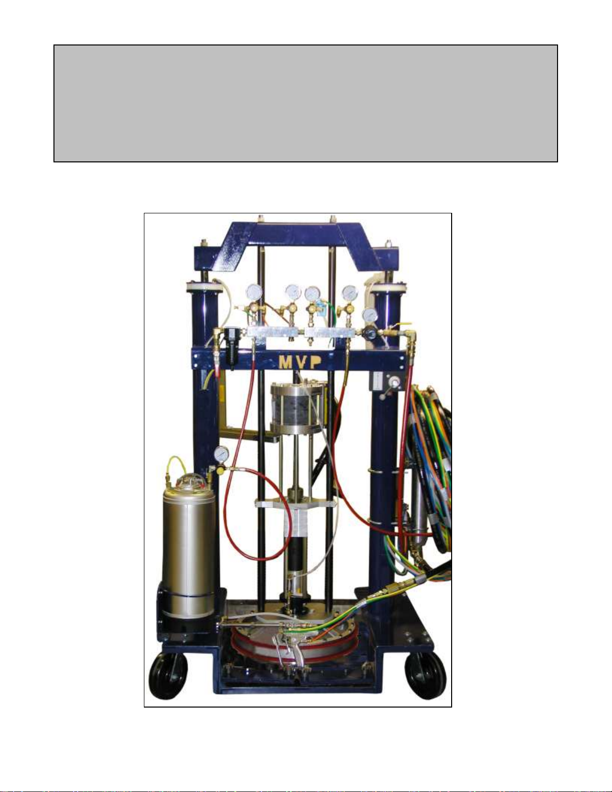
STAINLESS STEEL CHOP CHECK
PUMP FLUID SECTION MANUAL
REPAIR AND MAINTENANCE – CCPLS-1000-SS
MAGNUM VENUS PLASTECH
Stainless Steel Chop Check Pump – Repair and Maintenance CCPLS-1000-SS
03/29/2007
Page 2

TABLE OF CONTENTS:
STAINLESS STEEL CHOP CHECK PUMP FLUID SECTION MANUAL –
REPAIR AND MAINTENANCE:
CHAPTER 1 – SS FLUID SECTION DISASSEMBLY
CHAPTER 2 – SS FLUID SECTION ASSEMBLY
CHAPTER 3 – DRAWINGS
Page 3
CHAPTER
STAINLESS STEEL CHOP CHECK PUMP FLUID SECTION
DISASSEMBLY
WARNING: When removing Pump Fluid Section, Hoses and Resin
Surge Chamber, be sure to bleed off fluid pressure from the system
before disconnecting. Release Surge Chamber charge before
removing Surge Chamber. System may be under pressure and cause
injury.
TO REMOVE THE FLUID SECTION FROM THE PUMP ASSEMBLY:
1. Put the pump into the lowest position of the down stroke.
2. Disconnect the resin hose from the side of the Pump fluid section.
Warning: Be sure to remove fluid pressure from the system before disconnecting
3. Remove the E-Ring (APP-9102), lift up the Sleeve (APP-9109) and remove the two
4. Remove the four Hex Head Bolts (02705-14) holding the fluid section to the Pump
5. Remove the four Hex Head Bolts (F-HB-06C-16) holding the fluid section to the
6. Remove the two Hex Nuts (7201-1-12) from the Support Rod (APD-1003)
7. Shift the Ram Control valve into the Ram up position, move the ram up until the pump
Note: As you disassemble, lay the parts out on a towel or rag in the order you take
FLUID SECTION DISASSEMBLY PROCEDURE:
Note: The Fluid Section can be rebuilt in place or easily removed and taken to a
workbench. Flushing the fluid section with suitable cleaning agent can make
the rebuild process much easier.
resin hose, tie rods or surge chamber. System may be under pressure and can
cause injury.
Connectors (APP-9096).
Mount Plate (CCP-1008).
Support Plate (CCP-1009).
mount plate will allow the pump fluid section to be removed.
them apart. This will help you remember how they go back together. Inspect
each part for wear or damage and note parts that require replacement.
Page 4
1. If not already done, move the pump to the bottom of the down stroke.
2. Remove Hex Cap Screw (F-HB-06F-12) from the bottom of the Priming Rod (CCPLS1027-SS). If the Priming Rod (CCPLS-1027-SS) spins put a wrench on the wrench
flats of the Priming Rod just above the Priming Piston (CCPLS-1023-SS).
3. Remove the Backup Washers (CCPLS-1028-SS), Relief Washer (CCPLS-1025) and
the Priming Piston (CCPLS-1023-SS) from the Priming Rod (CCPLS-1027-SS).
4. Unscrew the four Hex Nuts (7201-1-10) from the end of the Tie Rods (CCPLS-1020).
5. Pull the Priming Valve Housing (CCPLS-1026-SS) off the Tie Rods CCPLS-1020) and
out of the Foot Valve Housing (CCPLS-1019-SS).
6. Remove Lower Valve Seat (CCPLS-1018-SS) from out of the end of the Foot Valve
Housing (CCPLS-1019-SS).
7. Slide the Foot Valve Housing (CCPLS-1019-SS) off the Cylinder (CCPLS-1008-SS).
8. Unscrew the Tie Rods out of the Outlet Body (CCPLS-1007-SS).
9. Pull the Intake Valve (CCPLS-1031-SS) assembly off the Priming Rod (CCPLS-1027SS).
10. Unscrew the Intake Valve Packing Nut (CCPLS-1016-SS) from the Intake Valve
(CCPLS-1017-SS)
11. Remove the Lower Intake Valve Seal (CCPLS-1015) from inside the Intake Valve
(CCPLS-1017-SS).
12. Slide the Valve Stop (CCPLS-1014-SS) off the Priming Rod (CCPLS-1027-SS).
13. Pull the Cylinder (CCPLS-1008-SS) out of the Outlet Body (CCPLS-1007-SS) and off
the Piston Cups (CCPLS-1009).
14. Remove the Packing Nut (CCPLS-1006) from the top of the Outlet Body (CCPLS1007-SS).
15. Pull the Displacement Rod (CCPLS-1013-SS) from the V Packing (CCPLS-1002) and
Outlet Body (CCPLS-1007-SS), and set aside for now.
16. Remove the Rod Bushing (CCPLS-1001) from the top of the Outlet Body (CCPLS1007-SS).
17. Remove the Spring Support Ring (CCPLS-1005) and Wave Springs (CCPLS-1029)
from inside of the Outlet Body (CCPLS-1007-SS).
18. Remove the Female Compression Ring (CCPLS-1003-SS), Male Compression Ring
(CCPLS-1004-SS) and V Packing (CCPLS-1002) from inside of the Outlet Body
(CCPLS-1007-SS).
Note: If the parts are hard to remove from the top of the Outlet Body use a wood or
plastic dowel to push the parts out from the bottom. Cleaning with a solvent will
help loosen stuck parts.
Displacement Rod Disassembly –
Note: Clean and inspect all parts for wear and damage. Replace damaged parts and
all parts provided in the repair and seal kits.
1. Unscrew the Lower Piston Body (CCPLS-1012-SS) from the Upper Piston Body
(CCPLS-1011-SS). Use caution, the piston ball may fall out and become damaged. If
the ball falls onto a hard surface it may become scratched or get a flat spot on it.
2. Remove the Piston Ball (9201-2-36) and Ball Check Spring (3102-16-1) from the
Upper Piston Body (CCPLS-1011-SS).
3. Remove the Piston Cups (CCPLS-1009), Piston Cup Spacer (CCPLS-1010-SS) and
Piston Cup Backup Ring (CCPLS-1021-SS) from the Lower Piston Body (CCPLS1012-SS).
Page 5

CHAPTER
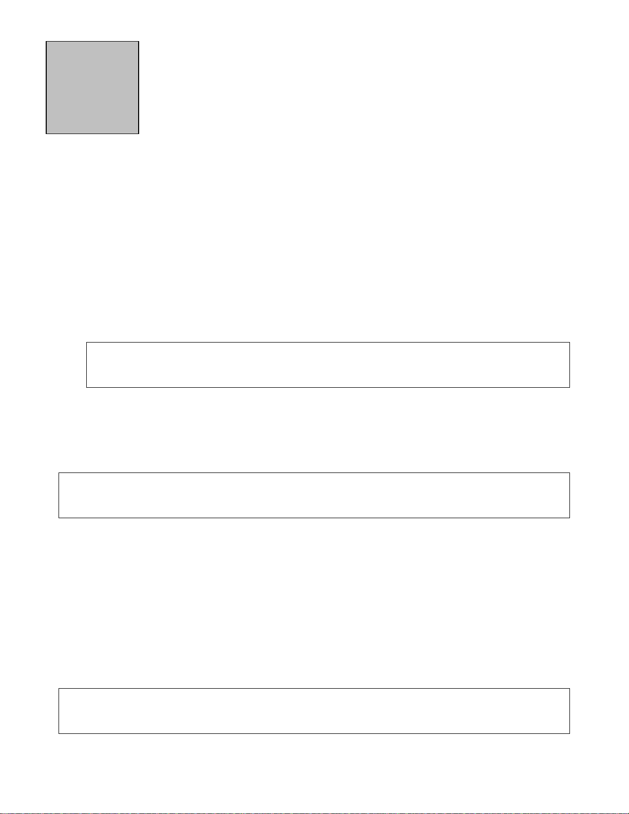
PISTON BALL SEAT – CCPLS-1022-SS
LOWER PISTON BODY – CCPLS-1012-SS
CHOP CHECK PUMP FLUID SECTION ASSEMBLY
FLUID SECTION ASSEMBLY PROCEDURE:
Displacement Rod Assembly -
1. Mount the Displacement Rod (CCPLS-1013-SS) in a vise by the wrench flats.
2. Apply a small amount of Loctite to the threads of the Upper Piston Body (CCPLS1011-SS) and thread it into the Displacement Rod (CCPLS-1013-SS).
3. Insert Ball Check Spring (3102-16-1) into the Upper Piston Body (CCPLS-1011),
larger end first.
4. Apply a light coat of red grease (6706-2-1) to Piston Ball (9201-2-36) and place it into
the Upper Piston Body (CCPLS-1011-SS), on top of the Ball Check Spring (3102-16-
1).
5. Press Piston Ball Seat (CCPLS-1022-SS) into Lower Piston Body (CCPLS-1012-SS),
with chamfer towards the ball. See below
Note: Use caution not to damage the ball seat area.
6. Slide Piston Cup Backup Ring (CCPLS-1021-SS) over the lower Piston Body
(CCPLS-1012-SS) ridged side up.
7. Apply red grease (6706-2-1) into the Piston Cups (CCPLS-1009). Slide one Piston
Cup (CCPLS-1009) with the cup side up over the lower Piston Body (CCPLS-1012SS) onto the Piston Cup Backup Ring (CCPLS-1021-SS).
8. Slide the Piston Cup Spacer (CCPLS-1010-SS) onto the Lower Piston Body (CCPLS1012-SS) so that the narrow end is inside the Piston Cup.
9. Place the other Piston Cup (CCPLS-1009) with the cup side up, over the Lower Piston
Body (CCPLS-1012-SS) down onto the Piston Cup Spacer (CCPLS-1010-SS).
10. Now thread the Lower Piston Body (CCPLS-1012-SS) into the Upper Piston Body
(CCPLS-1011-SS).
Note: Use caution not to over tighten the lower Piston Rod as it will damage the lip of
the piston cups.
Page 6

11. Apply a small amount of Loctite to the threads of the Priming Rod (CCPLS-1027-SS).
Thread Priming Rod (CCPLS-1027-SS) into the Lower Piston Body (CCPLS-1012SS).
Remove the Piston Rod from the vise and set aside.
Outlet Body Assembly –
1. Pack red grease (6706-2-1) into all of the V packing (CCPLS-1002) and Female
Compression Ring (CCPLS-1003-SS).
2. Apply a light film of red grease (6706-2-1) to the inside of the packing area of the
Outlet Body (CPLS-1007-SS).
3. Put together all four V Packing (CCPLS-1002) with the Male Compression Ring
(CCPLS-1004-SS) on one end and the Female Compression Ring (CCPLS-1003-SS)
on the other.
4. Put this V Packing Assembly into the Outlet Body (CCPLS-1007-SS) with the Male
Compression Ring (CCPLS-1004-SS) going in first.
5. Apply a light film of red grease (6706-2-1) to the ten Wave Springs (CCPLS-1029) and
insert them into the Outlet Body (CCPLS-1007-SS) onto the V Packing set.
6. Put Spring Support Ring (CCPLS-1005) into the Outlet Body (CCPLS-1007-SS) on top
of the Wave Spring set.
7. Insert Rod Bushing (CCPLS-1001) into the Outlet Body (CCPLS-1007-SS) onto the
Spring Support Ring.
8. Apply a little red grease (6706-2-1) to the threads of Packing Nut (CCPLS-1006) and
thread it into the Outlet Body (CCPLS-1007-SS), just enough to contact the Rod
Bushing (CCPLS-1001), do not tighten at this point.
9. Apply a light film of red grease (6706-2-1) to the Displacement Rod (CCPLS-1013-SS)
and to the Priming Rod (CCPLS-1027-SS).
10. Apply a light film of red grease (6706-2-1) to the Outlet Body (CCPLS-1007-SS) where
the Cylinder o-ring will be installed.
Note: It would be helpful to put the Outlet Body into a vise at this point, if the fluid
section has been removed from the pump mount bracket.
11. Gently insert the Displacement Rod (CCPLS-1013-SS) assembly into the Outlet Body
(CCPLS-1007-SS) and thru the V Packing (CCPLS-1002) from the outlet side.
12. Lightly grease both O-Rings (O-V-144) and install onto the Cylinder (CCPLS-1008SS).
13. Firmly press the Cylinder (CCPLS-1008-SS) over the Priming Rod and onto the Piston
Cups (CCPLS-1009), then into the Outlet Body (CCPLS-1007-SS).
14. Install the Valve Stop (CCPLS-1014-SS) onto the Priming Rod (CCPLS-1027-SS) up
to the bottom of the Cylinder (CCPLS-1008-SS).
Intake Valve Assembly –
1. Apply a light film of red grease (6706-2-1) to the inside of the Intake Valve (CCPLS1017-SS).
2. Lightly grease and install Lower Intake Valve Seal (CCPLS-1015) into the Intake Valve
(CCPLS-1017-SS).
3. Apply a drop of Loctite to the threads of the Intake Valve Packing Nut (CCPLS-1016SS) and thread it just a little ways into the Intake Valve (CCPLS-1017-SS).
4. Take the Intake Valve (CCPLS-1017-SS) assembly and install it onto the Priming Rod
(CCPLS-1027-SS), with the Intake Valve Packing Nut going on first.
Page 7

5. Finish tightening the Intake Valve Packing Nut (CCPLS-1016-SS) into the Intake Valve
(CCPLS-1031). Slide it up against the Valve Stop (CCPLS-1014).
Final Assembly –
1. Apply a light film of red grease (6706-2-1) to the inside of both ends of Foot Valve
Housing (CCPLS-1019-SS).
2. Slide the correct end of Foot Valve Housing (CCPLS-1019-SS) over the Priming Rod
and Intake Valve and onto the Cylinder (CCPLS-1008-SS).
3. Apply a light film of red grease (6706-2-1) to O-Ring (0-V-145) and install onto Lower
Valve Seat (CCPLS-1018-SS).
4. Install Lower Valve Seat (CCPLS-1018-SS) over the Priming Rod and into the Foot
Valve Housing (CCPLS-1019-SS).
5. Install the four Tie Rods (CCPLS-1020) into the Outlet Body (CCPLS-1007-SS) and
tighten.
6. Apply red grease (6706-2-1) to O-Ring (0-V-150) and install onto Priming Valve
Housing (CCPLS-1026-SS).
7. Install the Priming Valve Housing (CCPLS-1026-SS) and O-Ring (0-V-150) over the
Priming Rod and into the Foot Valve Housing (CCPLS-1019-SS) and onto the Tie
Rods (CCPLS-1020). Align the notch in the Priming Valve Housing opposite the outlet
hole in the Outlet Body.
8. Thread the four Hex Nuts (7201-12-8) onto the Tie Rods (CCPLS-1020) and tighten
them firmly against the Priming Valve Housing (CCPLS-1026-SS).
9. Apply a thin film of red grease (6706-2-1) to Piston Seal (CCPLS-1024) and install
onto Priming Piston (CCPLS-1023-SS).
10. Adjust the Displacement Rod (CCPLS-1013-SS) in the pump so just the wrench flats
are exposed out of the Packing Nut (CCPLS-1006).
11. Place the Priming Piston (CCPLS-1023-SS) onto the Priming Rod (CCPLS-1027-SS).
12. Place onto Hex Cap Screw (F-HB-06F-12) one Backup Washer (CCPLS-1028-SS) the
Relief Washer (CCPLS-1025) and the last Backup Washer (CCPLS-1028-SS).
13. Apply a drop of Loctite to the threads of Hex Cap Screw (F-HB-06F-12) and thread it
into the end of the Priming Rod (CCPLS-1027-SS). Tighten only till the Priming Rod
(CCPLS-1027-SS) starts to spin. Use caution not to over tighten, the Relief Washer
may become damaged.
Page 8

CHAPTER
3
CHOP CHECK PUMP DRAWINGS:
CHOP CHECK PUMP FLUID SECTION SS CCPLS-1000-SS
CHOP CHECK PUMP REPAIR KIT CCPLS-1000-RK
Page 9

33
CHOP CHECK PUMP FLUID SECTION SS
MAGNUM VENUS PRODUCTS
REV. -
CCPLS-1000-SS
(10)
SEE NOTE 1
NOTE:
1. INSTALL WITH RIDGES UP
3
2
4
6
13
1
5
7
13
11
30
29
9
9
10
21
22
12
27
8
34
34
14
16
15
17
19
18
36
26
27
24
23
26
37
20
20
20
20
28
28
25
32
31
31
31
TOP VIE OF
BOTTOM FLANGE
OUTLET
35
Page 10

CCPLS-1026-SS
26
PRIMING VALVE HOUSING
1
CCPLS-1025
25
RELIEF WASHER
1
CCPLS-1024
24
PISTON SEAL
1
CCPLS-1023-SS
23
PRIMING PISTON
1
CCPLS-1022-SS
22
PISTON BALL SEAT
1
CCPLS-1021-SS
21
PISTON CUP BACKUP RING1
CCPLS-1020
20
TIE ROD
4
CCPLS-1019-SS
19
FOOT VALVE HOUSING
1
CCPLS-1018-SS
18
LOWER VALVE SEAT
1
CCPLS-1017-SS
17
INTAKE VALVE
1
CCPLS-1016-SS
16
INTAKE VALVE PACKING NUT
1
CCPLS-1015
15
LWR INTAKE VALVE SEAL
1
CCPLS-1014-SS
14
VALVE STOP
1
CCPLS-1013-SS
13
DISPLACEMENT ROD
1
CCPLS-1012-SS
12
LOWER PISTON BODY
1
CCPLS-1011-SS
11
UPPER PISTON BODY
1
CCPLS-1010-SS
10
PISTON CUP SPACER
1
CCPLS-1009
9
PISTON CUP
2
CCPLS-1008-SS
8
CYLINDER
1
CCLPS-1007-SS
7
OUTLET BODY
1
CCPLS-1006
6
PACKING NUT
1
CCPLS-1005
5
SPRING SUPPORT RING
1
CCPLS-1004-SS
4
MALE COMPRESSION RING
1
CCPLS-1003-SS
3
FEMALE COMPRESSION RING
1
CCPLS-1002
2
V PACKING
4
CCPLS-1001
1
ROD BUSHING - DISPLACEMENT ROD
1
DESCRIPTION
PART NO.
ITEM
PARTS LIST
QTY
CHOP CHECK PUMP FLUID SECTION CCPLS-1000-SS
27
CCPLS-1027-SS
1
PRIMING ROD
CCPLS-1028-SS
28
2
BACKUP WASHER
9201-2-36
29
1-1/4" DIA BALL
1
3102-16-1
30
BALL CHECK SPRING
1
7201-1-10
31
HEX NUT
4
F-HB-06F-12
32
1
HEX CAP SCREW
O-E-150
34
37
36
35
33
2
O-RING
O-E-144
O-RING
O-RING
O-RING
O-E-018
O-E-145
1
1
1
WAVE SPRING
CCPLS-1029
10
Page 11

Page 12

Corporate HQ/Mfg. Manufacturing/Sales
5148 113th Ave. 1862 Ives Ave.
Clearwater, FL 33760 USA Kent, WA 98032 USA
Ph: (727) 573-2955 Ph: (253) 854-2660
Fax: (727) 571-3636 Fax: (253) 854-1666
E-mail: info@mvpind.com Web: www.mvpind.com
 Loading...